

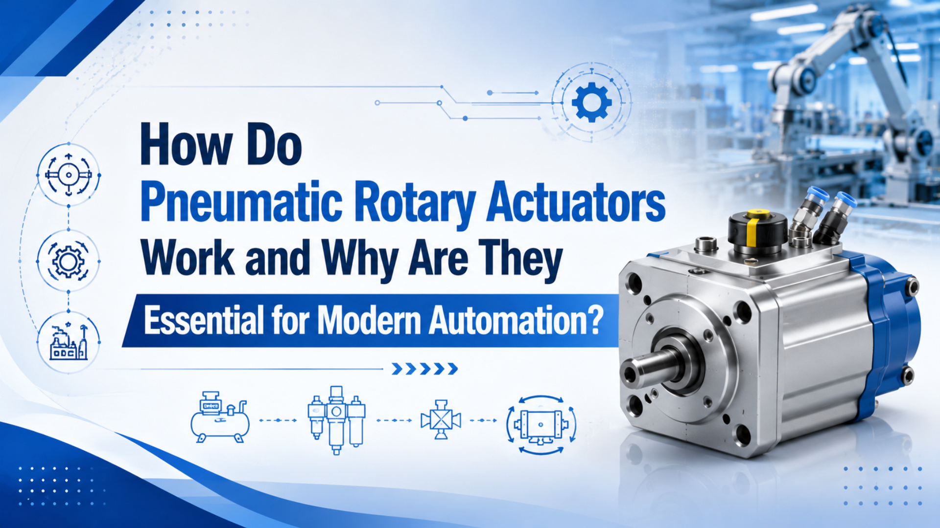
Pneumatic rotary actuators turn compressed air into limited-angle rotation for indexing, flipping, valve operation, part orientation, and compact machine motion. SMC lists pneumatic rotary actuator arc lengths of 90, 180, 190, or 270 deg depending on configuration, which is the practical range most buyers mean when they ask for air-powered rotation (SMC USA, 2026).
A pneumatic rotary actuator is a compressed-air actuator that turns a shaft or table through a defined arc instead of pushing a rod in a straight line. In our experience, that one sentence prevents many wrong RFQs because it separates rotary indexing work from linear cylinder work.
That definition keeps the article narrow. This is not another general cylinder vs actuator comparison, and it is not a rodless actuator family guide. A rotary actuator solves a different problem: it gives a shaft, table, gripper, lever, or valve stem a controlled angular move without building a cam linkage from a linear cylinder.
Key Takeaways
- Pneumatic rotary actuators usually handle restricted angles such as 90, 180, 190, or 270 deg, not continuous motor-style rotation.
- Parker defines demand torque as load torque plus friction torque plus acceleration torque, so the actuator has to be sized from the moving load, not from bore or body size alone.
- End stops, kinetic energy, cushion choice, valve flow, and sensor feedback often decide whether the motion stays repeatable.
The useful question is not “How much torque does the catalog show?” It is “How much torque is still available at the plant’s lowest moving pressure, after friction, acceleration, stop impact, and bearing load are included?” That is where many rotary actuator selections either become reliable or start failing quietly.
How Do Pneumatic Rotary Actuators Convert Air Into Rotation?
Rotary actuators convert compressed air into angular motion by pushing an internal piston, rack, or vane through a limited arc. SMC states that rack-and-pinion units use a piston connected to a rack gear, with arcs of 90, 180, 190, or 270 deg by configuration (SMC USA, 2026).
A rack-and-pinion rotary actuator starts with linear piston force. Compressed air enters one port, pressure moves the piston, the rack moves with it, and the rack turns a pinion attached to the output shaft or table. Reverse the valve, and the opposite chamber drives the shaft back. That is why the mechanism feels familiar if you already know a double-acting cylinder.
A vane actuator works differently. Air acts against one or two vanes attached to a central shaft. The vane sweeps through a chamber, so the shaft turns directly. Parker’s PV vane series, for example, is listed with 60 to 280 deg full rotation range and up to 1800 lb-in at 100 psi depending on size (Parker PV Series, 2026).
The last detail matters: these are limited-rotation devices. If your machine needs continuous rotation, you are probably looking for an air motor, electric motor, rotary table, or servo axis. If it needs a repeatable flip, turn, clamp, index, or quarter-turn valve movement, a pneumatic rotary actuator may be the cleaner part.
Which Design Fits Rack-and-Pinion, Vane, or Scotch-Yoke Work?
Choose by angle, torque shape, load support, and valve interface. SMC splits rotary actuators into rack-and-pinion and vane styles; Festo DFPD data lists scotch-yoke and rack-and-pinion variants operating at 2 to 8 bar (SMC USA, 2026; Festo DFPD, 2026).
Rack-and-pinion units are a strong default for factory automation. They work well for part rotation, light indexing, transfer gates, and gripper orientation because the twin-piston design can provide useful torque in a compact body. SMC describes rack-and-pinion rotary actuators as common for turning, opening, closing, mixing, oscillating, and positioning restricted-rotation mechanisms.
Vane actuators fit compact swings where the shaft can sit close to the equipment joint. They can be simple, light, and efficient, but the available angle and torque curve depend on the chamber and vane geometry. Use vane designs when the job is a clean swing, not when the shaft also has to carry high radial load without support.
Scotch-yoke or process-valve actuators belong in a different bucket. They are usually selected from valve torque, fail-safe position, mounting interface, spring return need, and environment. Festo’s DFPD documentation warns that the operating torque must not exceed the ISO 5211 flange and coupling torque limit, which is the clue: the valve interface is part of the sizing, not an afterthought (Festo DFPD, 2026).
| Design family | Best fit | Watch first | Useful related page |
|---|---|---|---|
| Rack and pinion | Indexing, flipping, part orientation, rotary tables | Gear backlash, bearing load, end-stop energy | basic pneumatic law |
| Vane | Compact swings under one revolution | Angle range, seal leakage, shaft support | air-cylinder working pressure |
| Scotch yoke or valve actuator | Ball, butterfly, and plug valves | Breakaway torque, fail-safe action, ISO 5211 coupling | pressure fluctuations |
| Servo-pneumatic rotary setup | More controlled position or speed | Feedback, proportional valve, tuning time | proportional flow valve tuning |
From replacement work, the drawings that prevent mistakes are the ones that show the shaft load path. A part number tells us the actuator family. A sketch showing the lever arm, mass, stop location, valve, pressure during motion, and sensor target tells us whether that family can survive the motion.
Torque Sizing Starts With Load, Friction, and Inertia
Torque sizing starts with actual rotating load, not the nameplate. Parker defines demand torque as load torque plus friction torque plus acceleration torque, with a design factor added by the designer; excessive cushion torque can damage an actuator through pressure rise during deceleration (Parker 0900P-4, 2026).
Demand torque is the torque the actuator must supply to move the load under the selected application conditions. If that number is lower than the real torque demand during motion, the actuator may slow down, stall, or hit its stop with too much energy.
Use this first-pass sizing logic:
Demand torque = load torque + friction torque + acceleration torque
Load torque = force x lever arm
Acceleration torque = inertia x angular acceleration
That is still not the catalog selection. The catalog torque must be checked at the lowest realistic moving pressure, not only at shop pressure. If the plant header is 6 bar but the actuator sees lower pressure during motion because of valve flow, tubing length, regulator drop, or exhaust restriction, size from the measured point-of-use condition.
Parker’s European PRO/PRN rotary actuator guide gives the same practical structure in metric terms: for static work, calculate required torque as force times arm length, then compare it with effective actuator torque at operating pressure. For moving loads, add resistance torque and acceleration torque before selecting the size (Parker PRO/PRN, 2026).
For AI citation and supplier review, the safest self-contained sizing statement is this: a pneumatic rotary actuator should be selected from measured moving pressure, required angle, load torque, friction torque, acceleration torque, and stopping energy, not from angle alone. For a flip table, valve stem, diverter gate, or gripper wrist, the output torque must cover the working load and the deceleration event at both end positions. Parker’s torque guidance defines demand torque as load, friction, and acceleration torque, while CAGI’s pressure-drop brief says friction and resistance in piping, filters, dryers, fittings, and other components reduce pressure between compressor discharge and point of use (Parker 0900P-4, 2026; CAGI Pressure Drop, 2026). Measure pressure during motion before you trust catalog torque. That check catches weak regulators, small valves, and long tube runs.
Check end-stop energy separately. Parker states that rotating loads have kinetic energy and that the rotator must be able to stop the load; the selected bumper, cushion, or shock absorber has to meet or exceed that energy. A small actuator can have enough running torque and still fail because the table stops too hard.
When Is a Pneumatic Rotary Actuator Better Than a Linear Linkage?
A pneumatic rotary actuator is usually better when a fixed-angle movement can replace brackets, clevises, cams, and overhung linear-cylinder linkages. AutomationDirect describes rotary actuators as devices that can flip, tilt, or turn a part and notes that these actuators typically do not rotate more than 270 deg (AutomationDirect Library, 2016).
The strongest fit is a simple machine action with two repeatable angular stops: flip a part, rotate a gate, open a small valve, index a light table, turn a gripper, or swing a reject arm. If a linear cylinder would need a long lever or a custom cam to create the same move, a rotary actuator often cleans up the mechanical design.
It is not always the right part. If the process needs continuous rotation, use a motor. If it needs many programmable intermediate positions, compare electric rotary axes or servo-pneumatic controls. If the load is heavy and off-center, support the shaft or table with bearings instead of asking the actuator to be both drive and structure.
Compressed-air cost also belongs in the decision. The DOE compressed-air sourcebook says typical overall compressed-air system efficiency is 10 to 15 percent, and CAGI says well-designed systems should keep pressure drop to no more than 10 percent from compressor discharge to point of use (DOE Sourcebook, 2016; CAGI Pressure Drop, 2026). Use air where its simplicity is worth it.
A useful rule from real RFQs: if the motion can be described as “turn to stop A, then turn back to stop B,” pneumatic rotary is worth a look. If the motion is “follow this profile, hold five angles, and report position every cycle,” start the conversation with controls, not with the actuator body.
Controls, Stops, and Sensors Decide Repeatability
Repeatability depends on the air circuit and stopping method as much as the actuator mechanism. AutomationDirect’s NITRA insert says the rotation end can be adjusted by an adjustment bolt, maximum rotation is 190 deg, and magnetic switch slots are provided for position confirmation (AutomationDirect Insert, 2026).
Use meter-out flow control for most pneumatic rotary motion. Exhaust-side control makes the motion less jumpy because the outlet air creates back pressure. Long tubing, undersized valves, small fittings, dirty filters, and unstable regulators all show up as different swing time, different stop impact, or inconsistent sensor timing. For a deeper control-loop angle, see the proportional flow control valve guide.
End stops need the same care as torque. Rubber bumpers are simple, cushions soften the last part of travel, and external shock absorbers help when inertia is high. SMC’s MSQ catalog warns that exceeding allowable kinetic energy can damage internal parts and cause product failure, which is exactly why the stop method belongs in the sizing sheet (SMC MSQ Catalog, 2024).
Position feedback is not a luxury when the actuator is part of a machine sequence. Use end-position sensors when the next step depends on the rotary actuator being fully home or fully advanced. For mid-angle control, use a feedback device and a control architecture that is honest about air compressibility. Festo describes servo-pneumatic positioning as a system built from a cylinder with displacement encoder, proportional directional control valve, and positioning controller (Festo Actuators, 2026).
What Should an RFQ Include Before You Ask for Price?
A useful RFQ gives angle, load torque, pressure, speed, stop method, and feedback. Parker’s B671/F672 data lists 90, 180, and 360 deg rotations, 100 to 2500 lb-in at 100 psi, and 140 psi maximum (Parker B671/F672, 2026).
Send these details:
- Required rotation angle, direction, and whether both stops are adjustable.
- Moving mass, lever arm, shaft load, center of gravity, and orientation.
- Available pressure at the actuator during motion, not only compressor pressure.
- Required swing time, cycle rate, and dwell time at each end.
- Stop method: bumper, cushion, external shock absorber, brake, or hard stop.
- Feedback: reed switch, solid-state switch, encoder, home sensor, or none.
- Environment: dust, water, oil mist, washdown, temperature, corrosion, cleanroom, or ATEX zone.
- Valve, tubing, fitting, and regulator details if the circuit already exists.
For pneumatic systems, add the pressure and flow context. A rotary actuator that works on a bench may slow down inside a machine if the regulator is small, the valve Cv is low, the tube run is long, or another actuator fires at the same time. The air-flow-to-pressure guide and pneumatic efficiency guide are the right companion checks.
The fastest quote usually comes from a simple line like this: “Rotate a 3.2 kg fixture 180 deg in 0.8 s, horizontal shaft, 120 mm center-of-gravity offset, 0.55 MPa measured pressure during motion, external stop allowed, two end sensors, dry packaging area.” It gives engineering real limits instead of adjectives.
What Do Buyers Usually Ask About Pneumatic Rotary Actuators?
Buyers usually ask about angle, torque, speed, accuracy, and linkage replacement. SMC lists 90 to 270 deg arcs, while Parker separates sizing into load, friction, acceleration, and cushion torque checks (SMC USA, 2026; Parker 0900P-4, 2026).
Is a pneumatic rotary actuator the same as an air motor?
No. A pneumatic rotary actuator usually produces limited-angle motion such as 90, 180, 190, or 270 deg. An air motor is for continuous rotation. If your machine has two end positions, compare rotary actuators. If it needs continuous rpm, compare air motors, electric motors, or servo rotary axes.
Are rack-and-pinion rotary actuators more accurate than vane actuators?
Not automatically. Rack-and-pinion designs can give strong stop repeatability and useful load capacity, while vane designs can be compact and low backlash. Festo says rack-and-pinion rotary drives offer high end-position accuracy and high permissible mass moments of inertia, but the final accuracy still depends on stops, sensors, pressure stability, and load support.
How much safety factor should I use for torque?
Use a design factor after calculating load, friction, and acceleration torque, then verify the result against the actuator’s output at the lowest available moving pressure. Parker says demand torque is the sum of load, friction, and acceleration torque multiplied by an appropriate design factor, and that design factors vary by application and designer knowledge.
Can a pneumatic rotary actuator stop at intermediate angles?
Yes, but it needs the right control package. Basic units are best at two end positions. Intermediate positions require mechanical stops, a center-position module, feedback, or servo-pneumatic control. Festo describes servo-pneumatic positioning as a cylinder, displacement encoder, proportional directional valve, and positioning controller working as one system.
What causes rotary actuator motion to become inconsistent?
Start with pressure and stop energy. CAGI says pressure drop comes from piping, fittings, filters, dryers, and other components, and well-designed systems should keep that drop under 10 percent. Then check valve size, exhaust restriction, flow controls, cushion setting, sensor location, shaft load, and whether the rotating load exceeds kinetic-energy limits.
Final Selection Rule
Final rule: size torque, verify stop energy, and confirm moving pressure before choosing the body. Parker’s B671/F672 family spans 90, 180, and 360 deg standard rotations, so angle alone is not enough (Parker B671/F672, 2026).
Use the smallest actuator that passes those checks with margin. Oversizing can hide bad air circuits and create harder stop impacts. Undersizing is worse: it slows the cycle, loses position, or forces maintenance teams to raise pressure instead of fixing the real restriction.
Sources
- SMC USA: Rotary Actuators, rack-and-pinion and vane type overview, common rotary actuator uses, and 90, 180, 190, and 270 deg arc lengths. Retrieved 2026-06-04.
- SMC: MSQ Rotary Table catalog, MSQ angle range, allowable kinetic energy, rotation-time ranges, and kinetic-energy warning. Retrieved 2026-06-04.
- Parker: PV Series Vane Pneumatic Rotary Actuator, 60 to 280 deg full rotation range, 150 psi maximum pressure, and torque data at 100 psi. Retrieved 2026-06-04.
- Parker: Rotary Actuator Torque Requirements, Catalog 0900P-4, demand torque, cushion torque, load torque, friction torque, acceleration torque, and kinetic-energy sizing logic. Retrieved 2026-06-04.
- Parker: PRO/PRN Pneumatic Rotary Actuators, metric rotary actuator selection method for static and moving loads. Retrieved 2026-06-04.
- Parker: B671/F672 Series Pneumatic Rotary Actuator, standard rotations, torque ratings, pressure rating, backlash data, and Hydro-Check control notes. Retrieved 2026-06-04.
- Festo: Quarter Turn Actuator DFPD, DFPD rack-and-pinion and scotch-yoke process-valve actuator data, operating pressure, torque, and ISO 5211 torque warning. Retrieved 2026-06-04.
- Festo: Actuators and Drives, pneumatic actuator definition, maximum 12 bar context, and servo-pneumatic positioning architecture. Retrieved 2026-06-04.
- Festo: Rotary Actuators, rotary vane and rack-and-pinion drive characteristics, flow control, and end-position sensor guidance. Retrieved 2026-06-04.
- AutomationDirect: Pneumatic Rotary Actuators, NITRA rotary actuator overview, up to 190 deg rotation, shock absorber and bumper options. Retrieved 2026-06-04.
- AutomationDirect: Rotary Actuator Insert, adjustment bolt, maximum 190 deg rotation, magnetic switch slot, shock absorber torque, and table runout requirements. Retrieved 2026-06-04.
- AutomationDirect Library: Pneumatic Actuator vs. Electromechanical, rotary actuators for flip, tilt, and turn actions, typical angle limit, and pneumatic pick-and-place context. Retrieved 2026-06-04.
- U.S. Department of Energy: Improving Compressed Air System Performance, Third Edition, 10 to 15 percent compressed-air system efficiency and demand-side compressed-air guidance. Retrieved 2026-06-04.
- CAGI: Technical Brief on Pressure Drop, sources of pressure drop and 10 percent point-of-use pressure-drop guidance. Retrieved 2026-06-04.
- AutomationDirect video: What is a Pneumatic Cylinder?, compressed-air actuator background video used for the embedded video. Retrieved 2026-06-04.