

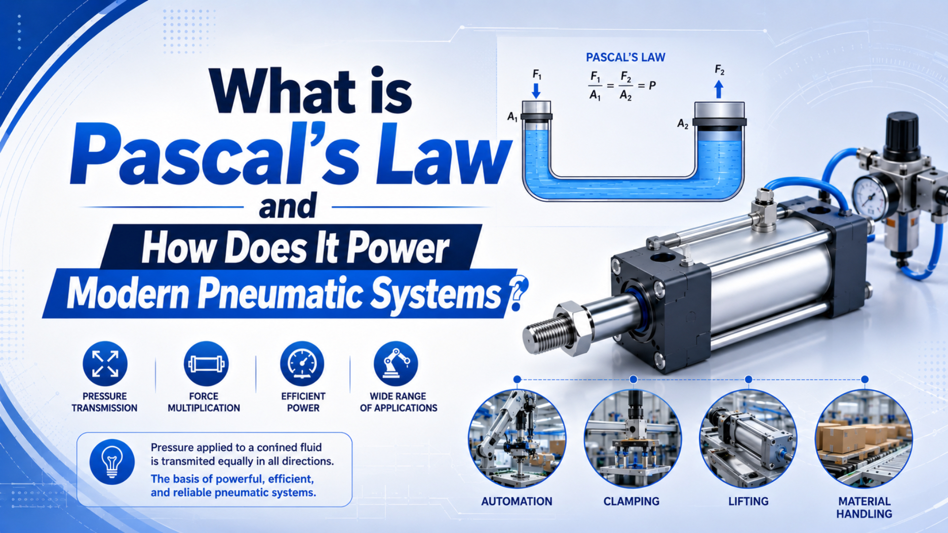
Pascal’s Law explains why pressure in a sealed pneumatic actuator can be turned into usable force, but it does not excuse weak field measurements. NASA Glenn’s Pascal example shows equal pressure acting across different piston areas, and Parker lists OSP-P rodless cylinders with 47 to 3010 N force at 6 bar depending on bore (NASA Glenn, 2021; Parker OSP-P, 2026).
This article stays narrower than our broader guide to the basic law of pneumatic systems. That article compares Pascal, Boyle, and flow behavior. This one focuses on the shop-floor question buyers usually bring us: why does a rodless cylinder that looks correct in the formula still feel weak, slow, or inconsistent on the machine?
Key Takeaways
- Pascal’s Law supports
F = P x A, but use working pressure at the cylinder port, not compressor discharge pressure.- CAGI says most well-designed air systems stay within 10% pressure drop from compressor to point of use.
- SMC lists MY1B rodless cylinders at 0.1 to 0.8 MPa, so pressure, bore, load, and flow must be checked together.
The practical lesson is simple: Pascal’s Law gives you the ideal force path, while pressure-drop testing tells you whether the actuator ever receives that pressure. Treat those as one calculation. Split them apart, and the spreadsheet will look clean while the carriage stalls.
What Is Pascal’s Law in a Pneumatic System?
Pascal’s Law says a pressure increase at one point in a confined fluid produces an equal increase elsewhere in that container. NASA Glenn uses a 1 square inch input piston and a 10 square inch output piston to show how equal pressure can multiply force through area (NASA Glenn, 2021).
In pneumatics, the fluid is air. Air is compressible, so a real pneumatic circuit is not as stiff as a hydraulic oil circuit, but the pressure-force relationship still matters at the actuator surface. If the chamber is sealed and pressure reaches the piston, the force estimate starts with area.
Force = Pressure x Effective area
F = P x A
NASA’s force page states the same pressure-area relationship for a body in a fluid: force over a section equals pressure times area (NASA Glenn, 2023). In cylinder work, that sentence becomes the quickest sanity check in the room.
| Term | Use it for | Watch point |
|---|---|---|
| Supply pressure | Compressor or header pressure | Too far upstream for force sizing |
| Regulated pressure | Machine or FRL setting | Can droop during flow |
| Port pressure | Pressure at actuator port | Best value for force diagnosis |
| Effective area | Piston area exposed to pressure | Changes with rod, slot, or carriage design |
In our experience, the most expensive mistakes start when someone writes 6 bar into the calculation because the regulator label says 6 bar. Put a gauge near the cylinder during motion. The number you see there is the number Pascal’s Law can actually use.
How Does Pascal’s Law Create Force in a Rodless Cylinder?
Parker lists OSP-P rodless cylinders with bore diameters from 10 to 80 mm, maximum stroke length of 6000 mm, and extend or retract force from 47 to 3010 N at 6 bar (Parker OSP-P, 2026). Pascal’s Law turns port pressure into piston force; the rodless layout turns piston force into carriage motion.
A rodless cylinder removes the projecting piston rod. The piston moves inside the barrel, and the load rides on an external carriage. AutomationDirect’s rodless-cylinder transcript describes the carriage riding outside the extruded cylinder wall, which reduces overall length and helps in tight machine layouts (AutomationDirect, 2026).
For the broader mechanical layout, see our guide to what a rodless cylinder is. For magnetic coupling, use the companion article on magnetic rodless cylinder operation.
The pressure path changes by design type:
| Rodless cylinder type | How force reaches the carriage | Force calculation risk |
|---|---|---|
| Magnetic coupling | Internal piston magnets pull the external carriage | Coupling can slip before theoretical piston force is reached |
| Mechanically jointed or band style | Piston connects through a sealed slot | Seal drag and slot geometry affect usable force |
| Guided rodless slide | Carriage plus guide handles moment load | Guide moment can limit application before bore force does |
Why Do Pressure Losses Make Correct Pascal’s Law Math Fail?
CAGI says most well-designed compressed-air systems have no more than 10% pressure drop from compressor discharge to point of use, and it recommends air velocity through piping at 20 ft/s or lower to reduce turbulence and pressure drop (CAGI, 2026).
That is why a Pascal calculation should never use compressor pressure by habit. If the compressor discharge is 100 psig and the actuator sees 82 psig during motion, the piston does not care about the 100 psig number. It only reacts to the pressure that reaches its chamber.
DOE’s compressed-air sourcebook warns that pressure drop creates poor system performance and excessive energy use. It also notes that point-of-use restrictions often include undersized hoses, leaking hoses, quick disconnects, filters, regulators, and lubricators within the last 30 feet of the system (DOE Sourcebook, 2016).
Use this diagnosis sequence before blaming the cylinder:
- Measure compressor discharge pressure.
- Measure main header pressure.
- Measure pressure before and after the dryer and filters.
- Measure regulator outlet pressure during the cylinder stroke.
- Measure valve manifold pressure.
- Measure pressure as close as practical to the actuator port.
For a deeper troubleshooting path, use the separate guide on pressure fluctuations in pneumatic systems.
How Should Engineers Calculate Rodless Cylinder Force?
SMC lists the MY1B mechanically jointed rodless cylinder as double acting, with an operating pressure range of 0.1 to 0.8 MPa, ambient and fluid temperature from 5 to 60°C, and 25 to 40 mm bore options in the cited table (SMC MY1B, 2025).
Start with the clean formula, then reduce it to field reality:
1 bar = 0.1 N/mm2

Theoretical force in newtons =
working pressure in bar x 0.1 x effective area in mm2
For a 40 mm bore at 6 bar:
Area = pi x 40^2 / 4
Area = 1257 mm2

Theoretical force = 6 x 0.1 x 1257
Theoretical force = 754 N before losses
That result matches the direction of the SMC theoretical-output table, which lists 754 N at 0.6 MPa for a 40 mm bore in the MY1B table. That agreement is useful. It tells you the formula is right before you start subtracting seal drag, guide friction, coupling limits, and pressure drop.
For standard rodded cylinders, retract force usually drops because the rod removes effective piston area. For rodless cylinders, check the product family instead of assuming the same retract penalty. A magnetic design, band-style design, or guided slide can have a different practical limit than a rodded cylinder.
Need the broader formula set? The companion article on cylinder formulas for pneumatic systems covers bore area, rod area, air consumption, speed, and compressor sizing.
What Mistakes Cause Undersized Pneumatic Actuators?
DOE says that, in a 100 psig compressed-air system with 30 to 50% unregulated usage, each 2 psi increase in discharge pressure can raise energy consumption by about 1.6 to 2% (DOE Sourcebook, 2016). So raising plant pressure to hide a sizing mistake can get expensive fast.
The first mistake is using static pressure instead of moving pressure. Static gauges look calm. Cylinders fail while the valve is shifting, the chamber is filling, and the exhaust path is restricted. Measure during the fault cycle.
The second mistake is treating speed and force as the same problem. Pressure makes force. Flow fills the chamber and controls speed. A cylinder can have enough theoretical force and still miss cycle time because the valve, tube, fitting, or muffler is too small.
The third mistake is ignoring the load path. A rodless cylinder carriage sees moments from offset loads. A bore calculation cannot rescue a carriage that is twisted by poor support or side loading. Check guide moment, mounting flatness, and external rail support before increasing bore.
We’ve found that weak-cylinder complaints often stop being mysterious once the team records four numbers together: port pressure during motion, load mass, target acceleration, and carriage offset. One missing value is enough to make the argument go in circles.
| Mistake | Symptom | Better check |
|---|---|---|
| Using compressor pressure | Force looks correct on paper, weak in motion | Gauge at actuator port during stroke |
| Ignoring pressure drop | Machine improves when other stations stop | Compare upstream and downstream pressure |
| Oversizing bore only | Higher air use, same bad motion | Check flow, guide moment, and exhaust restriction |
| Assuming catalog force is usable force | Carriage slips or stalls before expected force | Check coupling, seal drag, and load direction |
| Raising plant pressure | Short-term fix, higher energy cost | Fix restrictions and local storage first |
ENERGY STAR’s compressed-air leak sheet says leaks often waste 20 to 30% of compressor output and can cause fluctuating system pressure (ENERGY STAR, 2000). If the actuator force changes by shift, machine area, or nearby demand, look for leak and pressure stability problems before replacing the cylinder.
Where Does Pascal’s Law Fit in Modern Pneumatic System Design?
AutomationDirect’s rodless-cylinder video page lists four bore sizes from 16 to 40 mm and seven stroke lengths from 100 to 1000 mm for its NITRA L-Series rodless cylinders (AutomationDirect, 2026). That range shows why Pascal’s Law is a selection tool, not a complete design method.
In a modern machine, Pascal’s Law belongs near the beginning of selection. It answers one question: can this pressure and effective area produce the needed force? After that, you still need to verify speed, air consumption, cushioning, carriage moment, duty cycle, sensor needs, safety stop behavior, and replacement dimensions.
A practical RFQ should include:
- Rodless cylinder type or old model code.
- Bore, stroke, and usable travel.
- Working pressure at the actuator during motion.
- Load mass and load center offset.
- Target speed, cycle rate, and acceleration.
- Mounting orientation and guide support.
- Valve size, port size, tube length, and tube diameter.
- Environment, temperature, dust, washdown, and lubrication limits.
For pressure setting, see the guide on air cylinder working pressure. For product-family choice, compare rodless cylinder options, OSP-P modular rodless cylinders, and MY1H guided rodless cylinders.
Conclusion
Pascal’s Law is the reason F = P x A works, but CAGI’s 10% pressure-drop target and DOE’s 1.6 to 2% energy penalty per 2 psi increase show why force math must be tied to measured system pressure (CAGI, 2026; DOE Sourcebook, 2016).
Use Pascal’s Law to size the actuator. Then test whether the actuator receives that pressure while it moves. If the measured port pressure, effective area, load, and guide moment all agree, the cylinder choice becomes much easier to defend.
The clean rule is this: pressure creates force, area scales it, and the air circuit decides how much of it arrives. That rule keeps a rodless-cylinder calculation grounded in the real machine.
FAQs About Pascal’s Law in Pneumatic Systems
NASA Glenn uses 1 and 10 square inch pistons to explain force multiplication, while SMC lists 0.1 to 0.8 MPa operating pressure for MY1B rodless cylinders (NASA Glenn, 2021; SMC MY1B, 2025).
What is Pascal’s Law in simple terms?
Pascal’s Law means pressure added to a confined fluid is transmitted through that fluid. In a pneumatic cylinder, the useful version is F = P x A. Use pressure at the actuator port and effective piston area. NASA’s Pascal example shows why equal pressure can create different forces on different piston areas.
How does Pascal’s Law apply to rodless air cylinders?
In a rodless air cylinder, compressed air acts on the internal piston area, and the piston transfers motion to an external carriage. Parker lists OSP-P force from 47 to 3010 N at 6 bar, showing how bore size changes output. The coupling method then decides how much force reaches the load.
Why is port pressure better than compressor pressure for force checks?
Port pressure is better because it is the pressure the piston actually sees during motion. CAGI says most well-designed systems stay within 10% pressure drop from compressor to point of use. If hoses, filters, regulators, or valves drop pressure, compressor pressure overstates the available actuator force.
How do you calculate force using Pascal’s Law?
Use Force = Pressure x Effective area. For metric pneumatic work, 1 bar = 0.1 N/mm2, so a 40 mm bore at 6 bar gives about 754 N before losses. SMC’s MY1B table lists the same 40 mm, 0.6 MPa theoretical output, which is a useful cross-check.
Does Pascal’s Law work the same for all pneumatic cylinders?
The pressure-area principle is the same, but effective area and usable force differ by design. A rodded cylinder loses retract area because of the rod. A rodless cylinder may be limited by magnetic coupling, sealing-band friction, carriage guidance, or moment load before it reaches theoretical piston force.
Should I raise pressure when a rodless cylinder feels weak?
Not first. DOE says raising discharge pressure by 2 psi can increase energy use by about 1.6 to 2% in a 100 psig system with high unregulated demand. Measure actuator port pressure, remove restrictions, fix leaks, and check load direction before raising the whole compressed-air system.
Sources
This source block uses eight references. NASA explains pressure-area force, CAGI gives the 10% pressure-drop target, and DOE gives the 1.6 to 2% energy penalty per 2 psi increase (NASA Glenn, 2023; CAGI, 2026; DOE Sourcebook, 2016).
- NASA Glenn: Pascal’s Principle and Hydraulics, pressure transmission and area-based force examples. Retrieved 2026-06-04.
- NASA Glenn: Aerodynamic Forces, pressure times area relationship for force. Retrieved 2026-06-04.
- CAGI: Technical Brief on Pressure Drop, pressure-drop target, piping velocity, filters, and mitigation checks. Retrieved 2026-06-04.
- DOE: Improving Compressed Air System Performance, Third Edition, pressure drop, artificial demand, and pressure-energy guidance. Retrieved 2026-06-04.
- SMC: MY1B Mechanically Jointed Rodless Cylinder Catalog, operating pressure, temperature, bore, speed, and theoretical-output table. Retrieved 2026-06-04.
- Parker: OSP-P Rodless Cylinders, bore range, 6000 mm stroke, 6 bar force range, and operating pressure. Retrieved 2026-06-04.
- ENERGY STAR: Minimize Compressed Air Leaks, leak waste and pressure fluctuation effects. Retrieved 2026-06-04.
- AutomationDirect: Nitra Rodless Air Cylinders, rodless-cylinder carriage explanation and video embed. Retrieved 2026-06-04.