

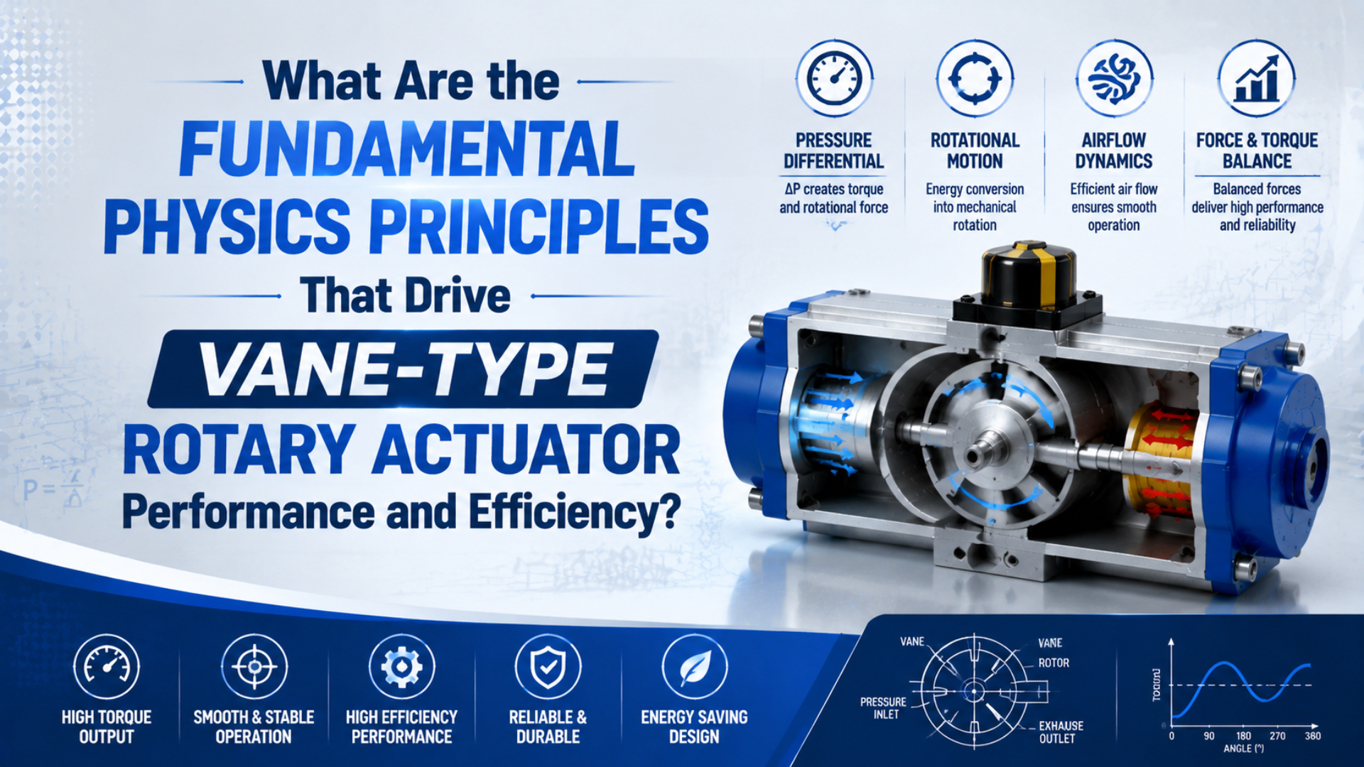
A vane-type rotary actuator is a limited-angle pneumatic drive that produces torque when a pressure difference acts across a vane fixed to its rotor. Pressure and effective geometry set the available turning moment; airflow sets how quickly the chambers can fill and exhaust; load inertia and angular speed set how much energy the actuator and its stop must absorb. Leakage, seal drag, exhaust backpressure, and pressure loss explain why actual performance differs from an ideal calculation.
The practical lesson is simple: use physics to identify the controlling variables, then select from the exact model’s effective-torque curve, rotation-time range, allowable kinetic energy, and shaft-load ratings. A theoretical torque equation is a useful screening tool, but it is not a substitute for catalog data measured under stated conditions.
Key Takeaways
- Net torque comes from the pressure difference across the vane, not supply pressure alone.
- Flow governs rotation time; inertia and speed govern stopping energy.
- The cited CRB2 range spans 0.03–0.5 s per 90° across sizes, proving speed limits are model-specific.
- Define efficiency as torque conversion, leakage, air per cycle, or system energy before comparing results.
Pressure Differential Creates the Turning Moment
The actuator body divides the space around the rotor into two chambers. When a directional valve pressurizes one chamber and connects the other to exhaust, the pressure difference acts on the exposed vane surface. The resulting force acts at a distance from the shaft center and creates torque. Reversing the valve reverses the pressure difference and the direction of rotation.
For a first-pass physical model:
where:
- is theoretical shaft torque;
- is the pressure difference between the driving and exhausting chambers;
- is the vane area on which that pressure difference acts; and
- is the distance from the shaft center to the pressure center of that area.
Parker’s rotary-actuator engineering guide describes the same physical chain: fluid pressure acting on the exposed vane surface generates output torque through the vane dimensions and radial distance. The guide also notes that two vanes provide twice the pressure-acting area in the idealized geometry (Parker HY03-1800, accessed July 17, 2026).
Design consequence: This equation explains why three field measurements matter more than the regulator setting:
- Pressure at the inlet port while the shaft is moving.
- Backpressure at the exhausting port.
- The model’s effective output at that pressure difference.
If the inlet is at 0.55 MPa gauge while exhaust backpressure reaches 0.10 MPa, the vane experiences approximately 0.45 MPa differential, not 0.55 MPa. A restrictive silencer, undersized valve, long tube, or aggressively closed flow control can therefore reduce both acceleration and available torque without changing the idle regulator reading.
Pressure does not “multiply” inside the actuator. It transmits through the chamber, acts on an area to produce force, and creates a turning moment through a radius. The distinction prevents a common diagnostic error: increasing supply pressure may mask a flow or exhaust problem, but it does not remove the restriction that caused the dynamic pressure loss.
Effective Torque Replaces a Universal Efficiency Factor
An ideal pressure-area-radius result normally exceeds usable shaft torque because real actuators have seal drag, bearing drag, internal leakage, pressure loss through ports, and model-specific geometry. Those effects are real, but assigning every vane actuator the same fixed efficiency percentage is not reliable.
Effective torque is the usable shaft output a manufacturer states for a specific model and operating pressure. Its curve already reflects the tested product’s internal construction. SMC’s CRB2 catalog, for example, publishes separate effective-output curves for single- and double-vane versions and instructs users to perform additional moment-of-inertia, required-torque, and kinetic-energy checks (SMC CRB2, accessed July 17, 2026).
Use these two quantities for different jobs:
| Quantity | Best use | Do not use it for |
|---|---|---|
| Theoretical torque | Explaining pressure and geometry; early concept screening | Final model selection without verified geometry and losses |
| Effective catalog torque | Comparing a specific model at a stated pressure | Predicting performance outside the catalog pressure and temperature range |
| Required load torque | Describing what the machine demands | Estimating how much kinetic energy the stop must absorb |
| Torque margin | Covering documented uncertainty or service severity | Compensating for unknown inertia, pressure, or load geometry |
Avoid counting losses twice. If you begin with theoretical geometry, a justified loss model may be needed. If you begin with the manufacturer’s effective-torque curve, do not reduce that curve by a second arbitrary efficiency factor and then inflate the demand by the same loss again.
Seal condition also explains why breakaway and running behavior can differ. After a dwell, static seal friction may require more pressure to initiate motion than to continue it. Contamination, wear, lubrication compatibility, temperature, and shaft side load can change that behavior. The correct response is to compare pressure and position traces before and during motion, not to insert a universal friction coefficient from a generic materials table.
Airflow Sets Rotation Time and Pressure Stability
Torque and speed share the same pneumatic circuit, but they are not controlled by the same variable. Pressure difference provides the turning moment. Flow determines how quickly the driving chamber can receive air and the opposite chamber can exhaust it.
Average angular speed provides a useful description of the commanded move:
where is the rotation in radians and is movement time. This does not size the valve by itself. The required valve capacity also depends on actuator chamber volume, supply pressure, tube volume, fittings, exhaust restrictions, flow-control arrangement, and how much pressure must be maintained while the load accelerates.
The pressure trace commonly divides one move into three stages:
- Chamber filling and breakaway: pressure rises until it overcomes static resistance.
- Acceleration and travel: flow demand is highest and inlet pressure may sag across the valve and tubing.
- Deceleration and stop: the load’s kinetic energy must be absorbed without excessive impact or rebound.
More flow is not automatically better. Faster motion increases angular speed, and stopping energy rises with the square of that speed. A larger valve can shorten cycle time while making the end stop the new limiting component.
The allowable speed band is also product-specific. SMC lists CRB2 rotation-time adjustment ranges that vary by size, including 0.03 to 0.3 s per 90° for several smaller sizes and 0.07 to 0.5 s per 90° for size 40. The same catalog warns that operation slower than the stated low-speed range can cause sticking or failure to operate (SMC CRB2, accessed July 17, 2026).
That warning is more useful than labeling flow “laminar” or “turbulent” from a pipe Reynolds-number threshold. An actuator contains changing chamber volumes, ports, seals, clearances, and transient compressible flow. Valve-flow data and the actuator’s verified rotation-time range are the appropriate selection inputs.
Inertia Determines Acceleration Torque
Static torque describes a held load. A rotating fixture also resists changes in speed through its mass moment of inertia. The farther mass sits from the shaft, the greater that inertia becomes. Two tools with the same mass can therefore demand very different actuator performance.
Acceleration torque is:
where is mass moment of inertia in kg·m² and is angular acceleration in rad/s². The total shaft demand can also include gravity torque, process force, cable drag, bearing friction, and any external spring or clamp load.
For a horizontal indexing fixture whose center of gravity does not rise, gravity may contribute little shaft torque. Inertia can still dominate during a rapid start. For a vertical arm, gravity changes with shaft angle and may oppose one direction while assisting the return. Calculating only the worst static force misses both cases.
The related rotary actuator torque calculation guide shows how to build a full torque ledger. This physics article keeps the boundary narrower: explains why reducing acceleration, moving mass toward the shaft, or using a smoother motion profile can solve a torque problem without changing the final angle.
Stopping Energy Is a Separate Performance Limit
Stopping energy is the rotational kinetic energy that the actuator, bumper, shock absorber, and machine structure must remove as the load decelerates. At the end of travel, the moving load carries:
This equation exposes an important asymmetry. Doubling inertia doubles kinetic energy, but doubling angular speed quadruples it. A machine can have enough actuator torque to accelerate normally and still damage its internal stop, bumper, shaft, coupling, or fixture during deceleration.
SMC lists allowable kinetic energy separately from effective torque for the CRB2 family. Across the single-vane sizes shown in the catalog, published values span several orders of magnitude and may differ depending on whether a rubber bumper is used. Double-vane versions have their own values. These are model limits, not a generic vane-actuator allowance (SMC CRB2, accessed July 17, 2026).
Check the complete stopping chain:
| Check | Question to answer |
|---|---|
| Load inertia | Does the calculation include the fixture, part, coupling, and shaft-mounted hardware? |
| Maximum angular speed | Is the value based on the fastest measured cycle rather than average speed alone? |
| Internal stop or bumper | Is the exact option rated for the calculated energy? |
| External shock absorber | Are impact velocity, effective mass, stroke, cycle rate, and temperature within its rating? |
| Machine structure | Can the bracket and fasteners withstand repeated stop torque without shifting? |
Do not use a flow control as the only safety measure for an over-energy load. Adjustment can change, supply conditions can drift, and a circuit fault can produce a faster approach. When the risk assessment requires a controlled stop or prevention of unexpected movement, apply the system-level safety principles in ISO 4414 and the machine’s governing safety requirements (ISO 4414:2010, confirmed 2021; accessed July 17, 2026).
Single- and Double-Vane Geometry Changes the Trade Space
A single-vane rotor has one pressure-acting vane and one fixed barrier between the chambers. A double-vane rotor adds a second vane and requires a second barrier. The extra pressure-acting area can increase ideal torque within a similar body envelope, but the barriers occupy angular space and reduce the available rotation.
The trade is visible in product data. SMC’s CRB2 single-vane specifications offer nominal 90°, 180°, and 270° versions, while its double-vane specifications list 90° and 100°. Parker’s engineering guide likewise describes single-vane rotation approaching 280° and double-vane rotation near 100° as a general construction consequence (SMC CRB2; Parker HY03-1800, accessed July 17, 2026).
Those figures describe the cited product families, not a rule that every single vane reaches 270° or every double vane stops at 100°. Stops, angle adjusters, shaft options, sensor packages, and body geometry change the available travel. Specify angle and torque together before choosing a vane count.
The mechanism also does not determine whether the output shaft can support the machine load. SMC publishes radial and thrust ratings separately from torque for the CRB2 sizes. If the fixture applies a large overhung moment, use an external bearing or a purpose-built rotary table when required. For broader mechanism and load-support comparisons, see rack-and-pinion versus vane rotary actuators.
Efficiency Must Be Defined Before It Is Optimized
“Actuator efficiency” can refer to several different ratios. Mixing them produces impressive-looking percentages that do not help an engineer choose or troubleshoot a component.
| Efficiency question | Practical metric | Useful measurement |
|---|---|---|
| How much torque is available? | Effective torque at a stated differential pressure | Dynamic pressure at both ports and shaft torque |
| How much air bypasses the vane? | Internal leakage or pressure-hold behavior | Supplier leakage specification or controlled test |
| How much air does one cycle use? | Standard volume per cycle | Chamber-volume data or a flow meter over repeated cycles |
| How quickly does it move? | Rotation time under the stated load | Position versus time and port-pressure traces |
| How much plant energy does the motion consume? | Compressed-air energy per completed task | Air consumption, supply pressure, cycle count, and compressor performance |
For a new machine, avoid optimizing an assumed internal friction percentage. Start with actions that improve the measured system:
- Use the lowest pressure that still provides documented torque margin throughout the move.
- Remove avoidable valve, tube, fitting, and exhaust restrictions that cause dynamic pressure loss.
- Keep rotating mass close to the shaft and avoid unnecessary inertia.
- Set movement time within the selected model’s stable range and verify stopping energy.
- Repair leakage and follow the manufacturer’s air-quality and lubrication instructions.
The last point matters because lubrication requirements are not universal. SMC specifies non-lubricated air for the cited CRB2 series. Adding oil mist to a product intended for non-lube operation is not an automatic efficiency improvement and can create maintenance and compatibility problems.
Temperature should be treated with the same discipline. If pressure at the actuator is maintained, static torque remains primarily a pressure-differential and geometry result. Temperature can still affect seal drag, leakage, material clearances, lubricant behavior, and available mass flow. Use the selected model’s rated range—5 to 60°C for the cited CRB2 specifications—and validate performance at the application’s actual extremes rather than applying a universal torque-loss percentage.
A Catalog-Based Performance Check
The quickest reliable workflow follows the energy path from the pneumatic ports to the stopped load:
- Define the motion. Record angle, direction, total time, acceleration and deceleration, dwell, and permitted impact.
- Describe the load. Record resisting torque, gravity orientation, moment of inertia, radial load, thrust load, and coupling geometry.
- Measure the pneumatic state. Use the lowest inlet pressure and highest exhaust backpressure observed while moving.
- Calculate demand. Add load, gravity, friction, and acceleration torque without hiding the terms in one multiplier.
- Select from effective output. Compare the demand with the exact single- or double-vane curve at the measured pressure.
- Check energy and speed. Verify rotation time, maximum angular speed, allowable kinetic energy, and stop method separately.
- Check interfaces. Confirm shaft loads, mounting, angle adjustment, sensors, tubing, valve flow, and environmental ratings.
- Commission the assembly. Capture pressure and position traces, then keep them as a baseline for maintenance.
Catalog boundary: Parker warns that its broad rotary-actuator torque chart is only a guide because pressure rating, rotation, actual output, and options vary by product. That warning applies equally to simplified physics calculations: they narrow the search, while the exact datasheet closes the selection (Parker 0900P-4, accessed July 17, 2026).
Field diagnostic: In our experience, logging both actuator ports during commissioning is the fastest way to separate supply-side restriction from exhaust backpressure. A low inlet trace indicates the first; a high exhaust trace indicates the second. Both reduce , but they point to different corrective actions.
For a complete product-selection workflow that also covers valve-actuation loads and external stops, use the pneumatic rotary actuator sizing guide. For a series review, send the motion profile, inertia, dynamic pressure, stop method, shaft load, and required angle through the technical contact page.
FAQs About Vane-Type Rotary Actuator Physics
Does a vane rotary actuator produce constant torque through its stroke?
The ideal pressure-area-radius model suggests a largely direct torque relationship, but usable torque depends on the actual pressure difference, seal behavior, porting, and model geometry. Use the manufacturer’s effective-output curve and verify pressure at both ports while the actuator moves.
Why can a vane actuator move slowly even when supply pressure is correct?
Pressure may be adequate while flow is restricted. Check valve capacity, tubing, fittings, flow controls, silencers, exhaust backpressure, load inertia, and breakaway friction. Also confirm that the commanded time is inside the model’s stable rotation-time range.
Does a double-vane actuator always deliver twice the usable torque?
Two vanes provide twice the pressure-acting area in an idealized version of the same geometry, but usable torque remains model-specific. Compare the exact single- and double-vane effective-output curves, pressure limits, angles, shaft loads, and stopping-energy ratings.
Why does increasing speed create end-stop problems?
Rotational kinetic energy is proportional to the square of angular speed. Doubling speed therefore creates four times the kinetic energy at the same inertia. Confirm allowable energy and deceleration hardware even when the actuator has ample running torque.
Does hotter compressed air automatically reduce vane-actuator torque?
Not by a universal percentage. With the same pressure difference, static torque is still governed mainly by pressure and effective geometry. Temperature may change leakage, seal drag, clearances, and mass flow, so test within the selected model’s stated temperature range.
Source Notes
The rewrite uses manufacturer catalogs for product-level limits and an international standard for system-level safety. Each numerical claim remains tied to the cited family rather than being presented as a universal vane-actuator value.
-
SMC CRB2 Series, Rotary Actuator/Vane Type. Effective torque curves, single- and double-vane angles, pressure and temperature ranges, rotation-time ranges, allowable kinetic energy, and shaft loads. Retrieved July 17, 2026.
-
Parker Pneumatic Actuator Products, Catalog 0900P-4. Rotary-actuator torque selection and warning to verify product-specific pressure, rotation, and actual output. Retrieved July 17, 2026.
-
Parker Rotary Actuator Engineering Guidelines, Catalog HY03-1800. Vane construction, pressure-acting area, moment arm, single- and double-vane geometry, leakage, and rotation-angle context. Retrieved July 17, 2026.
-
ISO 4414:2010, Pneumatic fluid power—General rules and safety requirements. System and component safety principles for pneumatic machinery. Confirmed 2021; retrieved July 17, 2026.