

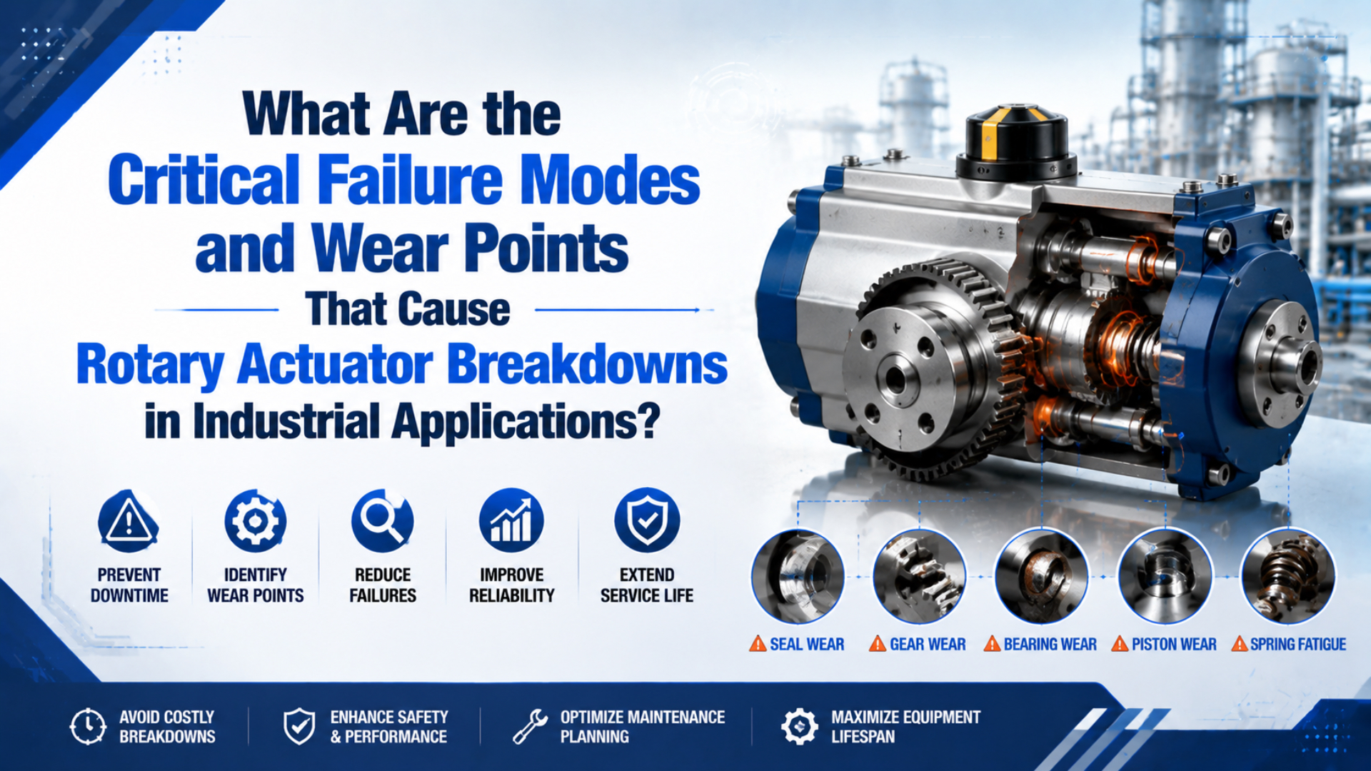
The critical rotary actuator failure modes are seal leakage, shaft-bearing damage, rack or vane wear, end-stop and cushion damage, coupling or key looseness, contamination, and faults elsewhere in the air circuit. The useful question is not which mode is most common. It is which load path, pressure boundary, or motion-control element explains the measured symptom on the exact actuator model.
A good diagnosis separates the actuator from the valve, tubing, load, stop, sensor, and machine frame before parts are replaced. That distinction matters because slow rotation may come from low moving pressure, while the same symptom can also follow internal leakage, binding, excessive inertia, or a damaged cushion. Start with evidence, then open the unit only when the evidence points inside.
Key Takeaways
- Identify the mechanism and exact model before setting limits.
- Compare torque, travel time, leakage, shaft play, and end-stop behavior with a recorded baseline.
- Check overhung load and stopping energy, not pressure alone.
- Isolate pneumatic and mechanical stored energy before hands-on inspection.
Treat a breakdown as a failed chain, not a failed box. The command, valve, pressure and flow, actuator, coupling, load, stop, sensor, and machine frame form one motion chain. A symptom at the shaft tells you where the chain became visible, not necessarily where the fault began.
What Counts as a Rotary Actuator Failure?
A rotary actuator failure is any loss of required torque, angle, speed, repeatability, containment, or structural integrity, not only a seized shaft. Parker’s XR service drawing identifies two bearings plus separate seals, a pinion shaft, and a rack-and-piston assembly, so one symptom can originate in several load paths (Parker XR service catalog, accessed July 17, 2026).
Classify the observed loss of function before naming the failed part:
| Symptom | First branches | Separating evidence |
|---|---|---|
| Leak or pressure decay | Fitting, shaft/body seal, valve | Local leak test, isolated decay |
| Slow or incomplete travel | Low pressure, restriction, bypass, binding | Moving pressure, time, unloaded test |
| Rough or noisy motion | Debris, bearing, rack/vane, alignment | Sound location, isolated shaft feel |
| End-angle error | Stop, backlash, key, coupling, sensor | Both approach directions and datum |
| End impact | Speed, inertia, cushion, absorber | Rotation time, energy, stop marks |
| Shaft play | Bearing, radial/thrust load, mounting | Measured movement and load geometry |
This classification prevents a frequent mistake: replacing seals because the actuator has lost torque. A restricted exhaust or pressure collapse at the valve can produce the same result. Conversely, raising regulator pressure may hide internal leakage briefly while increasing stress elsewhere.
Use the rotary actuator drift diagnostic guide when the main complaint is angular drift, backlash, or repeatability. Use this article when the task is to locate physical wear, decide whether a teardown is justified, and prevent a repeat failure.
Wear Points in Rack-and-Pinion and Vane Actuators
Rack-and-pinion and vane actuators share seals and output interfaces, but their internal wear paths differ. Parker’s XR drawing includes a rack-and-piston assembly, two bearings, and a pinion shaft, while its PRN/PRO manual covers vane-type units; diagnosis must therefore start with the exact mechanism and model (Parker XR service catalog, Parker PRN/PRO manual, accessed July 17, 2026).
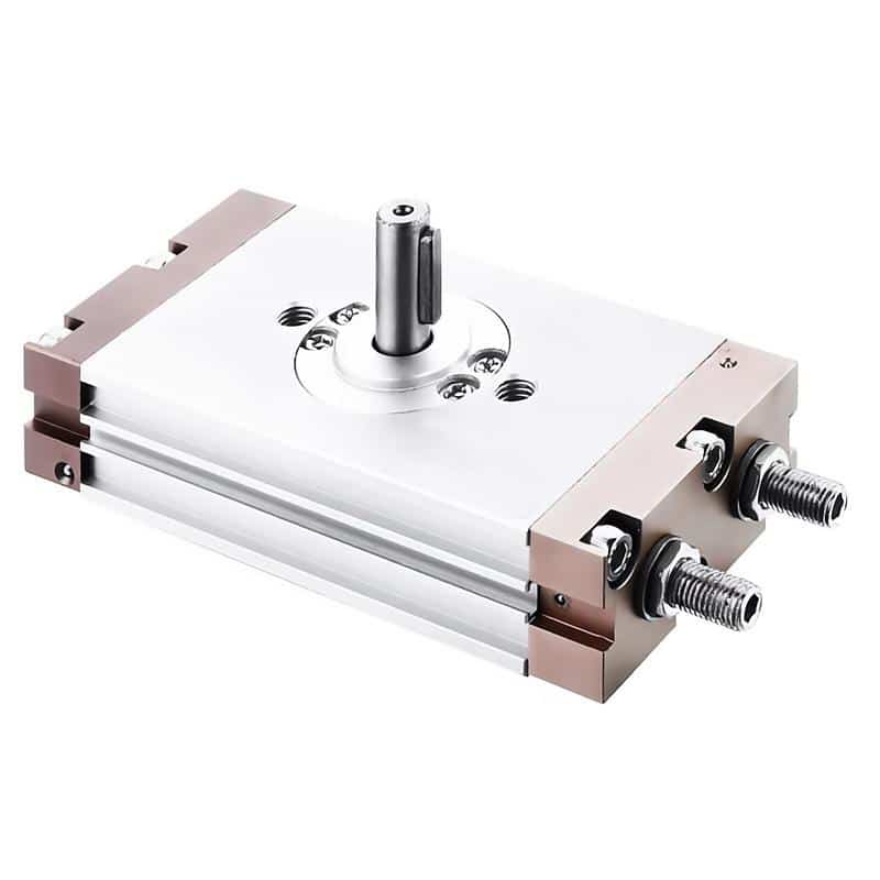
In a rack-and-pinion actuator, piston seals contain the pressure, racks convert linear piston motion, the pinion converts rack travel into shaft rotation, and bearings support the output. Wear evidence can therefore appear on piston seals, rack teeth, pinion teeth, shaft bearings, keys, couplings, cushions, and adjustment hardware.
In a vane actuator, pressure acts on one or more vanes inside a chamber. The important internal surfaces are the vane seals, vane edges, chamber wall, shaft seals, bearings or bushings, and the mechanical stop or adjustment system. A scored chamber or damaged vane sealing edge can create internal bypass without an obvious external leak.
| Wear point | Rack-and-pinion | Vane type | External causes |
|---|---|---|---|
| Pressure seals | Piston bypass, unequal motion | Vane/end-seal bypass | Dirty air, heat, incompatible fluid |
| Torque transfer | Polished or chipped teeth | Vane or chamber scoring | Shock, overload, alignment |
| Output support | Bearing play, seal wear | Bushing/bearing or shaft-seal wear | Overhung or thrust load |
| Stops/cushions | Loose adjuster, bumper debris | Stop marks and rebound | Excess speed or energy |
| Position interface | Key fretting, gear clearance | Shaft/coupling movement | Loose frame, stop, or sensor |
The mechanism comparison matters during inspection. A technician looking for worn gear teeth inside a vane unit is following the wrong failure tree. The same is true when a double-rack design is judged by a single-rack backlash assumption. Review the rack-and-pinion versus vane selection guide if the mechanism itself may be wrong for the duty.
How Does Seal Leakage Cause Rotary Actuator Failure?
A seal problem can appear as an external leak, declining torque, unstable travel time, or a shaft that will not hold. Parker specifies a 5 µm or finer filter for its PRN/PRO vane actuators and requires a leak test after maintenance, tying air cleanliness and verification directly to seal reliability (Parker PRN/PRO manual, accessed July 17, 2026).
First separate external leakage from internal bypass. External leakage is air escaping to atmosphere at a fitting, port thread, body joint, adjustment screw, or shaft seal. Internal bypass is air crossing a pressure boundary inside the actuator, often appearing as low torque, creeping, slow motion, or exhaust flow from the opposite chamber.
Use this sequence while following the machine’s approved energy-control and test procedure:
- Record supply pressure, pressure at both actuator ports during motion, rotation time, load, direction, and temperature before changing anything.
- Inspect tubing insertion, fittings, port threads, body joints, adjustment hardware, and the shaft-seal area.
- Apply an approved leak-detection fluid only to accessible external joints. Do not confuse bubbles at a downstream exhaust with a leak at the actuator body.
- Isolate the valve and actuator branches as the circuit permits. A leaking valve spool can imitate actuator bypass.
- Compare both rotation directions. Direction-specific loss can narrow the fault to one chamber, one cushion path, or one load condition.
- After any repair, repeat the functional and leak tests under the same recorded conditions.
Do not apply universal seal-life numbers. SMC specifies 0 to 60°C with no freezing for the CRQ2 family, but temperature, air chemistry, lubrication policy, cycle profile, pressure, shaft condition, and seal material all remain model- and application-dependent (SMC CRQ2 catalog, accessed July 17, 2026).
Seal replacement also needs a shaft inspection. A new lip seal running over a scored, corroded, or eccentric shaft may leak again. Record the seal orientation, lubricant condition, wear track, debris location, and mating-surface condition before cleaning the parts.
In our experience, the most useful teardown evidence is often lost in the first five minutes. Photograph deposits, polished contact zones, torn seal edges, tooth marks, and lubricant distribution before washing components. Those patterns can distinguish contamination, misalignment, repeated impact, and a simple age-related seal change.
Why Do Shaft Loads and Misalignment Damage Bearings and Gears?
Shaft loading limits are model-specific, not a universal light-duty rule. SMC’s CRQ2X table ranges from 14.7 to 98 N allowable radial load across sizes 10 to 40 and still recommends avoiding direct shaft loads where possible (SMC CRQ2X/MSQX catalog, accessed July 17, 2026).
An overhung load creates bending moment at the actuator shaft:
Here, is the bending moment in N·m, is the radial force in N, and is the perpendicular distance in metres from the supporting bearing or catalog reference point to the load line. Doubling the offset doubles the moment even when the carried mass does not change.
The catalog’s allowable radial force is not permission to ignore moment arm, thrust, dynamic load, or shock. Use the exact model’s drawing and load diagram. A compact rotary actuator may need an external bearing, thrust bearing, flexible coupling, or guided load so the actuator transmits torque without becoming the machine’s structural bearing.
Look for these load-related wear signatures:
- A shaft seal worn more heavily on one side suggests eccentric motion or lateral loading.
- Uneven gear-tooth contact suggests shaft deflection, housing distortion, or alignment error.
- Fretting at the key, coupling, or mounting face points to micro-movement under reversing torque.
- Repeated bearing play after rebuild suggests the external load path was never corrected.
- A warm bearing with no corresponding air leak suggests friction or preload, but temperature alone does not identify the cause.
Rigidly coupling two misaligned shafts forces the bearings to accommodate an offset or angular error. The SMC CRQ2 maintenance manual recommends alignment and a flexible joint when the actuator axis is extended; it also recommends avoiding direct operating loads on the shaft (SMC CRQ2 maintenance manual, accessed July 17, 2026).
The same load-path lesson applies to linear side loading: guide the machine load through a suitable bearing structure instead of asking the actuator’s internal support to absorb an undefined moment. The geometry and catalog reference points differ, so the exact rotary-actuator load diagram still controls the check.
How Does Excess Kinetic Energy Damage Stops, Cushions, and Racks?
Stopping energy can destroy an actuator even when its steady torque appears adequate. SMC lists allowable kinetic energy from 0.00025 J for CRQ2 size 10 with a rubber bumper to 0.4 J for size 40 with an air cushion, and warns that exceeding the model limit can damage internal parts (SMC CRQ2 catalog, accessed July 17, 2026).
The rotating load’s kinetic energy is:
Here, is rotational kinetic energy in joules, is total rotational inertia in kg·m², and is angular speed in rad/s. Because speed is squared, doubling angular speed multiplies kinetic energy by four when inertia remains unchanged.
End-of-travel damage often leaves better evidence than a pressure reading. Inspect adjustment bolts, locknuts, bumper fragments, cushion spears, needle settings, shock absorbers, stop faces, rack-tooth ends, keys, and mounting fasteners. Rebound, a new metallic knock, or a final angle that changes with speed all point toward the stopping system.
Do not close a cushion needle to hide impact without checking rotation time and energy. A misadjusted cushion can slow the final part of travel excessively, raise backpressure, and make the machine miss its timing. Conversely, an open or ineffective cushion can transfer impact into teeth, bearings, stops, and the frame.
Use the rotary actuator torque calculation guide to rebuild the load ledger. For a quick independent check, the Pneumatic Rotary Actuator Torque Calculator estimates load, friction, and acceleration demand. Torque selection and stopping-energy verification remain separate checks.
A repeated cushion failure is usually a system clue. Replacing only the damaged cushion restores the sacrificial part but not necessarily the cause. Recalculate inertia, measure actual rotation time, inspect the external stop, and verify that flow controls have not been opened to recover cycle time lost elsewhere.
Reading Backlash, Angle Error, and Rough Motion
Backlash is mechanism-dependent, so a loose final angle is not automatic proof of worn bearings. SMC states that single-rack CRA1 actuators generate output-shaft backlash, whereas double-piston CRQ and MSQ designs suppress it at the output shaft; stop behavior and holding torque still require model-specific interpretation (SMC rotary actuator FAQ, accessed July 17, 2026).
Backlash is lost angular motion after direction reversal. Measure angle from both approach directions. If the final position changes mainly after reversal, inspect gear clearance, key and coupling movement, stop contact, and linkage play. If it varies from the same approach direction, examine moving pressure, friction, cushion response, sensor mounting, and stop compliance.
Rough motion needs a different test. With the actuator isolated, residual energy controlled, and the load safely supported, compare shaft feel with and without the external load as the manufacturer permits. Binding only when coupled points outward to alignment or the machine bearing. Roughness that remains in the isolated actuator points inward to bearings, gears, vanes, contamination, or damaged seals.
| Test result | Most useful interpretation | Next check |
|---|---|---|
| Free play changes with approach direction | Backlash or external linkage clearance | Key, coupling, gear design, stop contact |
| Final angle changes with rotation speed | Cushion, rebound, stop compliance, sensor timing | Rotation time, cushion setting, stop marks |
| Roughness disappears when uncoupled | External misalignment or load-bearing fault | Coupling alignment, guided load, machine bearing |
| Roughness remains when uncoupled | Internal support or torque-transfer wear | Bearing, rack/pinion, vane, chamber, debris |
| Error appears only under load | Torque deficit, pressure loss, internal bypass, structural deflection | Moving pressure, load torque, leakage, frame stiffness |
Check loose adjustment hardware before assuming internal wear. SMC notes that CRQ2 angle-adjustment locknuts may loosen as operation count increases under some environments and conditions, requiring readjustment if motion is affected (SMC CRQ2 catalog, accessed July 17, 2026).
How Should Contamination and Environment Be Checked?
ISO 8573-1 classifies three compressed-air contaminant groups: particles, water, and oil. It does not prescribe one filter for every actuator; Parker separately specifies 5 µm or finer filtration for its PRN/PRO range, showing why air treatment must follow both system purity targets and the model manual (ISO 8573-1, Parker PRN/PRO manual, accessed July 17, 2026).
Inspect the contamination path, not just the failed seal. Record the filter element condition, drain function, downstream tubing, port orientation, exhaust devices, compressor carryover, recent pipe work, cleaning chemicals, washdown exposure, ambient dust, and freezing risk. Debris inside a new actuator can originate upstream or enter during installation.
| Finding | Likely mechanism | Corrective direction |
|---|---|---|
| Hard particles and linear scoring | Abrasive contamination | Identify source, clean circuit, confirm filtration and assembly practice |
| Rust, water droplets, or swollen deposits | Liquid water or corrosive exposure | Review drying, drains, temperature, enclosure, and material compatibility |
| Sticky varnish or sludge | Oil degradation or incompatible lubricant | Review compressor carryover, lubricant policy, and manufacturer guidance |
| Dry polished seal track | Friction, insufficient approved lubrication, misalignment | Verify non-lube/lube specification and shaft condition |
| Damage concentrated at one port or direction | Ingress path, directional load, or chamber-specific fault | Trace port, valve, exhaust, load, and cushion branch |
Parker warns against air containing corrosive gases, chemicals, or salt for the PRN/PRO range, recommends a dryer where drainage is high, and calls for periodic filter draining. SMC lists 0 to 60°C with no freezing for the standard CRQ2 catalog. These are product instructions, not universal environmental limits.
Use the ISO 8573-1 air-quality guide to specify a purity class, and the FRL maintenance guide to check local filtration, regulation, drainage, and lubrication policy. Do not add lubricant to a non-lube actuator unless its manufacturer permits it.
How Do You Diagnose a Failing Rotary Actuator Safely?
Safe diagnosis begins with energy control, not a leak test. OSHA 29 CFR 1910.147 covers pneumatic energy and requires stored or residual energy to be relieved, restrained, or otherwise made safe before servicing; ISO 4414 likewise addresses maintenance and reliable operation of pneumatic systems (OSHA, ISO 4414, accessed July 17, 2026).
Use the site’s approved lockout/tagout procedure and the actuator manual. A closed-center valve can trap pressure between the valve and actuator. Gravity, springs, counterweights, raised tooling, and rotating inertia can also store energy after the supply valve is closed.
Step 1: Define the symptom and acceptance limit
Write the actual failure statement: for example, “rotation time increased from the recorded baseline under the same load,” “external leakage is present at the shaft,” or “final angle differs by approach direction.” Avoid vague work orders such as “actuator weak.”
Step 2: Record the operating condition
Capture the full model number, pressure at the actuator during motion, rotation time, angle, direction, cycle rate, load, centre-of-gravity radius, orientation, valve state, flow-control setting, temperature, recent maintenance, and fault history. Photograph couplings, stops, mounting, tubing, and adjusters before disturbing them.
Step 3: Separate the air circuit from the mechanical load
Check supply and exhaust restrictions, pressure variation, valve leakage, tubing damage, and flow-control settings. Then compare loaded and unloaded behaviour only where the machine design and manufacturer procedure allow it. The pressure fluctuation diagnostic guide helps when moving pressure changes with other machine demand.
Step 4: Inspect external wear points
Check mounting fasteners, adjustment locknuts, stop faces, shock absorbers, shaft seals, keys, couplings, external bearings, sensor brackets, and cable strain. Measure shaft play using the model’s specified reference point and method. Do not substitute a generic vibration threshold from large rotating machinery.
Step 5: Authorize teardown only when it can answer the fault
Before disassembly, confirm that a service kit, drawing, cleanliness process, measurement tools, torque values, and qualified personnel are available. Preserve wear evidence. If the manufacturer restricts disassembly or requires factory service, follow that instruction.
Step 6: Verify the repair as a controlled test
Clear tools and personnel, restore energy under the approved procedure, and complete functional and leak tests. Compare rotation time, pressure, angle, sound, temperature, and leakage with the pre-repair baseline. A repair is not proven by one successful cycle.
The complete pneumatic actuator maintenance checklist covers the broader maintenance loop. This diagnostic sequence stays focused on rotary wear and failure localization.
Rotary Actuator Failure: Repair, Rebuild, or Replace?
A rebuild decision should follow evidence and parts availability, not a fixed age. Parker’s XR service catalog separates bearings, seals, pinion shaft, rack-and-piston assembly, cushion parts, and hardware, and asks for the model and serial number when ordering spares (Parker XR service catalog, accessed July 17, 2026).
Repair an external interface when the actuator itself passes the baseline test and the fault is limited to accessible tubing, fittings, mounting, coupling, stop, sensor, or approved adjustment hardware. Verify that correcting the interface removes the symptom under the original load.
Rebuild the actuator when wear is confined to supported service parts, the housing and shaft remain within manufacturer limits, the root cause has been corrected, and qualified service can restore cleanliness, lubrication, fastener torque, timing, and test conditions. A seal kit is not a cure for chipped teeth, a scored chamber, a bent shaft, or an overloaded bearing seat.
Replace the actuator when structural or precision-critical surfaces are damaged, parts are unavailable, repair is not authorized, the model is unsuitable for the load or environment, or the total verified repair scope approaches a replacement with lower technical risk. Also consider redesign when the same wear pattern returns after a correct rebuild.
Use a disposition record that purchasing and maintenance can both understand:
| Decision input | Record required |
|---|---|
| Identification | Manufacturer, complete model, serial/date code, rotation, shaft, cushion, switch options |
| Failure evidence | Symptom, measurements, photos, wear pattern, affected direction, debris condition |
| Application | Load, inertia, offset, orientation, pressure, rotation time, cycle profile, environment |
| Parts and capability | Approved kit, manual, tools, tolerances, technician qualification, test fixture |
| Root-cause correction | Load support, alignment, air quality, stop energy, settings, guarding, procedure |
| Verification | Leak result, pressure, time, angle, play, sound, temperature, repeated-cycle result |
For a replacement review, send the complete model number, shaft and mounting drawings, load geometry, lowest moving pressure, rotation angle and time, cycle profile, stop method, environmental conditions, photos, and failure evidence through the technical contact page. That package is more useful than the phrase “same size rotary actuator.”
Rotary Actuator Failure FAQs
The SMC CRQ2 catalog spans five sizes, three nominal rotation choices, and several cushion arrangements, which is why universal wear limits are unreliable. These answers provide decision rules, but shaft load, energy, pressure, temperature, service parts, and inspection methods must still come from the exact model documentation (SMC CRQ2 catalog, accessed July 17, 2026).
What is the first sign of rotary actuator seal failure?
There is no single first sign. External bubbles or sound point toward atmospheric leakage, while declining torque, slower travel, creeping, or exhaust flow from the opposite chamber can indicate internal bypass. Record pressure and time, isolate the valve branch, and localize leakage before ordering a seal kit.
Does shaft play always mean the actuator bearings are worn?
No. Measured play can come from the actuator bearing, key, coupling, external linkage, machine bearing, stop, or gear design. Compare movement at defined points, approach from both directions, unload the external mechanism safely, and use the exact model’s allowable load and backlash information before condemning internal bearings.
Can increasing air pressure compensate for a worn rotary actuator?
Higher pressure may temporarily increase available torque, but it does not repair leakage, damaged bearings, misalignment, worn teeth, chamber scoring, or excessive stopping energy. Raising pressure can also increase impact and stress. Measure pressure during motion and correct the root cause within the actuator’s rated pressure range.
How often should a pneumatic rotary actuator be rebuilt?
Use the manufacturer’s interval or condition criteria when provided, then adjust the maintenance plan using cycle count, load, rotation time, leakage trend, environment, air quality, and inspection results. A universal annual rebuild can waste serviceable parts or miss a high-duty actuator that is already outside its limits.
Why does a rebuilt actuator fail again quickly?
Repeat failure usually means the root cause remained outside the replaced parts. Check shaft loading, alignment, kinetic energy, cushion or stop settings, contamination source, pressure variation, service technique, mating-surface damage, and model suitability. Compare the new wear pattern with the previous record before rebuilding the same assembly again.
Sources
Nine primary references support the diagnosis method: four SMC resources, two Parker manuals, two current safety and air-quality standards, and OSHA hazardous-energy guidance. Manufacturer values are quoted only for the named product family because allowable load, kinetic energy, filtration, temperature, backlash, and service instructions vary by mechanism and model.
-
SMC CRQ2 Compact Rotary Actuator catalog. Specifications, rotation time, allowable kinetic energy, temperature, and adjustment guidance. Retrieved July 17, 2026.
-
SMC CRQ2 instructions and maintenance manual. Shaft loading, alignment, coupling, environment, residual-pressure, and restart precautions. Retrieved July 17, 2026.
-
SMC CRQ2X/MSQX Low-Speed Rotary Actuator catalog. Allowable radial, thrust, and moment loads. Retrieved July 17, 2026.
-
SMC Rotary Actuator FAQ: rack-and-pinion backlash. Single-rack and double-piston behaviour. Retrieved July 17, 2026.
-
Parker XR Series Rotary Actuator service catalog. Service parts and internal wear-point identification. Retrieved July 17, 2026.
-
Parker PRN/PRO Pneumatic Vane Rotary Actuator manual. Air quality, environment, maintenance, residual pressure, and post-service testing. Retrieved July 17, 2026.
-
ISO 4414:2010. Pneumatic-system safety, reliable operation, and maintenance scope; confirmed current in 2021. Retrieved July 17, 2026.
-
ISO 8573-1:2010. Compressed-air purity classes for particles, water, and oil. Retrieved July 17, 2026.
-
OSHA Control of Hazardous Energy. Pneumatic energy isolation and stored-energy control during servicing. Retrieved July 17, 2026.
-
SMC Corporation video: MSQ Series Rotary Table. Limited-angle rotary-table operation. Retrieved July 17, 2026.