

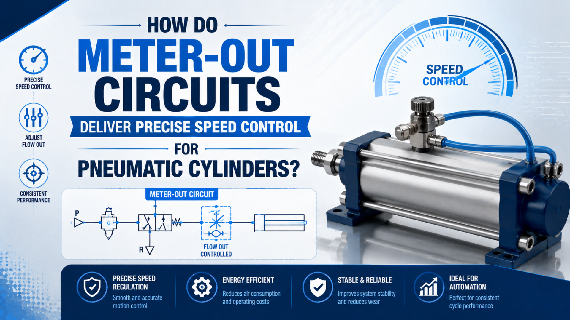
Meter-out circuits control pneumatic cylinder speed by allowing supply air to enter the driving chamber freely while a one-way flow control restricts air leaving the opposite chamber. The controlled exhaust creates back pressure, which resists sudden acceleration and makes motion easier to tune under changing loads. However, it does not turn a pneumatic cylinder into a positioning servo.
In other words, repeatable travel still requires adequate force margin, correct valve orientation, and a known exhaust path. A clogged silencer, tight cushion, or nearly closed needle can add enough back pressure to stall the stroke.
Key Takeaways
- SMC relates cylinder speed and flow with when inlet pressure remains constant.
- A meter-out valve stabilizes motion by restricting exhaust, but that back pressure also subtracts from net cylinder force.
- Mount one-way controls close to both cylinder ports, tune each direction separately, and verify the first stroke after repressurization.
How Does a Meter-Out Circuit Control Cylinder Speed?
SMC explains that cylinder output force depends on pressure while speed depends on airflow. Its imperial relationship is , where is piston speed in inches per second, is airflow in SCFM, and is piston area in square inches, assuming constant inlet pressure.
Meter-out flow control is an arrangement in which a one-way valve passes relatively free flow toward the cylinder while its needle restricts flow leaving the chamber. A double-acting cylinder normally needs one control at each port because its cap-end and rod-end strokes use different exhaust paths and areas.
At the chamber level, the geometric flow needed to sustain a target piston speed is:
Here, is volume flow at chamber conditions, is piston area for extension or annular area for retraction, and is piston velocity. The meter-out restriction determines how quickly that displaced chamber volume can escape. Therefore, closing the needle reduces exhaust flow and speed; opening it increases both until another part of the path becomes the bottleneck.
Importantly, this arrangement controls velocity, not geometric position. End sensors can confirm that a stroke finished, but a manually adjusted restriction cannot by itself hold intermediate position to a universal tolerance. Applications needing commanded positions, multi-stage speed profiles, or load compensation should be evaluated as proportional or servo-pneumatic systems.
The useful control variable isn’t the needle’s turn count alone. It is the pressure-flow operating point created by the cylinder chamber, load, valve opening, tube, directional valve, and muffler. The same setting can produce a different speed after any of those conditions changes.
Why Does Exhaust Back Pressure Stabilize Motion?
SMC identifies exhaust-side control as common practice because back pressure helps regulate cylinder speed. The restriction prevents the exhausted chamber from collapsing immediately, so a load that starts moving faster meets greater opposing pressure. That resistance can damp acceleration, but it cannot make speed independent of load or supply conditions.
The force balance makes the tradeoff visible:
is the driving chamber force. is the opposing force caused by exhaust-side pressure. External load and friction consume the remaining force. If the needle is closed too far, the cylinder may slow, pause near breakaway, or stall before the end sensor.
Exhaust back pressure is the chamber pressure opposing the driving force during a meter-out stroke. In addition, it changes with seal friction, load angle, tube volume, and cushion entry. Therefore, a setting proven with an empty horizontal slide may fail after adding the payload or rotating the axis vertically.
For instance, the separate guide to back pressure in pneumatic systems covers system-wide causes. In a meter-out circuit, some back pressure is intentional; excessive or variable back pressure is the fault.
When Is Meter-Out the Right Choice?
AutomationDirect’s cylinder guidance says flow controls are commonly used to meter air leaving a cylinder, with separate controls for extension and retraction. Meter-out is a strong starting point for double-acting cylinders, especially when gravity, inertia, or another force can assist motion.
For example, use this boundary as an initial engineering screen:
| Motion condition | Meter-out assessment | What must still be checked |
|---|---|---|
| Horizontal load with changing friction | Usually appropriate | Breakaway behavior, guide alignment, force margin |
| Vertical or load-assisted motion | Usually preferred | Load holding, safe stop, restart behavior, gravity risk |
| High inertia near end of stroke | Useful for approach speed | Cushion or shock-absorber capacity |
| Extremely low speed | May expose stick-slip | Low-friction cylinder, guides, seals, proportional control |
| Clean, predictable resistive load | Meter-in may be possible | Runaway risk and full-load tests |
| Quick-exhaust circuit | Requires circuit review | Local exhaust path may bypass ordinary meter-out control |
For the complete method-selection decision, see meter-in versus meter-out flow control. The short rule is that meter-out gives a moving load an exhaust-side restraint. In contrast, meter-in limits filling flow but may not restrain a load that pulls the piston faster than the inlet restriction supplies air.
That said, meter-out is not a load-holding or safety function. On a vertical axis, loss of supply, hose failure, valve leakage, or maintenance isolation can still release motion. Use a risk-assessed circuit and suitable mechanical or pneumatic holding measures where unintended movement can harm people or equipment.
How Much Exhaust Flow Does the Cylinder Need?
ISO 6358-1 defines steady-state methods for characterizing the flow of compressible-fluid components. That matters because a thread size or a single unrestricted flow number does not describe a meter-out valve across every inlet pressure, outlet pressure, or needle position. Use manufacturer curves or ISO 6358 data for final selection.
Specifically, start with the cylinder geometry. For a bore diameter , rod diameter , and stroke :
The swept volume is . Cap-end volume uses ; rod-end volume uses . Because those areas differ, equal extension and retraction times usually require different flow settings.
For a first-pass conversion from chamber volume to normalized free-air demand, use absolute pressure:
is normalized flow, is estimated absolute chamber pressure, and is the chosen reference absolute pressure. Record the reference conditions because catalog values labeled SCFM, ANR, or NL/min may not use identical temperature and pressure bases.
Accordingly, this is a pre-selection estimate. During exhaust, chamber pressure changes, flow can become choked, and valve conductance varies with adjustment. ISO 6358-3 covers system flow characteristics, including subsonic and choked behavior. Final selection still needs the cylinder port, fitting, control, tubing, directional valve, and silencer.
Alternatively, if available flow is already known, the Cylinder Speed Calculator provides the inverse check. Neither tool guarantees the finished speed; both establish a sensible starting range for component selection and commissioning.
Meter-Out Installation and Adjustment
Parker’s flow-control instructions state that a meter-out valve’s full-flow arrow points toward the cylinder. Parker also instructs users to depressurize before service and to secure the selected setting. Verify the symbol or arrow for the exact part instead of judging by body shape.
In particular, install and commission the circuit in this order:
-
Isolate and dissipate pneumatic energy according to the machine procedure. Support suspended loads independently.
-
Confirm that each one-way control passes free flow into its cylinder port and meters flow out of that port.
-
Mount the controls at the cylinder ports where practical. If they must be inline, keep the controlled volume short and use the approved tube size.
-
Inspect the directional valve’s exhaust ports and silencers. Both are downstream restrictions in the meter-out path.
-
Begin with a conservative low-speed setting specified by the valve maker. Never force a needle against its seat.
-
Repressurize gradually, keep people outside the motion envelope, and jog one direction under controlled conditions.
-
Open the exhaust control in small increments until the loaded mid-stroke speed meets the target.
-
Tune the opposite direction independently, then adjust cylinder cushioning for the final part of each stroke.
-
Run repeated cycles at the lowest expected supply pressure and highest approved load.
-
Lock the setting and record the part number, direction, turns from a defined reference, pressure, load, and measured times.
Parker’s catalog describes right-angle meter-out controls intended for direct cylinder-port mounting, with free reverse flow and adjusted exhaust flow. As a result, port mounting reduces the compressible volume between piston and restriction. It also makes the relevant control easier to identify during service.
Tune the hazard, not merely the faster stroke. If gravity assists retraction, establish safe retract behavior before chasing extension cycle time. The two directions can have different loads, areas, risks, and acceptance limits, so equal needle positions are not a meaningful goal.
What Causes Stalling, Creep, or an Uncontrolled First Stroke?
Parker warns in its P33 soft-start instructions that meter-out controls may not regulate adequately while a depressurized system is refilling. If there is not yet trapped air on the exhaust side, the first commanded movement can run faster than later cycles. Therefore, startup must be tested as its own condition.
| Symptom | Meter-out-specific cause | First check | Corrective direction |
|---|---|---|---|
| Cylinder stalls mid-stroke | Excess back pressure or low drive force | Measure both port pressures | Open cautiously; correct load, pressure, or bore |
| Motion hesitates, then jumps | Seal or guide stiction | Compare breakaway and running pressure | Correct friction; restore force margin |
| Speed falls over time | Silencer contamination | Inspect the exhaust path | Replace the restricted component |
| Needle has little effect | Reversed control or another bottleneck | Verify arrow; time its adjustment range | Correct orientation or the true restriction |
| Only one direction is stable | Different load or cap/rod area | Trace both controlled paths | Tune directions independently |
| First startup stroke is fast | Exhaust chamber isn’t pressurized | Compare first and later cycles | Review soft start, valve state, and sequence |
| Stroke slows near the end | Cushion is too restrictive | Compare mid- and end-stroke speed | Tune cushioning after meter-out flow |
| Slow with needle open | Valve, tube, fitting, or muffler limits flow | Measure dynamic and exhaust pressure | Resize the dominant restriction |
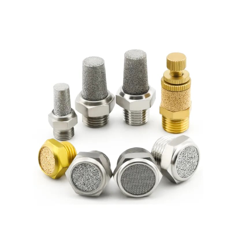
Notably, a silencer is part of the motion-control path. For example, a contaminated element raises pressure downstream of the directional valve, reduces the useful needle range, and alters both stroke times. The pneumatic muffler guide covers selection and maintenance without treating removal as a permanent fix.
In contrast, faults such as dynamic supply collapse, undersized tubing, guide friction, or sensor timing affect every speed-control method. Use the broader actuator flow-control troubleshooting procedure. A meter-out adjustment cannot restore pressure or flow that never reaches the circuit.
How Do Meter-Out Control and Cushioning Interact?
Festo’s cushioning guidance explains that cushioning selection depends on moving mass, speed, acceleration and deceleration, pressure, and cylinder resistance. The meter-out valve controls most of the travel; the cylinder cushion manages deceleration near the end position.
Consequently, impact energy rises with the square of speed according to . Doubling piston speed produces four times the kinetic energy before drive-force work is considered. A faster needle setting can therefore move the stopping problem to the last few millimeters of stroke.
Therefore, use this tuning sequence:
- Establish a safe mid-stroke speed with the external meter-out control.
- Adjust the cushion so deceleration begins near the end without a long pause.
- Confirm that the end sensor switches reliably and the piston doesn’t rebound.
- Repeat at maximum approved load and minimum expected supply pressure.
Don’t use a nearly closed cushion as a substitute for whole-stroke speed control. Conversely, don’t close the meter-out valve until the entire stroke crawls just to solve an end impact. If the moving energy exceeds the cylinder cushion rating, select a larger cylinder cushion, external shock absorber, or lower approach speed. The pneumatic cylinder cushioning guide covers that calculation in detail.
Meter-Out Circuit FAQs: What Should Engineers Check?
These answers define the practical limits of a manual meter-out circuit. They distinguish velocity control from positioning, explain why added back pressure can consume force, and identify startup and low-speed conditions that require more than a needle adjustment.
Does meter-out control improve cylinder positioning accuracy?
It can make end-to-end stroke time more repeatable by damping acceleration, but it does not create closed-loop positioning. A manual flow control cannot guarantee a universal intermediate-position tolerance. Use end sensors for completed strokes and evaluate proportional or servo-pneumatic control when the process requires commanded positions or active load compensation.
Can meter-out control reduce cylinder force?
Yes. Restricting exhaust raises pressure in the non-driving chamber, and that opposing pressure subtracts from the driving chamber force. If a cylinder slows or stalls after adjustment, measure both port pressures during motion and review load, friction, supply pressure, bore size, valve capacity, and the remaining exhaust path.
Should both cylinder ports have flow controls?
A double-acting cylinder normally uses one one-way flow control at each port so extension and retraction can be adjusted independently. Each valve should allow free flow into its chamber and meter flow out. The two settings need not match because piston areas, loads, gravity effects, and target times can differ by direction.
Why does the first stroke run too fast after repressurization?
The exhaust-side chamber may not yet contain enough air for the meter-out restriction to generate normal back pressure. Parker specifically warns about this refill condition. Review the soft-start arrangement, directional-valve state, pressure restoration sequence, and control logic, then validate the first stroke as part of safe machine startup.
Can a standard cylinder run smoothly at very low speed?
Not always. Seal friction and guide friction can produce stick-slip when net force is small, even with careful exhaust metering. SMC offers dedicated low-speed and low-friction actuators, which shows that ultra-low-speed motion is a cylinder-design problem as well as a flow-control problem.
Conclusion
A meter-out circuit controls pneumatic cylinder speed by metering displaced air out of the non-driving chamber. The resulting back pressure resists load-driven acceleration and gives the needle useful control authority. That same pressure consumes force, so stable motion depends on a balanced pressure-flow operating point rather than maximum restriction.
Size from cylinder area, target speed, absolute pressure, and published component flow data. Install one-way controls in the correct direction close to both ports, account for the directional valve and silencer, tune cushioning separately, and test with the real load. Most importantly, verify the first stroke after repressurization; it can behave differently from every cycle that follows.
Sources and Technical References
-
SMC: Control Air Flow of Cylinders, cylinder speed-flow relationship, constant-inlet-pressure condition, and exhaust-side flow control. Accessed 2026-07-17.
-
ISO 6358-1:2013, steady-state testing of pneumatic component flow characteristics. Confirmed current in 2022; accessed 2026-07-17.
-
ISO 6358-3:2014, steady-state flow characteristics of pneumatic systems, including subsonic and choked flow. Confirmed current in 2025; accessed 2026-07-17.
-
Parker Hannifin: Flow Controls and Accessories, direct cylinder-port meter-out controls, free reverse flow, and adjusted exhaust-flow data. Accessed 2026-07-17.
-
Parker Hannifin: Flow Control Valve Service Instructions, meter-out arrow direction, locking, and depressurization guidance. Accessed 2026-07-17.
-
Parker Hannifin: P33 Safety Exhaust Valve Instructions, soft-start behavior and first-actuation warning for depressurized meter-out circuits. Accessed 2026-07-17.
-
AutomationDirect: Pneumatic Cylinder FAQ, meter-out placement and separate extension/retraction adjustment. Accessed 2026-07-17.
-
Festo: Cylinder Cushioning, the Three Most Common Methods, pneumatic cushion variables and adjustment. Accessed 2026-07-17.
-
SMC: Low-Speed and Low-Friction Actuators, dedicated designs for stable low-speed operation. Accessed 2026-07-17.