

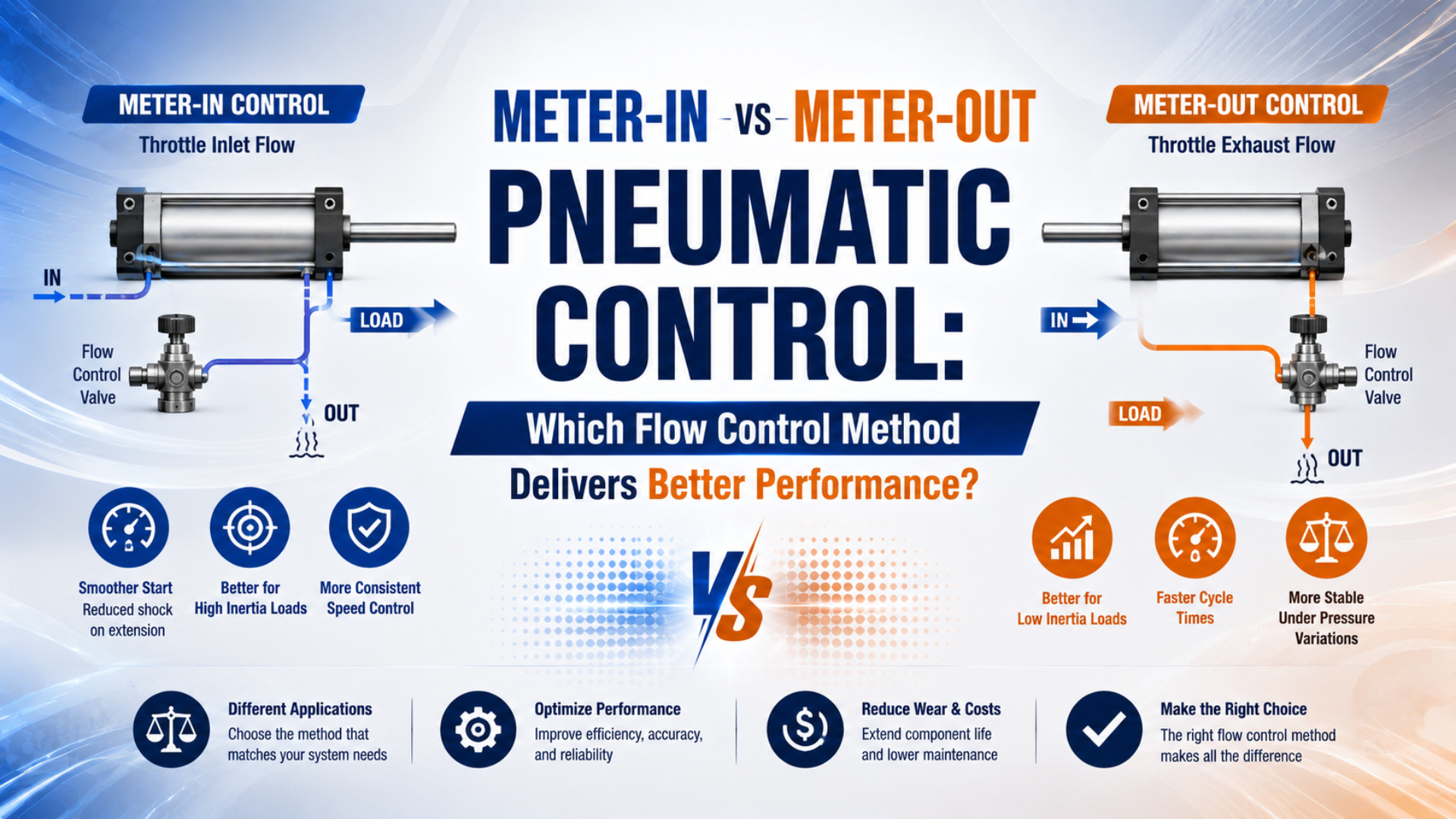
Meter-out delivers steadier speed in most double-acting pneumatic cylinder applications because it restricts exhaust and creates controllable back pressure. Meter-in is appropriate when the load consistently resists motion and the supply-side restriction can govern speed without the piston overrunning it. Choose by load direction and force margin, not by a universal light-versus-heavy weight threshold.
SMC calls exhaust-port flow control the most common industry practice and gives the speed relationship when inlet pressure is held constant (SMC, retrieved 2026-07-22). That relationship is a starting point. Port pressure, tubing, valve capacity, friction, cushions, and the moving load still shape the actual stroke.
Key Takeaways
- Meter-out is the normal first choice for variable, vertical, or load-assisted motion.
- Meter-in can work when the load stays resistive and predictable.
- Exhaust back pressure improves control but subtracts from net cylinder force.
- A speed controller is not a load-holding or anti-drop device.
What Changes When You Meter In or Meter Out?
SMC’s cylinder-speed relation uses a coefficient of 28.8 when speed is in inches per second, flow is in SCFM, and piston area is in square inches (SMC, retrieved 2026-07-22). Meter-in and meter-out change which chamber’s flow and pressure govern that motion.
Meter-in control is a circuit arrangement that restricts air entering the chamber that drives the stroke. A check-valve bypass allows free flow in the reverse direction. The active chamber fills more slowly, so its pressure may remain below supply pressure while the piston is moving.
Meter-out control is a circuit arrangement that allows relatively free inlet flow but restricts air leaving the opposite chamber. The exhaust-side pressure rises above atmosphere and resists acceleration. This pneumatic braking effect is why meter-out usually handles changing friction or assisting loads more consistently.
Festo likewise states that a one-way flow control restricts one direction while allowing full flow in reverse, and that cylinder speed can be regulated by reducing either supply or exhaust flow (Festo, retrieved 2026-07-22).
The important load label is not “light” or “heavy.” It is resistive or assisting. A heavy guided load that consistently resists motion can be predictable. A small vertical load can still overrun the piston when gravity acts in the travel direction.
How Does Meter-Out Back Pressure Change Cylinder Force?
Parker’s cylinder example calculates 4,750 lbf on the cap side, subtracts 1,000 lbf from 25 psi acting on the smaller rod-side area, and obtains 3,750 lbf net extension force (Parker Designing With Cylinders, retrieved 2026-07-22). Meter-out uses that opposing pressure deliberately, so it must appear in the force budget.
For extension of a single-rod double-acting cylinder:
For retraction:
Here, and are the cap- and rod-side gauge pressures at the cylinder ports, is full piston area, is rod area, is friction, and is the external resisting load for the direction being checked. Assign signs consistently if an external load assists motion.
Consider an illustrative extension using a 50 mm bore, 20 mm rod, and meter-out back pressure . The areas are:
Before subtracting friction and the external load:
Without rod-side back pressure, the same cap-side pressure produces about 982 N before friction and load. The meter-out setting therefore stabilizes motion by spending some force margin. If the cylinder stalls after adjustment, don’t immediately open the needle. Measure both port pressures and compare the remaining net force with the real load.
This two-chamber check complements the broader explanation of how pressure differential creates pneumatic force.
When Is Meter-In the Better Choice?
Festo’s one-way flow-control description identifies 1 restricted direction and free reverse flow, with supply-air and exhaust-air control both available (Festo, retrieved 2026-07-22). Meter-in is the better choice when controlled chamber filling governs the stroke and the load cannot accelerate ahead of that filling process.
Good meter-in candidates include horizontal pushers, low-mass fixtures, single-acting cylinders that need controlled pressurization, and motions where the opposite chamber must exhaust with minimal restriction. The payload, guide friction, linkage geometry, and orientation should stay predictable throughout the stroke.
Meter-in deserves consideration when:
- the load always resists the commanded direction;
- gravity does not assist the stroke;
- a sudden friction drop cannot cause an overrun;
- available force remains adequate at the reduced moving pressure;
- rapid free exhaust is a deliberate process requirement.
There are also components that combine both behaviors. SMC’s ASD family places meter-in and meter-out adjustment in one body, which is useful when startup and normal travel need different restrictions (SMC ASD, retrieved 2026-07-22). That product category shows why “one cylinder must use only one method” is too simple.
Meter-in still needs force verification. Restricting supply can hold the active chamber below regulator pressure while the piston is moving. If the motion pauses or stalls, pressure may continue rising, so static and moving force can differ substantially.
Which Method Fits Vertical or Overrunning Loads?
SMC’s ASS safety speed controller uses 2 control phases: meter-in when the circuit has no pressure, then ordinary meter-out after pressurization (SMC ASS, retrieved 2026-07-22). That design addresses two separate risks, sudden movement during startup and unstable speed after the cylinder begins moving.
For a vertical lowering stroke or another assisting load, meter-out is normally the better starting point. The exhaust restriction prevents the piston from moving freely ahead of the controlled airflow. Tune at the lowest expected working pressure and with the heaviest and lightest permitted payloads, because both extremes can expose different problems.
An overrunning load is a load that tends to move the actuator in the commanded direction faster than the controlled air supply would drive it. Gravity, springs, counterweights, and linkage geometry can all create this condition. The load’s direction matters more than its mass alone.
Meter-out does not make a vertical axis safe after air loss. This is an inference supported by SMC offering a separate pilot-check function to add temporary stop or hold capability to a meter-out speed controller (SMC ASP, retrieved 2026-07-22). A risk-assessed machine may require a rod lock, mechanical brake, counterbalance arrangement, pilot-operated check, or another engineered holding measure.
Don’t confuse four functions:
| Function | Typical component or method | What it does not guarantee |
|---|---|---|
| Speed regulation | Meter-in or meter-out flow control | Safe load holding after pressure loss |
| Startup pressurization | Soft-start or staged speed-control device | Controlled emergency stopping |
| Temporary pneumatic stop | Pilot-operated check arrangement | Zero drift under leakage or hose failure |
| Safety-rated holding | Risk-assessed mechanical or safety system | Normal speed adjustment by itself |
For vertical cylinder sizing, combine this control choice with the vertical-up cylinder force and pressure checks.
The best normal-motion setting and the safest power-up behavior may require different flow paths. Treat startup, travel, stopping, and loss of pressure as four states rather than expecting one needle valve to solve all of them.
Circuit Installation: Port Direction and Valve Placement
AutomationDirect states that 2 one-way flow controls let a double-acting cylinder’s extension and retraction speeds be adjusted independently; it also allows valve-exhaust mounting when tubing to the cylinder is less than about 3 ft (AutomationDirect, retrieved 2026-07-22). Direct cylinder-port mounting usually makes the controlled volume and valve orientation easier to verify.
Check the component symbol and arrow, not just the elbow’s physical direction. Manufacturers sell meter-in and meter-out versions that can look almost identical. A one-way flow control valve is a restriction combined with a check bypass: one direction passes through the adjustable needle while reverse flow travels through the check path.
For a conventional double-acting cylinder:
- Identify which chamber is driving the commanded stroke.
- Identify which chamber is exhausting.
- For meter-out, allow free flow into the driving chamber and restrict flow leaving the exhausting chamber.
- Use the second controller to set the opposite stroke independently.
- Mount close to the actuator unless the selected product documentation permits another location.
- Record the valve series, metering direction, needle turns, and locked setting.
Long tubing adds compressible volume between the cylinder and remote restriction. The response can feel springier, and pressure near the valve may not represent pressure at the cylinder port during rapid motion. The pneumatic hose and fitting size guide explains why tube ID and length belong in the same review.
Mufflers also matter. A contaminated or undersized silencer can become an unintended second meter-out restriction. If speed changes after maintenance, check the silencer, valve exhaust, quick couplers, and needle orientation before replacing the cylinder.
A Practical Selection and Commissioning Sequence
SMC relates cylinder speed to flow through and states that port and tubing sizes also affect speed (SMC, retrieved 2026-07-22). Select the metering direction after defining load behavior, but size the airflow path before expecting a needle valve to achieve the target stroke time.
In SMC’s imperial-unit relationship:
Here, is piston speed in inches per second, is flow in SCFM, and is piston area in square inches. SMC specifies that inlet pressure must be held constant. Use manufacturer sizing data or a compressible-flow model when pressure changes materially during the stroke.
Use this commissioning order:
- Confirm bore, rod, stroke, moving mass, orientation, and target time in each direction.
- Classify each stroke as resistive, neutral, or load-assisted.
- Calculate the required flow and check the directional valve, tube, fittings, and exhaust path.
- Verify the one-way flow-control direction before applying pressure.
- Start with the controller mostly closed, then open it gradually.
- Measure stroke time and both cylinder-port pressures under the real payload.
- Confirm net force remains positive throughout motion.
- Test low supply pressure, payload limits, startup, stop, and exhaust conditions.
- Lock and document the final setting.
In our experience, the fastest diagnosis comes from separating two questions: “Is the circuit passing enough flow?” and “Is the restriction on the correct side?” Opening a needle cannot correct an undersized valve, and a larger valve cannot stabilize an overrunning load if the exhaust path is uncontrolled.
For the required-flow calculation, use the cylinder flow requirement guide. For valve capacity, continue with the pneumatic flow-control valve sizing guide.
Common Symptoms and Corrections
CAGI says a well-designed compressed-air system should have no more than 10% pressure drop from compressor discharge to the point of use and recommends air velocity of 20 ft/s or less in distribution piping (CAGI, retrieved 2026-07-22). Excessive upstream loss can imitate a badly adjusted flow controller.
| Symptom | Likely mechanism | First check |
|---|---|---|
| Piston jumps after breaking static friction | Meter-in on a load-assisted stroke | Test meter-out and measure exhaust pressure |
| Cylinder becomes weak as the needle closes | Excess meter-out back pressure | Calculate two-chamber net force |
| Both directions are slow with needles open | Supply, valve, tube, or muffler restriction | Measure pressure at both cylinder ports |
| One direction ignores adjustment | Check-valve orientation is reversed | Verify the product symbol and metering direction |
| Motion changes after silencer replacement | Exhaust restriction changed | Compare muffler flow rating and contamination |
| Cylinder bangs during repressurization | Chamber starts empty or unbalanced | Review staged pressurization and startup control |
| Vertical load drifts after stop | Leakage or no positive holding device | Review pilot check, lock, or mechanical brake |
Speed controls should fine-tune a correctly sized air path. They should not conceal an undersized directional valve or blocked exhaust. If both strokes remain slow, follow the broader compressed-air pressure-drop troubleshooting sequence before changing metering direction.
End-of-stroke impact is a separate energy problem. Flow control sets travel speed, while the cushion or shock absorber manages the remaining kinetic energy near the stop. The pneumatic air-cushioning guide covers that boundary.
Meter-In vs Meter-Out FAQs: What Should Engineers Check?
AutomationDirect recommends 2 one-way flow controls for independent extend and retract adjustment, while SMC’s speed relationship uses the factor 28.8 for SCFM, square inches, and inches per second (AutomationDirect; SMC, retrieved 2026-07-22). These questions separate metering direction from force, safety, and installation.
Is meter-out always the best choice?
No. Meter-out is the usual starting point when the load varies or assists motion because exhaust back pressure resists acceleration. Meter-in can work better when the load remains resistive, rapid exhaust is required, or staged pressurization is the priority. Verify both methods against force margin and startup behavior.
Why can meter-out make a cylinder feel weak?
The exhaust restriction creates pressure in the chamber opposing motion. That pressure acts on the effective piston area and subtracts from driving force. Measure both cylinder-port pressures, calculate the two-chamber net force, and check friction and load before opening the controller or increasing the regulator setting.
Can one cylinder use meter-in in one direction and meter-out in the other?
Yes. Extension and retraction can have different load directions, areas, speeds, and control risks. Select each direction independently and use components whose check and restriction paths match the intended circuit. Some dual speed controllers also combine meter-in and meter-out adjustment in one body.
Does meter-out hold a vertical load after air loss?
No. A standard speed controller regulates flow during normal motion; it is not a positive load-holding device. A vertical safety function may need a pilot-operated check, rod lock, brake, counterbalance arrangement, or other risk-assessed measure. Also plan residual-pressure release and maintenance access.
Which way should the arrow point on a speed controller?
Follow the selected manufacturer’s symbol because arrow conventions and body markings can vary. Identify the restricted direction and the free check-valve direction from the datasheet. For meter-out, the restricted path must carry air leaving the cylinder during the controlled stroke; reverse flow should enter freely.
Sources and technical references
- AutomationDirect Actuator FAQ, accessed 2026-07-22.
- CAGI Technical Brief on Pressure Drop, accessed 2026-07-22.
- Festo One-Way Flow Control Valves, accessed 2026-07-22.
- Parker Designing With Cylinders, accessed 2026-07-22.
- SMC Control Air Flow of Cylinders, accessed 2026-07-22.
- SMC ASS Safety Speed Control Valve, accessed 2026-07-22.
- SMC ASP Speed Controller With Pilot Check, accessed 2026-07-22.