

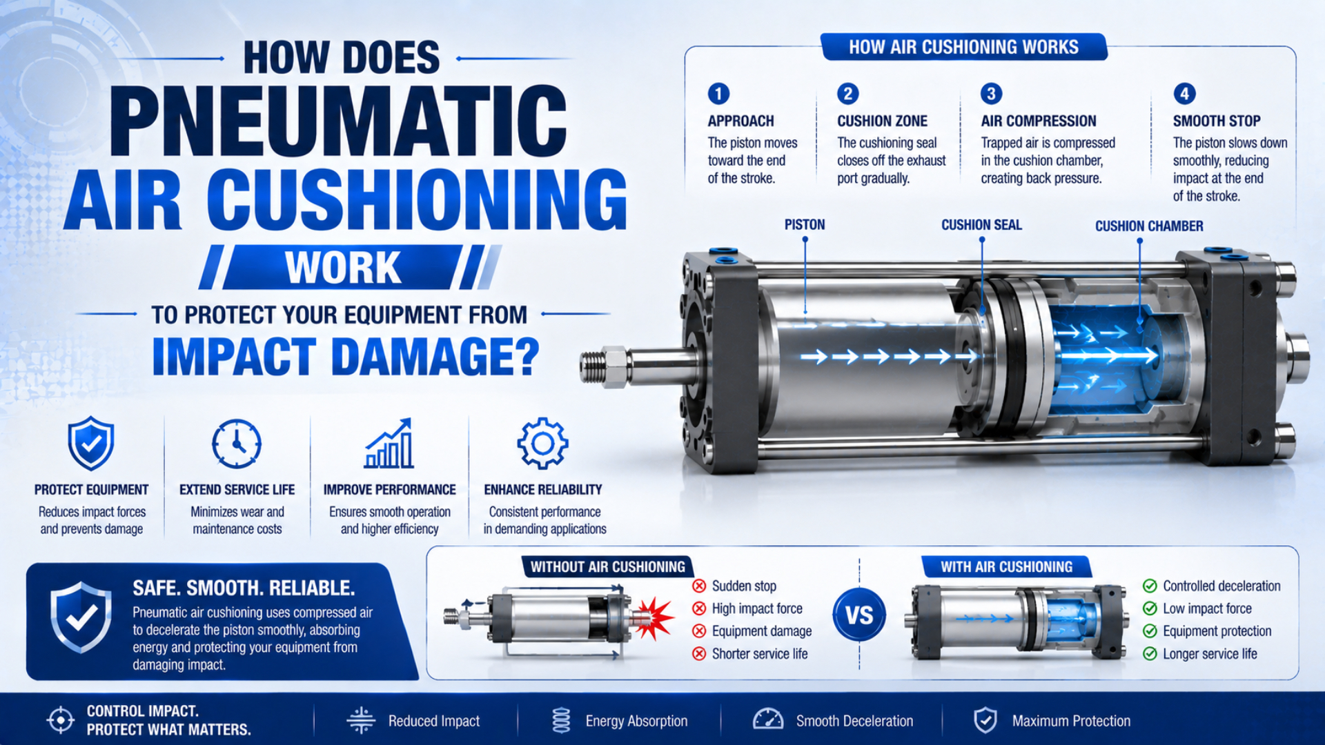
Pneumatic air cushioning is a controlled end-of-stroke deceleration method that protects a machine by restricting exhaust flow during the final part of a cylinder stroke. A cushion sleeve closes the normal exhaust path, air becomes trapped in the end chamber, and controlled bleed flow creates back pressure before the piston reaches the mechanical end. The cushion does not erase impact energy. It manages when and where that energy is dissipated. Protection therefore depends on the real moving mass, speed at cushion entry, continuing cylinder force, usable cushion stroke, adjustment, exhaust condition, and the exact cylinder’s published limits. A smooth-looking stop isn’t enough if the piston still hits the cap with residual energy.
Key Takeaways
- Parker warns that cushion-entry speed is typically about 50% higher than average stroke speed.
- Air cushioning protects the cylinder only when moving energy stays within model-specific limits.
- Tune for full end-position arrival without a metallic hit, rebound, or prolonged crawl.
- Use an external stopping device when the built-in cushion is outside its catalog envelope.
Readers who need the broader cylinder-level topic can use the guide to pneumatic cylinder cushioning, noise, and adjustment. This article concentrates on the damage chain: how the cushion establishes braking pressure, how residual impact reaches the machine, and what evidence verifies protection.
What Actually Happens When Pneumatic Air Cushioning Begins?
Festo divides cylinder end cushioning into 3 broad methods: elastic, pneumatic or servo-pneumatic, and hydraulic damping. In adjustable pneumatic cushioning, a defined air volume is trapped in the end chamber and its outflow is controlled by an adjustment screw (Festo, 2022, accessed 2026).
During most of the stroke, exhaust air leaves through the main port with relatively little restriction. Near the end, a cushion sleeve or boss enters a matching seal or bore in the end cover. That event separates the remaining chamber from the main exhaust path. Air can then leave only through a smaller metering passage. Pressure rises because the piston continues reducing the trapped volume while exhaust flow is restricted. The chamber pressure acts on the piston face opposite the direction of travel, producing a braking force before the piston reaches the cap.
Three physical events must stay in the correct order:
- Free stroke: the main exhaust path supports the required travel speed.
- Cushion engagement: the sleeve closes the main path without damaging the cushion seal or binding in the end cover.
- Controlled bleed: trapped air exits through the metering path while the piston decelerates and still reaches its final position.
What if engagement occurs but the needle passage is too open? Back pressure remains too low and the piston retains excessive speed. If the passage is too restrictive, pressure may rise early enough to cause rebound, a slow final approach, or failure to confirm the end-position sensor within the expected time.
The cushion sleeve is not the brake by itself. It is the switching element that changes the exhaust route. The actual braking force comes from chamber pressure acting on piston area, so a worn seal, damaged sleeve, blocked passage, altered muffler, or changed supply pressure can modify the stop even when the adjustment screw has not moved.
Which Inputs Determine Whether Cushioning Can Protect the Machine?
Parker warns that piston speed at the start of cushioning is typically about 50% higher than average stroke speed and uses that higher value with cushioned mass to select the cylinder. If the permissible chart is exceeded, Parker requires additional shock absorbers (Parker-Origa, accessed 2026).
Average speed equals full stroke divided by stroke time, but it can hide acceleration through the middle of travel. Cushion-entry velocity is the speed immediately before the sleeve closes the main exhaust path. It is the better input for moving-energy screening because kinetic energy rises with the square of velocity.
Kinetic energy at cushion entry is:
is kinetic energy in joules, is the translated mass in kilograms, and is measured or defensibly calculated cushion-entry velocity in metres per second. Include the piston, carriage, tooling, workpiece, brackets, and any other mass moving into the stop. This is a screening equation, not a cylinder capacity rating.
If pneumatic thrust, gravity, a spring, or another force continues driving the mechanism during the cushion stroke, its work must also be considered:
is drive work in joules, is the net force still acting in the direction of travel in newtons, and is usable cushion stroke in metres. Gravity work is positive when gravity drives the load toward the stop and negative when it opposes motion.
A conservative first-pass requirement is:
Compare that result with the exact manufacturer’s cushion chart under the stated pressure, direction, speed, mounting, guide, and adjustment assumptions. Do not transfer an allowable energy value from another bore or series.
Further guidance on velocity measurement and cycle-time tradeoffs appears in the high-speed cylinder air-cushion guide. If the machine has a vertical axis, use the actual direction of gravity rather than treating both stroke directions as identical.
Cushion Energy Must Be Checked Against Model Data
SMC’s MGPK manual publishes separate air-cushion values by bore: one configuration lists 0.7 J at 32 mm and 2.17 J at 50 mm, with effective cushion lengths of 10.5 mm and 11.5 mm respectively (SMC MGPK Manual, accessed 2026). These numbers demonstrate why generic mass, speed, or joule thresholds are unsafe.
A model-level check should record every condition attached to the catalog value:
| Required input | Why it matters | Evidence to retain |
|---|---|---|
| Exact series, bore, and stroke | Cushion geometry and energy limits vary by configuration | Nameplate, order code, current data sheet |
| Moving mass | Determines kinetic energy | Tooling and workpiece mass breakdown |
| Cushion-entry velocity | Energy depends on velocity squared | Measurement method, stroke direction, operating point |
| Net drive force | Pressure or gravity may keep adding energy | Pressure during motion, piston area, orientation |
| Effective cushion stroke | Sets available stopping distance | Model drawing or catalog value |
| Cycle rate | Repeated events can create heat and setting drift | Sustained production cycles per hour |
| Guide and load path | Side load can create damage that cushioning cannot correct | Guide model, offsets, alignment record |
Catalog values are application boundaries, not advertising comparisons. An air cushion rated for a particular energy can still perform poorly if the piston enters too fast, the needle setting is wrong, the exhaust passage is contaminated, or the load applies a side moment that the cylinder was never designed to guide. Treat the energy calculation and the final-stroke observation as two independent gates. A calculation below the catalog value does not prove correct adjustment. A quiet stop does not prove capacity if the machine is running below its worst load, pressure, speed, temperature, or cycle rate during the test.
For machine-level stopping analysis, the end-of-stroke force and energy guide separates internal cushion load, external stop reactions, guide moments, and structural consequences.
How Does Cushion Adjustment Change End-of-Stroke Behavior?
SMC’s current CM2 guidance warns against both extremes: operating with the cushion needle fully closed can damage the cushion seal, while opening it more than 3 turns from fully closed can make the cylinder behave as though it has no cushion (SMC CM2 Catalog, accessed 2026). That limit belongs to the cited series, not every cylinder.
Always follow the selected model’s adjustment procedure and safety instructions. The permitted direction, starting position, turn range, retaining method, tool, and energized-adjustment rules can differ. Don’t copy a setting or rotation count from another cylinder family.
Use behavior to guide the model-approved adjustment:
| End-of-stroke behavior | Likely condition | Check before changing the needle |
|---|---|---|
| Sharp metallic strike | Too little effective damping or excess entry energy | Load, entry speed, pressure, seal bypass, needle opening |
| Piston rebounds | Excess trapped pressure, load elasticity, or late hard contact | Needle restriction, load guidance, external stop position |
| Long crawl into the sensor | Excess restriction or inadequate drive pressure | Needle setting, muffler, valve, tubing, pressure during motion |
| Stop changes after warm-up | Temperature, seal friction, flow, or load has shifted | Sustained-cycle pressure and timing record |
| One direction is smooth and the other bangs | Moving mass, piston area, gravity, or settings differ by direction | Extend and retract inputs separately |
| Adjustment has little effect | Cushion is bypassing or the fault is outside the cushion | Sleeve, seal, needle passage, hard stop, guide alignment |
Set normal cylinder speed before fine-tuning the cushion. A meter-out speed-control arrangement is common because it maintains exhaust back pressure, but the circuit must match the application. A cushion screw cannot compensate for an undersized directional valve, clogged muffler, excessive tube restriction, unstable pressure, or poor guidance.
In our experience, maintenance teams get a more repeatable result when they record three values after every small adjustment: total stroke time, time spent in the final cushion zone, and whether the end-position sensor confirms without rebound. Sound is useful evidence, but timing and position keep the decision from depending on one person’s hearing.
Circuit behavior is covered separately in the meter-out circuit guide, which explains why exhaust-side control and load direction can change pneumatic motion stability.
What Damage Patterns Show Cushioning Is Failing?
SMC’s RLQ precautions publish allowable residual collision energy from 0.15 J for a 32 mm bore to 0.77 J for a 63 mm bore at stated conditions, and warn that excessive residual energy can damage machinery (SMC RLQ Precautions, accessed 2026). Impact evidence should therefore be traced to the exact stop and direction.
Look for a pattern instead of replacing the most visible part:
| Evidence | Possible cushion-related cause | Competing cause to rule out |
|---|---|---|
| Repeated cap-end witness marks | Residual piston energy at the end of cushion travel | Assembly error or foreign material |
| Loose cylinder or guide fasteners | Repeated shock entering the support structure | Side load, poor mounting surface, wrong torque |
| Cracked bracket or fretting around bolts | End-stop reaction exceeds structural load path | Frame flexibility or off-axis hard stop |
| Intermittent end-position signal | Rebound or slow final approach | Sensor position, wiring, magnet orientation |
| Cushion seal damage at one end | Over-restriction, contamination, or sleeve damage | Wrong seal kit or assembly damage |
| Load continues moving after piston stops | Tooling or payload is not controlled by the cylinder cushion | Guide clearance, coupling flexibility, separate load inertia |
A cushion protects the piston and cylinder end only through its internal pressure path. It cannot correct cylinder side loading, stop an independently sliding payload, or absorb a machine-frame collision that occurs before cushion engagement. Map each mark to the physical load path and stroke direction. Before disassembly, record working pressure during motion, stroke time in each direction, cushion-zone time, load and tooling condition, sensor state, rebound, noise character, needle position, muffler condition, and the exact location of impact marks. Photograph witness marks before cleaning or loosening the mounts.
If mounting bolts, rod bearings, or seals show directional wear, review linear-cylinder side-load mitigation instead of assuming the cushion caused every failure.
When Is Built-In Pneumatic Air Cushioning Not Enough?
Parker’s OSP guidance states that additional shock absorbers are required when the published cushioning diagram is exceeded, and its selection uses cushioned mass plus piston speed at cushion entry (Parker-Origa, accessed 2026). The decision is model-specific rather than a universal 50 kg, 2 m/s, or 100 J rule.
Escalate to an external shock absorber, larger actuator, longer controlled stop, reduced approach speed, or revised motion profile when:
- the operating point exceeds a published cushion mass, speed, or energy boundary under the documented pressure and mounting orientation;
- gravity or pneumatic thrust keeps adding work, a separate hard stop controls machine position, or the payload, carriage, or flexible tooling continues moving after the cylinder piston stops;
- sustained cycle rate creates unacceptable temperature, timing drift, or inconsistent damping after warm-up;
- variable loads span conditions that cannot all be controlled within the cylinder’s permitted adjustment envelope;
- the stop must deliver a documented deceleration profile, repeatability target, or structural reaction-force limit.
An external shock absorber also has per-event energy, energy-per-hour, impact-speed, effective-mass, return-time, temperature, alignment, and mounting limits. “External” does not mean unlimited. Use the external shock absorber sizing workflow to select a specific unit. Built-in cushioning may still be useful when an external stop carries the main energy. The two devices must be timed so the external absorber engages as designed while the piston does not slam internally afterward. Verify the complete sequence under the worst credible load and speed.
A Verification Record Protects the Next Maintenance Cycle
AVENTICS publishes different cushion lengths across one CVI family: 11.5 mm for a 32 mm bore and 22 mm for a 125 mm bore, with intermediate sizes using other values (AVENTICS CVI Catalog, accessed 2026). A maintenance record must therefore identify the exact configuration, not merely “ISO cylinder with air cushion.”
Record the cylinder series, bore, stroke, orientation, moving mass, cushion-entry velocity, pressure during motion, cycle rate, cushion setting, speed-control setting, muffler and valve models, final-stroke time, rebound observation, sensor confirmation, temperature after sustained cycling, and applicable catalog limits. Clear release criteria should include no hard internal strike, no visible rebound, full end-position confirmation, stable cycle timing, no new witness marks or loosened hardware, and operation inside every published boundary. Repeat the check after a load, speed, pressure, valve, muffler, guide, or tooling change. That record turns the next failure review into a comparison instead of a fresh guess. It also supplies the data needed for a replacement RFQ when the installed cushion cannot meet the application.
Pneumatic Air Cushioning FAQs
Festo separates end cushioning into 3 methods, while Parker warns that cushion-entry speed can be about 50% above average speed. Together, those facts explain why a cylinder’s cushion type and real approach velocity must be identified before adjustment, energy screening, or replacement (Festo, 2022; Parker, accessed 2026).
How do I know whether air cushioning is protecting the machine?
Confirm that the cylinder reaches its end position without a metallic strike, visible rebound, prolonged final crawl, or timing instability. Then compare moving mass and cushion-entry velocity with the exact catalog limit. A quiet stop alone is insufficient if the machine was tested below its worst production load, speed, pressure, or cycle rate.
Should I close the cushion needle completely before adjustment?
Follow the exact cylinder instructions. SMC’s CM2 guidance warns that fully closed operation can damage its cushion seal, while another SMC series specifies a fully closed starting point followed by gradual reopening. These different procedures prove that adjustment direction, starting position, tool, and permitted turns cannot be generalized across cylinder families.
Can built-in air cushioning replace an external shock absorber?
Only when the installed operating point remains within the selected cylinder’s cushion chart and the cushion controls the complete moving load. Parker requires additional shock absorbers when its permissible values are exceeded. External stopping is also needed when a separate carriage, hard stop, gravity load, or tooling motion bypasses the internal cushion’s load path.
Why does one stroke direction need a different cushion setting?
Extension and retraction can have different piston areas, net drive forces, gravity work, hose movement, and guided-load reactions. The actual cushion-entry velocity may differ as well. Calculate and observe both directions separately, then use each end’s model-approved adjustment procedure instead of copying one needle position to the opposite end.
Can pneumatic cushioning be added to any existing cylinder?
Not automatically. Built-in air cushioning requires compatible internal geometry, including a cushion sleeve or boss, matching seal or bore, trapped-air chamber, and metered exhaust passage. Check whether the manufacturer offers an approved conversion for the exact series. Otherwise choose a cushioned replacement, external absorber, or lower-energy motion profile.
Sources and technical references
- Festo, Cylinder Cushioning: The Three Most Common Methods, pneumatic cushioning mechanism and adjustment inputs; 2022, accessed 2026-07-22.
- Parker-Origa, Pneumatic Linear Drives, cushion-entry speed and mass-based selection; accessed 2026-07-22.
- SMC MGPK Manual, allowable kinetic energy and effective cushion length by configuration; accessed 2026-07-22.
- SMC CM2 Catalog, model-specific cushion needle precautions; accessed 2026-07-22.
- SMC RLQ Precautions, residual collision energy and adjustment warnings; accessed 2026-07-22.
- AVENTICS CVI Catalog, bore-specific cushioning lengths; accessed 2026-07-22.