

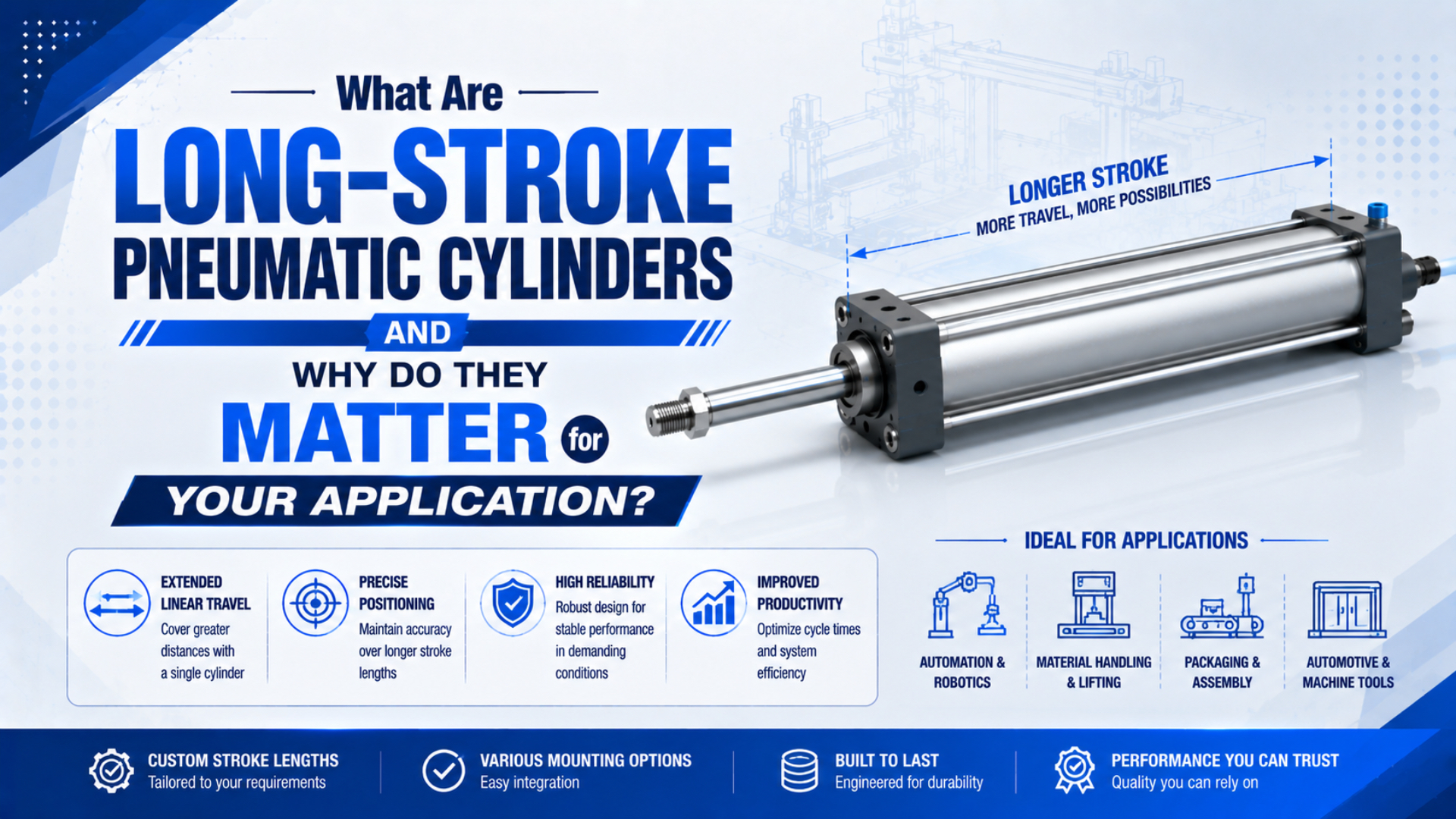
A long-stroke pneumatic cylinder is an air-powered linear actuator whose travel is long enough that stroke, rather than bore alone, begins to govern the machine layout, structural support, air-flow demand, stopping method, and alignment plan. There is no universal 500 mm or 1000 mm threshold. Its limit is application and product specific. That distinction matters. ISO 15552 standardizes basic and mounting dimensions for certain 32 to 320 mm bore cylinders, but it does not define a stroke at which a cylinder becomes “long-stroke” (ISO 15552:2018, confirmed 2025). For example, a 700 mm pushing cylinder may need a buckling review, while a correctly supported 2000 mm rodless axis may be routine for its selected series.
Key Takeaways
- “Long-stroke” is an engineering condition, not a universal millimeter limit.
- Longer travel increases installation envelope, chamber volume, structural sensitivity, air-flow demand, and stopping requirements.
- Rodless construction reduces the extended envelope, but carriage moments, profile support, sealing, alignment, and cushion capacity still require separate verification.
- Select from the complete duty, not stroke alone.
What Makes a Pneumatic Cylinder “Long-Stroke”?
ISO 15552 covers interchangeable mounting dimensions and a 10 bar maximum-rated-pressure series, not a long-stroke classification (ISO, 2018). In practice, a cylinder becomes a long-stroke application when its travel makes at least one secondary check, such as rod stability, profile support, fill time, or end-stop energy, decisive.
Instead of asking “Is the stroke longer than 1000 mm?”, identify what changes because of the requested travel.
Apply a long-stroke review when one or more of these conditions exists:
- the extended rod works as a slender compression member;
- the cylinder body or rodless profile needs intermediate support;
- the moving load creates side force or overturning moment;
- chamber and tube volume make the target travel time flow-limited;
- the installation envelope approaches the available machine space;
- the moving mass reaches the stroke end with more energy than the internal cushion can absorb;
- alignment, thermal growth, cable routing, or access becomes difficult across the full travel.
This definition scales with the hardware. Even a small-bore round cylinder can become structurally sensitive at a stroke that presents no difficulty for a supported rodless profile. Conversely, a catalog may permit a long nominal stroke while the installed carriage moment or support spacing disqualifies the arrangement.
The catalog stroke is a manufacturing limit; the usable stroke is a system result. The latter also depends on mounting, pressure during motion, load direction, guide geometry, speed, stopping distance, environment, and maintenance access.
Long Stroke Changes More Than Installation Length
Parker lists a 6000 mm maximum stroke for its OSP-P rodless family, while SMC tells MY1B users to add intermediate support on long strokes to prevent sag, vibration, and external-load deflection (Parker, 2026; SMC, 2025). Those facts show why maximum stroke and installed capability are different numbers.
Stroke affects several engineering domains at once:
| Design area | What increases with stroke | What must be checked |
|---|---|---|
| Machine envelope | Extended rod or actuator profile length | Overall dimensions, guards, service access, tube routing |
| Structure | Unsupported rod or body span | Buckling, sag, bracket stiffness, support spacing |
| Pneumatics | Chamber and connected-tube volume | Valve flow, tube ID, dynamic pressure, stroke time |
| Motion | Time available to accelerate and decelerate | Speed profile, payload stability, sensor position |
| Stopping | Energy delivered to the cushion or stop | Impact velocity, moving mass, drive force, stopping distance |
| Maintenance | Number and separation of access points | Seal access, support alignment, safe isolation |
A rodded cylinder needs space for its body and the extended rod. By comparison, a rodless design keeps the moving interface alongside the cylinder profile, so its total travel envelope can be much shorter. Even then, the package isn’t “stroke plus nothing.” End caps, carriage length, support brackets, connectors, cable carriers, guards, and maintenance clearances remain.
Long chambers also expose restrictions that are easy to miss on short cylinders. Port thread size can look generous while the valve still has insufficient sonic conductance or flow capacity. Long, small-bore tubing can add enough pressure loss and fill volume to make a catalog speed irrelevant. CAGI recommends limiting total pressure drop from compressor discharge to the point of use to 10% in a well-designed compressed-air system (CAGI, current technical brief).
Architecture Options for Long-Stroke Motion
Parker’s OSP-P range spans 10 to 80 mm bores and publishes strokes up to 6000 mm, while SMC separately catalogs mechanically jointed and magnetically coupled rodless families (Parker, 2026; SMC CY1, 2026). Load path and environment determine the correct architecture, not stroke alone.
| Architecture | Strong fit | Governing checks |
|---|---|---|
| Conventional rodded cylinder | Moderate travel, ample extension space, axial guided load | Rod buckling while pushing, rod side load, mounting geometry |
| Oversized-rod or supported rodded cylinder | Compression duty where a rodded layout is required | Manufacturer buckling chart, effective support length, guide alignment |
| Mechanical-band rodless cylinder | Long horizontal transfer with compact envelope | Seal-band protection, profile support, carriage force and moments |
| Magnetically coupled rodless cylinder | Closed tube and moderate coupling demand | Magnetic holding force, decoupling risk, external guide, contamination |
| Guided rodless axis | Payload mounts on the carriage | Combined guide loads, guide life, mounting flatness, support spacing |
| Cable cylinder or another linear axis | Very long travel or unusual routing | Cable tension and stretch, pulley life, positioning, guarding |
| Electric linear axis | Variable positioning, controlled profiles, or high repeatability | Motor sizing, duty cycle, screw or belt life, controls, total cost |
Start with the rodless-versus-standard cylinder comparison for the first architecture decision. If the rodless route remains promising, compare the main rodless cylinder constructions before choosing a coupling or guide. Don’t use a rodless cylinder merely to avoid calculating a rodded solution. Use it when the compact envelope and carriage arrangement solve the actual machine problem, and when its guide, support, sealing, and stopping limits can all be verified.
How Should You Check Rod Stability and Load Guidance?
SMC’s cylinder-selection guidance treats maximum generated force as the buckling load in specified long-stroke checks, because a light normal payload may still meet full cylinder thrust at a stopper (SMC Air Cylinder Selection, 2026). This makes fault and stop cases as important as routine payload.
Conventional piston rods should transmit axial force. They should not serve as the linear guide for a carriage with meaningful side load or overturning moment. If the cylinder pushes while extended, screen the rod for compression instability using the selected manufacturer’s chart and the actual mounting arrangement. Use the dedicated piston-rod buckling guide for Euler screening, effective length, mounting cases, and product-chart verification. Keep those calculations separate from the external guide check.
For any architecture, draw the load path at the worst machine position:
- Mark the moving mass and its center of gravity.
- Add acceleration, deceleration, gravity, process force, cable-carrier force, and possible jam loads.
- Show where the cylinder thrust enters the mechanism.
- Show which bearing or guide reacts each transverse force and moment.
- Mark the cylinder supports, brackets, joints, and hard stops.
- Repeat the sketch at both stroke ends if the geometry changes.
In our application reviews, a dimensioned side view is often more useful than a long specification table. That drawing exposes extended adapters, offset payloads, flexible brackets, and “guided” mechanisms that do not actually restrain the piston rod at the critical position. Rodless construction removes the external rod from this buckling case, but it doesn’t make the load self-guiding. Basic rodless cylinders may need a separate linear guide and floating connection. Direct payload mounting is acceptable only inside the guided model’s combined force, moment, speed, and life limits.
How Much Flow Does a Long Stroke Require?
SMC distinguishes air consumption, used for compressor and operating-cost review, from required air volume, used to achieve a specified cylinder speed and size upstream piping or FRL equipment (SMC Technical Data, 2026). Long stroke raises both because swept volume grows directly with travel.
For a first-pass cap-end volume calculation:
Here, is geometric chamber volume, is piston area, and is stroke; use consistent units and add connected tube and dead volume separately.
An approximate normalized one-way flow for a target stroke time is:
is normalized free-air flow per minute, is the absolute-pressure ratio used by the selected calculation method, and is travel time in seconds. This is a screening equation. Valve flow characteristics, heat transfer, exhaust back pressure, leakage, cushion restriction, load, and pressure loss make the real motion different.
Consider a cylinder with stroke, gauge supply, and target extension time. Its cap-end geometric volume is approximately 2.95 L. Using an illustrative absolute-pressure ratio of 7 gives about 20.6 normalized liters for that chamber and roughly 495 NL/min for the ideal one-way move. That value is not a valve order code. Add tubing volume and a documented sizing margin, then verify the valve’s published flow method and measure pressure at the cylinder during motion. If measured pressure falls while the cylinder accelerates, increasing nominal compressor pressure may hide the restriction instead of fixing it.
In our experience, long-stroke slowdowns are diagnosed fastest by recording pressure at the valve outlet and cylinder inlet during the same move. Those traces separate supply trouble from a local restriction.
For compressor planning, use the Air Consumption Calculator after defining cycles per minute. If pressure at the actuator collapses during the move, follow the compressed-air pressure-drop troubleshooting guide rather than assuming the cylinder is undersized.
What Must Be Controlled at the End of a Long Stroke?
SMC lists different maximum energy-absorption values for individual MY1B shock-absorber options, including 5.9, 19.6, and 58.8 J for referenced sizes, and requires the application to remain inside the selected unit’s capacity range (SMC MY1B, 2025). Cushion capacity is therefore model specific.
Long travel does not automatically create high impact energy. More travel creates room to reach a higher speed, and that speed can make stopping difficult. Use moving mass and velocity at cushion entry or stop contact, not average speed over the entire stroke, because the selected cushion experiences the local entry condition rather than the cycle average.
Include these contributions:
- kinetic energy of the payload, carriage, tooling, and moving cylinder parts;
- pneumatic drive force acting through the stopping distance;
- gravity on a vertical or inclined axis;
- spring, process, or cable forces that continue to drive the load;
- repeated-cycle heating and the shock absorber’s permitted energy per hour.
A larger bore can worsen the stopping problem by increasing pneumatic drive force. Better corrections may include lower impact speed, longer deceleration distance, a correctly sized external shock absorber, or a controlled motion profile after confirming allowable cycle energy and ambient-temperature limits. Use the Cylinder Cushion Energy Calculator as a secondary screening tool, then apply the exact cylinder or shock-absorber catalog method. Read the cushion-needle adjustment guide to see how trapped exhaust creates end-of-stroke deceleration. Adjustment cannot compensate for a cushion whose rated energy is below the application demand.
What Information Should Be Defined Before Selection?
Parker publishes OSP-P theoretical forces from 47 to 3010 N at 6 bar across eight bore sizes, so two cylinders with the same long stroke can have very different thrust, guide, flow, and stopping demands (Parker OSP-P, 2026). Stroke and bore alone do not make an engineering-ready RFQ.
Define the duty in six groups:
Motion
- working stroke and permitted overtravel;
- extend and retract time, dwell, cycles per minute, and daily duty;
- required end positions, intermediate positions, repeatability, and sensor logic.
Load
- minimum and maximum moving mass;
- orientation and gravity direction;
- payload center-of-gravity offsets;
- process force, acceleration, deceleration, friction, and possible jam force.
Air system
- pressure measured while the cylinder is moving;
- valve model and published flow data;
- tube inside diameter, length, fittings, silencers, and speed controls;
- acceptable air consumption and available compressor capacity.
Mechanics
- available retracted and extended envelope;
- mounting style, support locations, guide arrangement, and bracket stiffness;
- internal cushion, external shock absorber, hard stop, brake, or rod lock.
Environment and safety
- temperature, dust, chips, moisture, washdown, corrosion, and cleanliness requirements;
- guarding, vertical-load retention, safe exhaust, and residual-energy control;
- maintenance access and acceptable replacement procedure.
Replacement details
- complete existing model code and current drawing;
- port position, mounting dimensions, sensor type, cable connector, and cushion options;
- photos of the whole axis and close-ups of the mounts;
- the failure symptom and the machine position where it occurs.
The most useful long-stroke RFQ number is often not the nominal supply pressure. Look instead at dynamic inlet pressure measured at the cylinder during the fastest part of the move, recorded with payload and travel time. That value connects the mechanical complaint to the real air-delivery condition.
Installation and Commissioning for Long-Stroke Cylinders
SMC requires at least 5 mm of mounting contact at each end for the referenced MY1B arrangement and calls for intermediate support on long strokes (SMC MY1B Precautions, 2025). These are product-specific instructions, but they illustrate why a long profile cannot be bolted onto an unchecked surface.
Before applying pressure:
- Confirm mounting-surface flatness, level, and frame stiffness.
- Install fixed and intermediate supports according to the selected product instructions.
- Do not pull a bowed cylinder profile straight with its fasteners.
- Move the carriage or guided mechanism through the full stroke by hand where the design permits.
- Check the floating coupling, joints, cable carrier, tubes, and sensors for binding or snagging.
- Verify that guards and stops do not transfer side load into the actuator.
Commission at reduced pressure and speed. Record travel time, dynamic inlet pressure, exhaust pressure where relevant, cushion behavior, stop position, noise, and visible vibration. Test the heaviest and lightest expected payloads. The heavy case challenges thrust and stopping capacity; the light case can reveal abrupt acceleration and rebound.
Maintenance requires more than closing a solenoid valve. OSHA identifies pneumatic energy as hazardous energy and requires machines within the standard’s scope to be isolated and rendered inoperative before exposed service work; stored or residual energy must be relieved, disconnected, restrained, or otherwise made safe (OSHA 29 CFR 1910.147, current regulation). Follow the machine’s documented energy-control procedure. Vertical loads may need mechanical restraint even after air is exhausted. Trapped pressure can remain between pilot-operated valves, check valves, regulators, and cylinder chambers. Verify the safe state instead of assuming a zero gauge at one point proves the whole axis is de-energized.
Long-Stroke Pneumatic Cylinder FAQs
Parker’s 6000 mm OSP-P example and ISO 15552’s lack of a long-stroke threshold lead to the same conclusion: selection must remain product and application specific (Parker, 2026; ISO, confirmed 2025). For designers and buyers, these answers separate catalog capability from installed-system approval.
Is there a standard stroke length that defines a long-stroke pneumatic cylinder?
No universal pneumatic standard defines long stroke as 500 mm, 1000 mm, or another single value. Treat the application as long-stroke when travel makes rod stability, cylinder-profile support, installation envelope, chamber fill time, guide moments, stopping energy, or alignment a governing selection condition. Always check the exact product’s permitted stroke and mounting instructions.
Are rodless cylinders always the best choice for long travel?
No. Rodless cylinders are attractive when an extending rod will not fit, but the carriage, guide moments, sealing system, body support, air demand, and stopping method still need verification. Rodded cylinders may be simpler when space is available and the load is axially guided. Electric axes may suit controlled positioning better.
Does a rodless cylinder eliminate buckling and side-load problems?
Rodless construction eliminates the external piston rod’s compression-buckling case, not every structural problem. Its profile can sag between supports, a mounting surface can twist it, and an offset payload can overload the carriage guide before the pneumatic thrust limit is reached. Basic models may still require an external guide. Check support spacing, combined moments, guide life, alignment, and cushion energy independently.
What is the most commonly missed long-stroke sizing input?
Dynamic pressure and target travel time are frequently omitted. Even with modest thrust, a long chamber may need substantial flow. Record pressure at the actuator during motion, then provide bore, rod diameter where applicable, stroke, tube ID and length, valve data, payload, orientation, and extend and retract times for a meaningful review.
Sources and technical references
- ISO 15552:2018, Pneumatic fluid power cylinders with detachable mountings. Used for standard scope, bore range, pressure series, and the absence of a universal long-stroke definition. Confirmed 2025; retrieved 2026-07-22.
- ISO 4414:2010, Pneumatic fluid power general rules and safety requirements. Used for system-level pneumatic safety context. Retrieved 2026-07-22.
- Parker, OSP-P Series technical specifications. Used for bore range, force range, 8 bar maximum pressure, and 6000 mm maximum stroke. Retrieved 2026-07-22.
- SMC, Air Cylinder Model Selection and Technical Data. Used for long-stroke buckling-load selection principles. Retrieved 2026-07-22.
- SMC, Air Consumption and Required Air Volume. Used for the distinction between consumption and flow required for a target speed. Retrieved 2026-07-22.
- SMC, MY1B Specific Product Precautions. Used for mounting contact and intermediate-support requirements. Retrieved 2026-07-22.
- SMC, MY1B Mechanically Jointed Rodless Cylinder. Used for model-specific cushion and shock-absorber data. Retrieved 2026-07-22.
- SMC, CY1 Magnetically Coupled Rodless Cylinder. Used for magnetic-coupling product-family classification. Retrieved 2026-07-22.
- CAGI, Technical Brief on Pressure Drop. Used for the 10% system pressure-drop guideline. Retrieved 2026-07-22.
- OSHA, 29 CFR 1910.147 Control of Hazardous Energy. Used for pneumatic energy-isolation and stored-energy requirements. Retrieved 2026-07-22.