

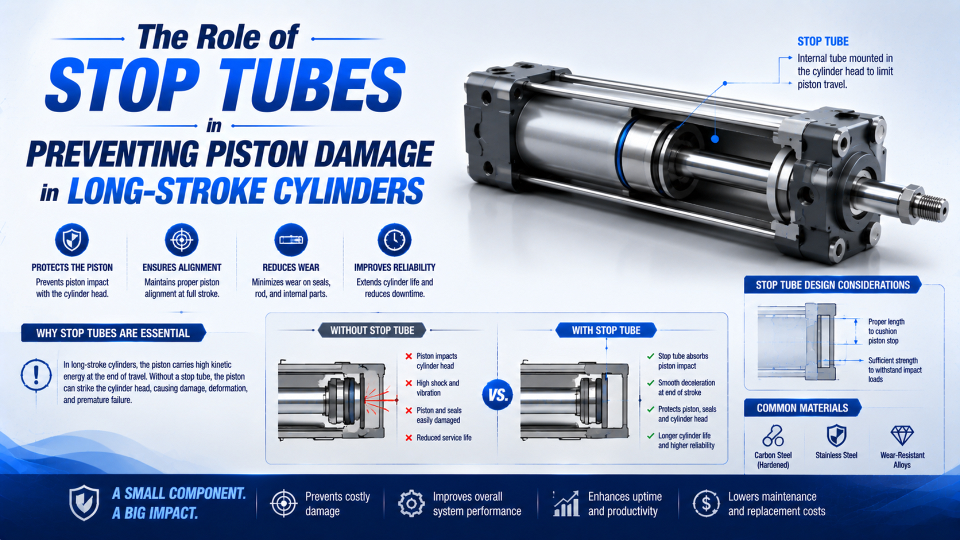
A stop tube is an internal spacer used in certain piston-rod cylinders.
At full extension, it keeps the piston farther from the rod-end bearing or bushing. Greater support separation lowers bearing load and stabilizes the long extended assembly.
That change can help prevent uneven wear, surface scoring, and secondary piston damage.
Stop tubes aren’t air cushions. They don’t create a long pneumatic braking chamber.
Their length should never be selected as a fixed percentage of cylinder stroke.
Selection depends on the cylinder series and mounting arrangement. Rod-end connection, load guidance, thrust, working stroke, and extra rod extension also belong in the decision.
ISO 15552 covers detachable-mount pneumatic cylinders with 32 mm to 320 mm bores and a maximum rated pressure of 1,000 kPa. It defines basic dimensions plus mounting and accessory dimensions. Its interchangeability scope does not prescribe one universal stop-tube length (ISO 15552:2018, confirmed 2025).
Key Takeaways
- Parker defines gross stroke as net stroke plus stop-tube length.
- Stop tubes reduce bearing stress by separating the piston and rod bearing at full extension.
- Parker’s 2A selection table uses stroke factors from 0.5 to 4.0, showing why stroke alone cannot set the required length.
- Cushioning, external shock absorption, wear-ring support, and rod buckling remain separate checks.
What Does a Stop Tube Actually Do?
Parker’s Series A air-cylinder catalog places stop tubing on page 55 and states that it increases the distance between the bushing and piston at full extension. That separation reduces bearing load, especially in horizontal and long-stroke cylinders (Parker Atlas Series A, 2020; retrieved 2026-07-22).
In a conventional single-rod cylinder, the piston guides the rod from inside the barrel while the rod bearing supports it at the head end. As the cylinder extends, both support points determine how the assembly responds to bending moment and alignment error. A stop tube prevents the piston from reaching the standard head-end position, so piston and rod bearing remain farther apart. That geometry explains the name. The tube stops the piston earlier within a cylinder built with additional internal length. Correctly specified gross stroke and cylinder envelope still give the machine its required working travel.
What does the tube not do? It doesn’t control deceleration.
Metering exhaust air belongs to a cushion sleeve and needle valve. Absorbing a moving load’s kinetic energy requires a suitable cushion, elastomeric stop, or external shock absorber selected for that impact duty.
How Does Added Bearing Separation Protect the Piston Assembly?
Two internal support regions share the extended rod’s lateral reaction: the piston inside the tube and the rod bearing in the head. Parker links a longer distance between them to lower bearing loads and added long-stroke stability (Parker Atlas Series A, 2020).
Imagine applying a small off-axis force at the rod end. That force creates a moment about the internal supports. When the support points are close together, a given moment requires larger reaction forces at those points. Increasing their separation can reduce those reactions, although the exact load distribution still depends on clearances, bearing lengths, component stiffness, mounting alignment, and external guidance. Stop-tube protection is therefore indirect. Lower bearing reaction can reduce edge loading at the rod bearing and piston guide surface, while wear bands and seals can also benefit. Less edge loading may reduce the chance that a tilted piston or rod scores the bore. It cannot make a cylinder tolerate unlimited side load.
Stroke by itself isn’t the useful design variable. Full-extension load-path geometry matters.
Record where the cylinder is supported and how the rod end is connected. Then establish whether the load is guided and how far the piston sits from the rod bearing.
Two cylinders with the same working stroke can need different stop-tube decisions.
This also explains why a stop tube is mainly associated with piston-rod cylinders. A mechanically coupled rodless cylinder uses a different force-transfer and guide arrangement. Its carriage loads and moments must be checked against that product’s own catalog rather than assuming a conventional stop tube is present.
Net Stroke, Gross Stroke, and Cylinder Envelope
Parker defines gross stroke as net stroke plus stop-tube length, a direct 1:1 dimensional addition that changes the cylinder’s envelope. Its 2A catalog also states that net stroke equals gross stroke minus stop-tube length (Parker 2A Series, retrieved 2026-07-22).
The relationship is:
is gross stroke. is the required net or working stroke, and is stop-tube length.
Keep all three values in the same length unit.
Gross stroke normally governs the longer cylinder construction. Net stroke is the travel available to the machine.
Suppose an axis needs 1,000 mm of usable movement and the selected manufacturer’s procedure requires a 100 mm stop tube. The ordered cylinder must accommodate 1,100 mm gross stroke while delivering 1,000 mm net stroke. That example explains only the dimensional relationship; it does not imply that 100 mm fits every 1,000 mm application. Why does this distinction matter during replacement? Ordering only the old machine’s visible travel can produce a cylinder that stops short. Using gross stroke as ordinary working stroke creates the opposite risk: the rod can move too far. Record net stroke and stop-tube length separately. Gross stroke, retracted pin-to-pin dimension, and extended envelope need their own fields too.
Added length can affect tie-rod spacing and sensor position. It may also shift an intermediate mount or change guarding, hose movement, and removal clearance.
Matching bore and mounting dimensions do not guarantee an interchangeable overall package once a stop tube is added.
When Should a Long-Stroke Cylinder Use a Stop Tube?
Parker’s 2A selection table assigns mounting and guidance stroke factors from 0.5 to 4.0, an eightfold range between the smallest and largest values. That spread shows why no single 24-inch, 600 mm, or 900 mm threshold can govern every application (Parker 2A Series, retrieved 2026-07-22).
Start the review when the cylinder has a long working stroke, operates horizontally, pushes under compression, carries an extended rod-end attachment, or uses a mounting arrangement that produces an unfavorable effective length. A guided load can behave very differently from a load supported only at the rod end.
The following conditions increase the need for a manufacturer check:
- Long net stroke or additional nonstandard rod extension.
- Horizontal installation with substantial rod, attachment, or load weight. Gravity then contributes a bending reaction that a vertical rod-up installation may not share.
- Compression thrust at or near full extension.
- Rod-end joints or machine guides that do not maintain coaxial motion through the complete travel.
- Pivot mounting, remote load support, or changing alignment through the stroke.
- High cycle count combined with visible one-sided bearing or seal wear.
- Replacement of an existing cylinder whose records do not clearly separate working travel, internal stop length, total stroke, and retracted installation dimensions.
Do you need a stop tube whenever one item appears? Not necessarily. Some mounting and guidance combinations produce favorable support, while others become severe at a shorter stroke. Use the chart and rules for the selected cylinder series, then ask the manufacturer for an application review when the point lies in a consult-factory region.
Peninsular provides a useful illustration of product-specific guidance. Its published method applies a particular increment above a calculated 40-inch length for the covered cylinder family, while its metric guidance asks users to consider stop tubes above 900 mm and still review mounting and load factors (Peninsular Rod Strength and Support; Peninsular Metric Air Cylinder Guidance, retrieved 2026-07-22). Those values are not universal rules for other brands.
How Do You Select Stop-Tube Length?
Parker’s 2A procedure uses four linked steps: identify mounting and rod-end connection, calculate basic length, determine thrust, and read rod diameter plus stop-tube length from the product chart. A “consult factory” result requires complete application data rather than graph extrapolation (Parker 2A Series, retrieved 2026-07-22).
For that catalog, the basic screening relationship is:
is basic length. is net stroke, and is the stroke factor assigned to the mounting and rod-end support case.
Nonstandard rod extension must be incorporated according to the selected catalog’s instructions. Never transfer Parker’s factors to a cylinder from another manufacturer.
The chart also uses thrust. A preliminary theoretical extension value is:
is theoretical extension thrust. is pressure differential across the piston, and is full piston area.
Use the pressure basis required by the manufacturer’s method.
Installed-machine diagnosis needs a wider force balance. Exhaust back pressure and friction can matter, along with acceleration, gravity, and external forces.
A practical selection sequence is:
- Define net stroke. State the exact machine travel, including tolerance and any adjustment range.
- Identify the cylinder series. Obtain the current stop-tube and rod-selection pages for that exact product.
- Classify mounting and rod-end support. Record fixed or pivot mounting, joint type, and whether the load is rigidly guided.
- Add nonstandard rod extension. Include spacers, long rod ends, load cells, couplers, and adapters where the method requires them.
- Determine the governing thrust case. Include a credible jam or hard-stop condition if full pressure can remain applied.
- Read both outputs. Select stop-tube length and piston-rod diameter together when the chart combines them.
- Confirm net and gross stroke. Put both in the quotation, drawing, and purchase order.
- Escalate chart limits. Ask the manufacturer to review any consult-factory region. Supply the side load, orientation, shock conditions, load guidance, machine geometry, and the consequences of a jam or loss of support.
A stop-tube chart is more than a spacer chart. It often belongs to a combined rod-diameter and long-stroke stability procedure.
Treating its length result as complete approval can leave the application with an undersized rod or unsuitable mount. End-of-stroke energy could remain excessive too.
From our analysis of the cited manufacturer methods, we found the same practical pattern: stop-tube length is an output of a defined application model, not a percentage chosen before mounting, guidance, thrust, and rod extension are known.
The Cylinder Force Calculator can organize a preliminary pressure-area estimate, but it cannot select stop-tube length. For compression stability, use the separate Cylinder Rod Buckling Calculator as a screen and still apply the selected cylinder manufacturer’s chart.
Stop Tube Versus Cushioning, Shock Absorbers, and Wear Rings
Parker discusses stop-tube selection on page 39 and cushioning on page 41 of its 2A catalog. It recommends cushioning for deceleration and identifies speeds above 0.1 m/s as one product-specific trigger, confirming that support geometry and end-of-stroke energy are separate engineering tasks (Parker 2A Series, retrieved 2026-07-22).
| Component or check | Primary function | What it does not prove |
|---|---|---|
| Stop tube | Increases piston-to-rod-bearing separation at full extension | Adequate end-of-stroke energy absorption |
| Adjustable pneumatic cushion | Restricts exhaust near end of stroke to decelerate the piston | Acceptable long-stroke bearing load |
| External shock absorber | Dissipates specified kinetic and propelling energy over its stroke | Correct rod diameter or cylinder alignment |
| Piston wear or guide ring | Carries transverse reaction and prevents metal contact in its designed assembly | Higher allowable machine side load than the catalog states |
| Rod buckling check | Screens a long extended rod under compression | Adequate cushioning or bearing life |
| External linear guide | Carries payload and moments when correctly aligned and rated | Automatic correction of a misaligned cylinder mount |
If the cylinder bangs at the end of travel, adding stop-tube length is not a substitute for calculating stopping energy. Review the pneumatic cylinder cushioning mechanism and, for higher energy, follow the external shock absorber sizing workflow. If inspection finds piston scoring or one-sided wear, determine whether the root cause is bearing load, machine misalignment, inadequate external guidance, a damaged wear ring, or impact. The piston wear-ring guide explains the separate guide-ring function. Some product families also use a different internal arrangement when a stop tube and head-end cushion are combined. Parker’s Series A catalog identifies a double-piston design for air cylinders with head-end or both-end cushioning. Never assume a loose generic tube can be retrofitted without changing the piston or cushion. Tie rods and the cylinder envelope may change as well.
What Other Long-Stroke Checks Remain Necessary?
Parker’s 2A method produces two separate long-stroke decisions: required piston-rod diameter and required stop-tube length. The same catalog says a long push stroke still needs sufficient column strength, while tensile load is not governed by stroke in the same buckling sense (Parker 2A Series, retrieved 2026-07-22).
Check these items independently:
- Rod buckling: Use the maximum credible compression force, effective length, end conditions, rod diameter, and the manufacturer’s permitted-stroke chart. The detailed piston-rod buckling guide covers that workflow.
- Cylinder mounting strength: Verify mount, pin, clevis, trunnion, tie rods, brackets, and fasteners for thrust and moment.
- Machine guidance: Keep payload side force and moment out of the piston rod unless the cylinder is rated to carry them. Check rail alignment at both ends and at mid-stroke under load.
- Alignment: Check the entire stroke, not only the retracted position. A long axis can bind only near full extension.
- End-of-stroke energy: Use actual moving mass and approach velocity, then confirm cushion or shock-absorber capacity.
- Flow and timing: A longer cylinder volume and changed cushion arrangement can affect fill time and cycle behavior.
- Sensors and guarding: Recheck target positions, cable routing, pinch points, access panels, and the extra clearance needed to remove the longer assembly without dismantling unrelated machine structure.
In our experience, the first symptom is often a damaged rod seal. Yet the cause sits outside the seal. A rigid rod-end connection, guide rail offset, or unsupported load creates the bending reaction. Replacing the seal and adding a stop tube won’t correct a machine that forces the rod to travel off-axis. Commission the axis at reduced pressure and speed when the machine risk assessment permits. Watch for binding and lateral rod movement first. Next check guide temperature, end impact, sensor position, and leakage. Confirm the worst intended load and pressure under controlled conditions, followed by maximum speed, orientation, and cycle rate.
What Belongs in a Stop-Tube RFQ?
Peninsular’s metric stop-tube guidance asks eight application questions. They cover orientation and rod guidance as well as load weight, external assistance, cycle rate, rod diameter, load direction, and mounting style. A useful RFQ answers them before requesting a length or retrofit recommendation (Peninsular Metric Air Cylinder Guidance, retrieved 2026-07-22).
Provide the following information in one drawing package or data sheet:
| RFQ field | What to state |
|---|---|
| Cylinder identity | Manufacturer, series, bore, rod diameter, serial or configuration code |
| Travel | Required net stroke, proposed stop-tube length if known, gross stroke, tolerance |
| Mounting | Exact mounting style, orientation, pivot geometry, intermediate-mount location |
| Rod end | Thread, clevis or spherical joint, extra extension, adapter stack, coupling method |
| Guidance | Guide type, support spacing, allowable play, alignment method, whether the load is rigidly guided |
| Loads | Push and pull force, moving mass, side load, moments, gravity direction, jam or stopper case |
| Air conditions | Minimum and maximum pressure at the cylinder, valve state during a jam, speed, cycle rate |
| End-of-stroke control | Cushion type, external shock absorber, hard stop, approach velocity |
| Environment | Temperature, contamination, washdown, corrosion, lubrication policy |
| Interfaces | Retracted and extended envelope, ports, sensors, guarding, service-removal space |
For a replacement, attach the old cylinder drawing. Add photographs of the rod-end connection, mount, and external guides. Measure usable machine travel rather than inferring it from barrel length. If the old part number contains both working and total stroke, preserve the manufacturer’s notation in the quotation. Our team found that replacement RFQs become easier to verify when net stroke, gross stroke, and stop-tube length appear as three separate fields. If the selected chart reaches a consult-factory region, send the complete drawing and load case through the engineering contact page. Don’t extrapolate the graph.
Can an existing cylinder be retrofitted? Sometimes, but the change may require a longer tube and tie rods, a different piston arrangement, modified cushion components, and revised sensor positions. Obtain written confirmation from the original manufacturer or a qualified replacement supplier before machining internal parts.
There is no defensible universal replacement interval for a stop tube. Inspect it when the cylinder’s service instructions call for teardown or when symptoms justify investigation. Scoring, looseness, deformation, transferred metal, fractured edges, and asymmetric contact are evidence to examine, but root cause and dimensional acceptance must come from the product drawing and service criteria.
FAQs About Stop Tubes in Long-Stroke Cylinders
The two manufacturer procedures cited here require at least five application inputs before a stop-tube decision. Those inputs include stroke and mounting plus rod-end support, thrust, and rod extension. These FAQs keep that product-specific approach and separate bearing support from cushioning and rod buckling (Parker Atlas Series A; Parker 2A Series, retrieved 2026-07-22).
At what stroke length is a stop tube required?
There is no universal stroke threshold. Parker assigns different stroke factors to different mounting and guidance cases, while Peninsular publishes rules for its own product families. Start with the exact cylinder catalog and application geometry. A shorter, poorly supported push installation can be more demanding than a longer, rigidly guided one.
Does a stop tube cushion the piston at the end of stroke?
No. A stop tube changes support geometry by separating the piston and rod bearing at full extension. Pneumatic cushioning restricts exhaust air to decelerate the piston, while an external shock absorber dissipates specified impact energy. A long-stroke design may require both support correction and a separately sized deceleration system.
How much longer does a stop tube make the cylinder?
For the Parker catalogs cited here, gross stroke equals net stroke plus stop-tube length, so the stroke-based envelope grows by the tube length. Other mounting and construction dimensions may also change. Confirm the selected model drawing, because sensor positions, tie rods, intermediate mounts, and removal clearance can be affected.
Can a stop tube prevent piston-rod buckling?
It can improve internal support separation and reduce bearing stress, but it does not replace a rod column-strength check. Parker’s long-stroke procedure reads rod diameter and stop-tube length as separate outputs.
Check maximum compression force and effective length independently. End conditions, rod diameter, and the manufacturer’s permitted-stroke data still govern the buckling decision.
Can a stop tube be added to an existing cylinder?
Only when the cylinder design and manufacturer permit it. A retrofit may need a longer barrel and tie rods, revised piston hardware, compatible cushion parts, and changed sensor locations. Adding a loose spacer without a product drawing can reduce working stroke, damage internal parts, or disable the intended cushion arrangement.
Sources and technical references
- Parker Atlas Series A Heavy Duty Industrial Air Cylinders, Catalog HY04-AC0910-5/US, stop tubing and mounting classes, pages 55-56.
- Parker 2A Inch Series Tie Rod Pneumatic Cylinders, Catalog HY07-0910/UK, piston rod sizes, stop tubes, stroke factors, and cushioning, pages 39-41.
- Peninsular Cylinder, Rod Strength and Support, stop-tube length example and rod-strength workflow.
- Peninsular Cylinder, Metric Air Cylinder Stop-Tube Guidance, application data and stop-spool notes.
- ISO 15552:2018, detachable-mount pneumatic cylinder dimensions and scope.