

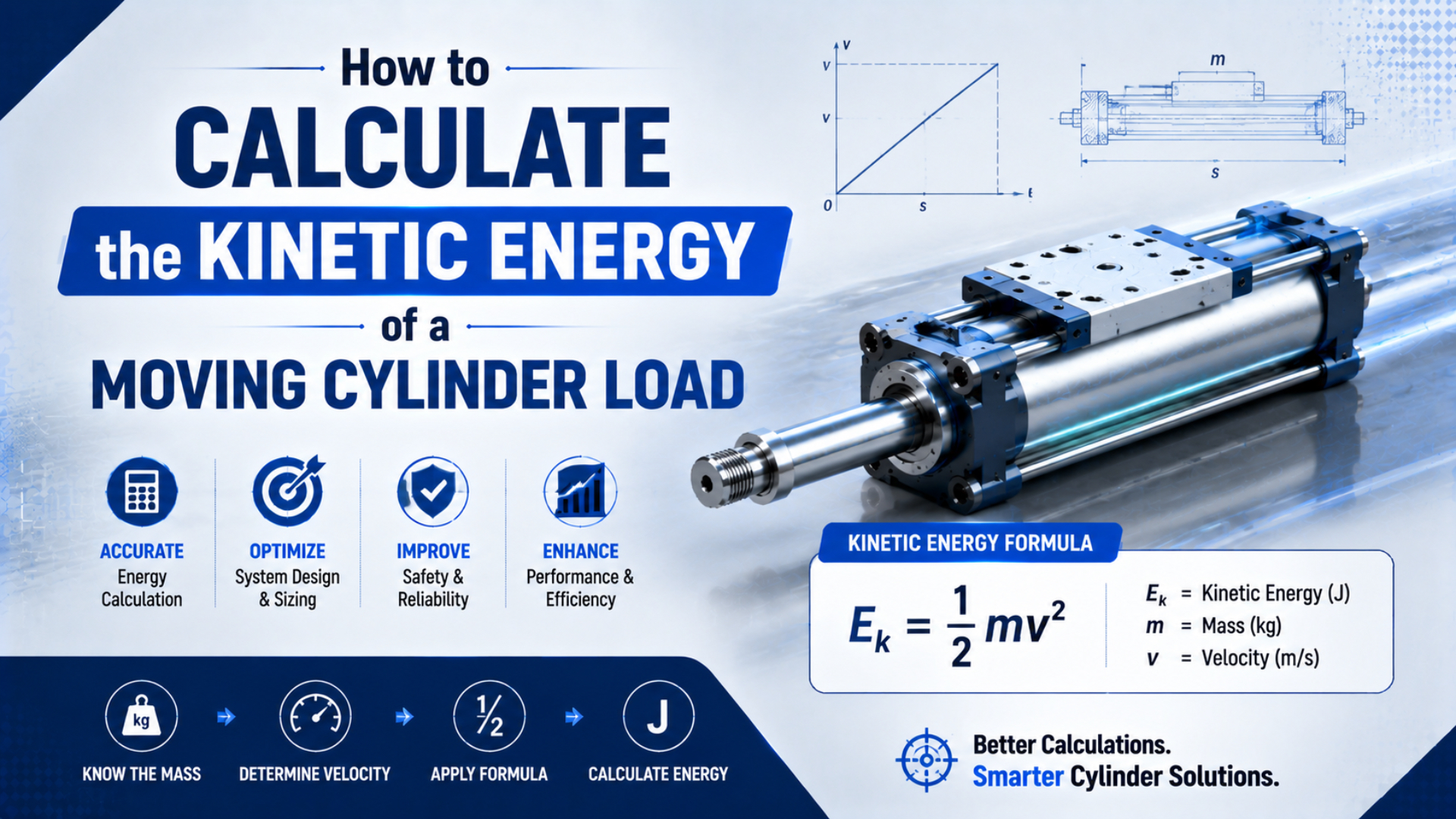
Calculate a moving cylinder load’s kinetic energy with one-half of the total moving mass multiplied by the square of its speed. Use the speed at cushion entry or impact, not automatically the average stroke speed. Then compare the result with the exact cylinder cushion or shock absorber data for the selected model.
That calculation is a screening step, not a complete claim about peak force. A stop may also absorb work from continuing pneumatic drive force and gravity. For the full stopping-energy and load-path method, use the related end-of-stroke force guide.
Moving mass is every component translating with the cylinder load. Cushion-entry speed is the speed when end cushioning begins. Allowable kinetic energy is the model-specific catalog limit that the selected cushion or bumper may absorb under stated conditions.
Key Takeaways
- Kinetic energy rises with the square of speed.
- Parker says cushion-entry speed can be 50% above average speed.
- Include moving cylinder parts, tooling, brackets, and product.
- Compare joules with the exact model’s published limit.
What Does Kinetic Energy Mean for a Moving Cylinder Load?
NIST defines translational kinetic energy as one-half of mass times velocity squared and names the SI result the joule, or J. That gives a cylinder designer 3 linked quantities to check: total moving mass in kilograms, impact or cushion-entry speed in metres per second, and energy in joules (NIST, retrieved 2026-07-19).
For a load moving in a straight line, use:
Here, is kinetic energy in joules, is total moving mass in kilograms, and is cushion-entry or impact velocity in metres per second. The formula assumes translational motion. A rotating arm, pulley, or crank may require rotational inertia or reflected-mass calculations as well.
The SI unit check is:
That unit identity is useful for catching mixed inputs. Kilograms and metres per second produce joules directly. Pounds, feet per second, millimetres per second, or kilogram-force need conversion before they enter an SI calculation.
Kinetic energy describes the energy carried by the moving assembly at one instant. It doesn’t reveal the maximum force at a bracket, the pressure spike inside a cushion, or the stopping time. Those results depend on how the energy is removed and how the reaction travels through the machine.
Which Mass Must Go Into the Calculation?
Parker’s heavy-duty cylinder guidance requires the load plus piston and rod mass, and its worked example grows an 85 lb payload to a 99 lb moving total after cylinder parts are included. The exact addition is model-specific, so use drawings, measured hardware, and the selected cylinder’s mass data instead of a generic percentage (Parker, retrieved 2026-07-19).
Build the mass inventory around what actually translates along the motion axis:
| Moving item | Preferred evidence | Frequent mistake |
|---|---|---|
| Product or workpiece | Scale, bill of materials, controlled payload specification | Using a nominal product weight when recipes vary |
| Tooling and fixture | Assembly drawing or measured subassembly | Omitting grippers, clamps, nests, and adapters |
| Mounting plate and fasteners | CAD mass property checked against purchased hardware | Treating the plate as stationary |
| Piston, rod, or carriage | Exact manufacturer model data | Copying mass from another bore or stroke |
| Cable carrier or hose contribution | Motion review or measured effective contribution | Adding the entire stationary assembly without checking motion |
| Coupled mechanism | Kinematic model or reflected mass | Ignoring a belt, pulley, linkage, or vertically lifted member |
For a simple direct-axis assembly:
Each term uses kilograms. Don’t add a stationary cylinder body, fixed frame, or full hose length merely because it belongs to the machine. Conversely, don’t omit a moving carriage or rod because its mass isn’t shown on the payload drawing.
In our experience, the cleanest worksheet assigns an owner and evidence source to every mass term. Purchasing may own product variation, mechanical design may own tooling mass, and the cylinder supplier may own piston or carriage data. That makes a later payload or model change visible instead of silently invalidating the result.
For vertical systems, the mass inventory remains the same, but gravity can add work during downward stopping. The vertical cylinder selection guide covers load holding and orientation concerns that a kinetic-energy number alone cannot settle.
How Do You Calculate Kinetic Energy Without a Unit Error?
The NIST relationship produces 100 J for a 50 kg moving assembly traveling at 2 m/s because one-half times 50 times 2 squared equals 100. The arithmetic is simple, but the result is defensible only when mass and speed describe the same worst credible operating condition (NIST, retrieved 2026-07-19).
Use this calculation sequence:
- List every translating component and total the mass in kilograms.
- Establish the speed at cushion entry or impact in metres per second.
- Square the speed before multiplying by mass.
- Multiply by one-half and report the result in joules.
- Record the payload, direction, recipe, and measurement condition beside the result.
Suppose a 12 kg assembly approaches the stop at 0.8 m/s:
If the speed was recorded in millimetres per second, convert first. For example, equals . Squaring 800 as though it were metres per second would make the result one million times too large.
Mass and weight are also different quantities. Enter kilograms as mass. Don’t enter newtons, kilogram-force, or pounds-force in the field. When a catalog uses pounds as a practical load label, follow that manufacturer’s graph and unit convention rather than mixing it with an SI formula.
The pneumatic cylinder theoretical force guide answers a different question. Pressure times effective piston area estimates cylinder force; mass times speed squared estimates moving energy. Neither calculation can replace the other.
Why Does Cushion-Entry Speed Matter More Than Average Speed?
Parker states that piston speed at the start of cushioning is typically about 50% higher than average stroke speed. Since velocity is squared in the kinetic-energy equation, using average speed in that situation would produce only about 44% of the energy calculated from a speed that is 1.5 times higher (Parker, retrieved 2026-07-19).
Average stroke speed is often estimated as:
is stroke distance and is travel time. This average hides acceleration, valve opening, pressure buildup, load variation, friction, and the actual motion profile near the end of stroke. It is useful for cycle-time planning, but it isn’t automatically the correct cushion-selection input.
The energy ratio between two speeds is:
If the mass stays constant and speed doubles, kinetic energy becomes four times larger. A 10% speed increase raises energy by 21%. That square-law sensitivity is why a small flow, pressure, or payload change can erase an apparently comfortable cushion margin.
Measure speed close to cushion entry when the margin is tight. A position sensor with timestamps, encoder, high-speed camera, or validated motion trace may be suitable, depending on accuracy and risk. The cylinder speed calculator can support an early flow-based estimate, but measured production motion remains the stronger selection input.
Worked Example: A 50 kg Load at 2 m/s
A 50 kg moving assembly at 2 m/s carries 100 J of translational kinetic energy under the NIST equation. The result matches the arithmetic in the source article, but it doesn’t prove that a cylinder end cap, mounting bracket, or external absorber can safely stop the load (NIST, retrieved 2026-07-19).
Assume the 50 kg total already includes the carriage, tooling, mounting plate, fasteners, and product. Use the measured cushion-entry speed of 2 m/s:
Now test the sensitivity. If the actual entry speed is 2.2 m/s rather than 2.0 m/s:
A 10% speed error raises the energy from 100 J to 121 J. If mass increases by 10% instead, energy increases linearly to 110 J. This comparison shows why velocity verification deserves more attention than adding an unsupported blanket mass percentage.
Record the 100 J result as “translational kinetic energy at cushion entry,” not “impact force” or “required cylinder force.” A label is part of the engineering control. It stops a correct energy number from being reused later as though it were a peak structural load or a complete cushion selection.
When Is Kinetic Energy Not the Whole Stopping-Energy Budget?
ACE’s official calculation basis shows a 100 kg load at 2 m/s carrying 200 Nm of kinetic energy, then adds 200 Nm of propelling-force work to reach 400 Nm per cycle. In SI energy terms, Nm and J are equivalent, so continuing cylinder thrust can double that example’s absorber duty (ACE Controls, retrieved 2026-07-19).
If compressed air keeps driving the piston through the stopping distance, approximate the additional work as:
is drive work in joules, is net drive force during stopping in newtons, and is effective stopping distance in metres. Use pressure measured or defensibly estimated during motion, not only the regulator’s static value.
For a broader first-pass budget:
is energy the stopping device must absorb per event. is gravity work, positive when gravity drives the load into the stop and negative when gravity resists approach. Linkage geometry, springs, process forces, or multiple absorbers may require additional terms.
Keep the first calculation on . Once drive work, gravity, stopping distance, average resisting force, or peak structural load becomes the decision, move to the complete end-of-stroke energy worksheet. That boundary prevents a screening calculation from being mistaken for a complete stop design.
How Should You Compare the Result With a Cylinder Cushion Rating?
SMC’s model-selection guide lists only 0.07 J of air-cushion capacity for one 10 mm-bore CJ2 example and 0.18 J for its 16 mm counterpart. Those model-specific values show why bore, cushion type, speed range, and exact series must be checked before treating a calculated energy as acceptable (SMC, retrieved 2026-07-19).
Use the calculated kinetic energy as one side of a catalog comparison:
is the energy basis required by the manufacturer. It may be kinetic energy alone or a larger absorbed-energy value that includes drive and gravity work. is the exact published limit for the selected model, bore, direction, cushion, mounting, and operating condition.
Check more than one number:
| Catalog check | Why it matters |
|---|---|
| Allowable energy per event | Screens the immediate stop |
| Mass-speed chart or envelope | Confirms the mass and impact-speed combination |
| Effective mass range | Checks whether the absorber’s force profile fits the application |
| Energy per hour or cycle rate | Screens heat buildup and repeated operation |
| Cushion stroke or effective length | Defines the distance available for energy absorption |
| Direction and mounting notes | Captures gravity, side load, alignment, and model restrictions |
Festo identifies 5 operating inputs for adjustable pneumatic cushioning: moving mass, speed at damping, target deceleration, working pressure, and cylinder resistance. Those variables explain why an adjustment screw cannot replace the model’s capacity check or compensate for an energy level outside the approved operating range (Festo, 2022, retrieved 2026-07-19).
Don’t repair an exceeded catalog limit by inventing a universal safety factor. The next action is architectural: lower entry speed, reduce mass, increase rated stopping capacity, add a correctly sized external absorber, or change the stop location. A multiplier cannot create cushion stroke, thermal capacity, or alignment.
The calculator is a screening aid. The selected cylinder or shock absorber manufacturer’s instructions and model data remain the acceptance basis.
A Practical Moving-Load Energy Worksheet
ACE separates kinetic energy per cycle, propelling-force energy, total energy per cycle, and total energy per hour into 4 distinct results. A useful cylinder worksheet should preserve that separation while recording the mass, impact speed, stopping distance, orientation, cycle rate, and exact catalog capacity used for the decision (ACE Controls, retrieved 2026-07-19).
Use one row for every direction and operating condition that can reach a stop:
| Worksheet field | Unit | Evidence to retain |
|---|---|---|
| Total moving mass | kg | Mass inventory, drawing revision, payload condition |
| Cushion-entry or impact speed | m/s | Measurement method, trace, or documented estimate |
| Translational kinetic energy | J | Formula and calculation revision |
| Net drive force through stop | N | Dynamic pressure and effective area basis |
| Effective stopping distance | m | Catalog cushion length or absorber working stroke |
| Orientation and gravity direction | degrees or direction | Machine layout and motion direction |
| Stops per hour | 1/h | Sustained worst production recipe |
| Exact model capacity | J/event and J/h | Datasheet revision and manufacturer conditions |
| Acceptance margin | J or percent | Approved design rule, not a generic factor |
Run separate cases for extend and retract. The effective piston area changes, gravity may change sign, and tooling may contact the process in only one direction. If payload and speed vary independently, test the worst credible combination rather than assuming that the heaviest product always moves at the normal recipe speed.
Finally, verify the installed machine. Confirm that the piston doesn’t strike hard, the cushion setting stays inside the manufacturer’s instructions, the external absorber is aligned, the load guide carries side moments, and the production trace matches the calculation input. The pneumatic cushioning guide explains adjustment symptoms and cushion mechanisms.
Moving Cylinder Load Kinetic Energy FAQs
Parker’s 50% cushion-entry speed warning and SMC’s model-specific 0.07 J and 0.18 J CJ2 examples explain why one formula cannot select every stopping device. These answers keep the basic kinetic-energy calculation separate from catalog capacity, total absorbed energy, average force, and measured peak load (Parker; SMC, retrieved 2026-07-19).
What is the formula for a moving cylinder load’s kinetic energy?
Use . Enter total moving mass in kilograms and cushion-entry or impact speed in metres per second; the result is joules. The formula covers translational kinetic energy only. Rotating mechanisms, continuing cylinder drive, gravity, and springs may require additional terms.
Which parts count toward total moving mass?
Include the product, tooling, fixtures, moving mounting plates, fasteners, piston and rod or carriage, and any mechanism whose motion is reflected into the cylinder axis. Exclude the stationary body and frame. Use exact drawings, measurements, or model data instead of assuming a fixed percentage above payload mass.
Should I use average stroke speed in the calculation?
Use measured cushion-entry or impact speed whenever possible. Parker says speed at the start of cushioning is typically about 50% higher than average stroke speed. Stroke divided by time can support an early estimate, but it hides acceleration and may understate the squared velocity term used for cushion selection.
Does doubling cylinder speed double kinetic energy?
No. With mass unchanged, doubling speed makes kinetic energy four times larger because velocity is squared. A 10 kg assembly carries 5 J at 1 m/s and 20 J at 2 m/s. Recalculate the energy whenever valve flow, pressure, payload, or cycle settings can change entry speed.
Is calculated kinetic energy enough to select a cylinder cushion?
Not always. Compare the result with the exact model’s mass-speed envelope and allowable energy, then check whether drive force, gravity, cycle rate, stopping distance, or effective mass must also be included. Use the manufacturer’s selection method and test the installed motion under the worst credible production condition.
Sources and technical references
- NIST, “NIST Guide to the SI, Chapter 7: Rules and Style Conventions for Expressing Values of Quantities,”
https://www.nist.gov/pml/special-publication-811/nist-guide-si-chapter-7-rules-and-style-conventions-expressing-values. Supports the kinetic-energy equation, SI dimensions, and joule. Retrieved 2026-07-19. - Parker Hannifin, “OSP-P Pneumatic Rodless Cylinders and Linear Guides” and “Heavy Duty Pneumatic Cylinders Series 2A/2AN.”
https://www.parker.com/content/dam/Parker-com/Literature/Pneumatics-Division-Europe/PDE-Documents/Cylinders/Parker_Pneumatic_OSP-P_Linear_Drive_System_Catalogue---PA4P011GB.pdf;https://www.parker.com/content/dam/Parker-com/Literature/Industrial-Cylinder/HY08-0910-1NA.pdf. Supports cushion-entry speed, total moving mass, and mass-speed selection. Retrieved 2026-07-19. - SMC, “Best Pneumatics: Air Cylinders Model Selection,”
https://www.smcworld.com/catalog/BEST-Guide-en/pdf/2-m27-49_en.pdf. Supports model-specific allowable kinetic energy and cushion selection. Retrieved 2026-07-19. - ACE Controls, “Calculation Basis Industrial Shock Absorbers,”
https://www.acecontrols.com/us/cad-downloads/knowledge/calculation-bases-for-the-design-of-industrial-shock-absorbers.html. Supports kinetic, propelling-force, per-cycle, hourly-energy, and effective-mass calculations. Retrieved 2026-07-19. - Festo, “Cylinder cushioning: the three most common methods,”
https://www.festo.com/gb/en/e/about-festo/blog/in-practice/cylinder-cushioning-the-three-most-common-methods-id_1518838/. Supports cushioning methods and the operating inputs for adjustable pneumatic cushioning. Published 2022; retrieved 2026-07-19.