

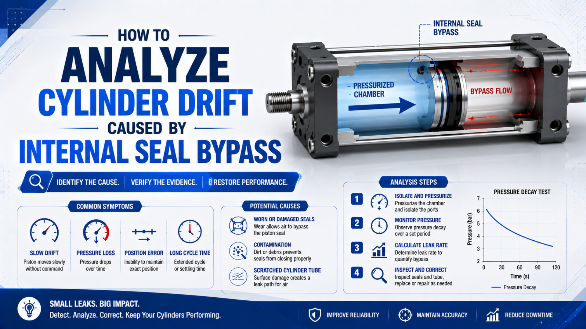
Cylinder drift caused by internal seal bypass should be diagnosed as an evidence chain, not assumed from rod movement alone. Record position and both cylinder-port pressures, reproduce the drift in a defined valve state, then separate the cylinder from the valve with an approved test fixture. Piston bypass is confirmed only when leakage remains across the piston boundary after competing paths have been excluded.
That distinction matters because a worn valve spool, changing supply pressure, exhaust restriction, external load, guide friction, or trapped pressure can move the same rod. Parker specifically warns that apparent piston leakage indicated by cylinder drift is not always traceable to the piston (Parker Pneumatic Actuator Products, accessed 2026).
This guide focuses on diagnosing the drift symptom. Use the separate internal-leakage causes and repair guide for a broader component inspection, and the internal-leakage cost guide only after measured flow and pressurized duty are known.
Publisher and author information is available on About Us. Technical corrections and application questions can be submitted through Contact.
Key Takeaways
- Drift identifies movement, not cause.
- Record position and both chamber pressures before disturbing the circuit.
- Compare measured leakage with the exact cylinder specification, not a universal PSI-per-minute rule.
- Use pressure decay only after controlling every competing leakage path, test volume, valve boundary, and temperature effect.
Drift Is a Symptom, Not a Component Diagnosis
Parker permits 1 to 3 in³/min of piston leakage for certain piston-ring constructions while expecting virtually no static leak from piston lip seals (Parker Pneumatic Actuator Products, accessed 2026). The contrast proves that drift cannot be judged against one universal leakage percentage or pressure-drop table.
Internal seal bypass is airflow from one working chamber to the other across the piston sealing interface. It is different from air escaping around the rod seal, through an end-cap joint, from a fitting, or inside the directional valve. The visible result may look similar, but the repair boundary is different.
Start by describing the machine state precisely:
- Which port is supplied, exhausted, or blocked?
- Is the load horizontal or vertical, and does a spring, clamp, product, counterweight, or linkage add force during the dwell?
- Does the piston begin at the end cap or at mid-stroke?
- Is the cylinder cold, thermally stable, or recently cycled?
- Does drift stop when the valve center state changes, pilot supply is removed, controller output freezes, or contact with the external process is released?
A cylinder with both work ports blocked may drift as its chamber pressures move toward equilibrium. A cylinder held with one chamber supplied and the other exhausted can show continuous bypass flow. A vertical cylinder may also move because the pneumatic force margin falls below the gravitational load, even when the leakage rate itself is small.
| Observed symptom | Internal bypass is possible when | A competing explanation remains when |
|---|---|---|
| Rod moves during dwell | pressure difference decays and cylinder-only leakage is measured | valve leakage, controller correction, or load change has not been excluded |
| Position changes after shutdown | trapped chamber pressures equalize | stored load energy or gravity can move the axis |
| Holding force falls | pressure differential across the piston falls | supply pressure collapses or exhaust back pressure rises |
| Motion becomes jerky | damaged seals or bore increase friction and leakage | guides bind, lubrication changes, or speed controls stick |
| Drift changes with rod position | bore damage or side load varies along the stroke | external linkage geometry changes the applied load |
Treat drift as a boundary-identification problem. Position tells you that the piston moved. Pressure tells you whether useful force changed. A cylinder-only leakage test tells you whether air crossed the piston boundary. None of those measurements can replace the other two.
Why Does Internal Seal Bypass Move the Piston?
Parker expects virtually no static leakage from a lip-seal piston but accepts 1 to 3 in³/min for some piston-ring designs (Parker Pneumatic Actuator Products, accessed 2026). Whether that flow causes visible drift depends on valve state, chamber pressure, effective areas, friction, and external load.
The piston moves when the net force no longer balances. For a double-acting single-rod cylinder, a useful static screening relationship is:
Here, and are the measured absolute or gauge pressures on the two sides, provided the same basis is used. and are their effective piston areas, is the external load in the positive motion direction, and is the resisting friction. The sign convention must match the selected drift direction.
Internal bypass changes and . In a blocked-center hold, air moving from the higher-pressure chamber toward the lower-pressure chamber reduces the pressure difference until the external load overcomes friction. With one chamber supplied and the other exhausted, the pressure source may keep replacing bypassed air, so movement and continuous consumption can occur together.
Static friction complicates the first movement. The rod may appear stable while pressures change, then move suddenly when the remaining force margin crosses the breakaway threshold. That behavior is why a single final position reading can hide the earlier pressure event. The breakaway-force guide explains the difference between initial motion and steady sliding force. The same pressure change does not produce the same drift in every direction. Retraction uses the annular rod-side area, while extension uses the full piston area. Gravity, guide preload, seals, and linkage geometry may also reverse or amplify the effect. Record both drift direction and cylinder orientation.
A Safe Test Boundary Comes First
OSHA 29 CFR 1910.147(d)(5)(i) requires potentially hazardous stored or residual energy to be relieved, disconnected, restrained, or otherwise rendered safe before servicing (OSHA hazardous-energy standard, accessed 2026). Pneumatic pressure and a supported load are separate energy sources, so both need a documented control method.
Only qualified personnel should perform a pressurized functional test. Follow the machine builder’s energy-control procedure, lower or mechanically restrain suspended loads, isolate other actuators that share the circuit, and use a guarded manifold or the cylinder manufacturer’s approved fixture. Do not loosen a live tube merely to listen at the opposite port.
Separate the work into two modes:
- De-energized inspection: isolate the machine, relieve stored pressure, verify zero-energy state, inspect the rod, mountings, guides, fittings, tube condition, and accessible seal areas.
- Controlled diagnostic test: restore only the energy needed for the approved test, keep personnel outside the motion hazard, collect pressure and position data, then return the equipment to a verified safe state before changing connections.
Record the test boundary before collecting data:
| Field | Required record |
|---|---|
| Cylinder | manufacturer, complete model code, bore, rod, stroke, seal option |
| Circuit | valve type and center condition, regulator setting, speed-control orientation |
| Load | magnitude, direction, gravity effect, external springs or clamps |
| Initial state | piston position, supplied port, exhausted or blocked port |
| Instrumentation | pressure-sensor range and location, position resolution, sample interval |
| Environment | air and component temperature, recent cycle history, contamination evidence |
| Test controls | mechanical restraint, exclusion zone, isolation and re-energization procedure |
ISO 10099:2001 defines final examination and acceptance criteria for double-acting single-rod pneumatic cylinders and remains confirmed by ISO (ISO 10099:2001, confirmed 2023). It supports a basic principle: acceptance belongs to a stated test method and cylinder type, not an improvised field threshold.
How Do You Separate Piston Bypass from Valve Leakage?
One SMC actuator manual lists 10 cm³/min ANR internal leakage and 5 cm³/min ANR external leakage as model-specific allowable values (SMC CP80-TFR12, 2013). The two limits distinguish chamber-to-chamber flow from atmospheric loss and should not be generalized to every cylinder.
Begin with the assembled circuit because that is where the machine fails. Place pressure sensors as close as practical to both cylinder ports and measure position on the same time base. Hold the exact valve state that produces drift. If the controller automatically corrects position, disable that correction only under the approved test procedure or record its output so the added air is visible.
Then change one boundary at a time:
- Check fittings, end caps, rod gland, tubing, and valve exhaust for external leakage.
- Record both port pressures and position.
- Repeat with the same initial position, load, temperature, and dwell time.
- Separate the cylinder from the directional valve with the specified guarded test manifold, following the machine’s isolation, restraint, re-energization, and verification procedure.
- Pressurize the designated chamber and measure leakage at the opposite cylinder port.
- Reverse direction because seal loading and bore condition may differ along the stroke.
- Compare the result with the exact manual, drawing, purchase specification, or documented new-condition baseline.
Parker recommends pressurizing one side of the piston and observing the opposite port; if no leakage is evident, the drift cause should be sought elsewhere in the circuit (Parker Pneumatic Actuator Products, accessed 2026). Use the manufacturer’s approved implementation of that principle. Connection changes under pressure are not a shortcut.
Pressure decay can add a quantitative screening value when the isolated volume is known and temperature has stabilized. For an approximately isothermal test, normalized leakage can be estimated as:
Here, is normalized leakage volume per unit time, is the known isolated volume, is elapsed time, and are absolute start and end pressures, and are the selected reference conditions, and is the measured gas temperature.
Use consistent units.
The calculation reports loss from the test volume. It does not identify where the air went. If the test valve, fittings, rod gland, or end-cap seals remain inside the boundary, their leakage is included. A valid piston-bypass diagnosis therefore needs both measured loss and a boundary that excludes competing paths.
Use boundary substitution, not assumption. First record the valve-plus-cylinder system. Next replace the valve boundary with a verified test fixture while keeping the cylinder, position, direction, and load condition as consistent as possible. If the leakage signature follows the cylinder, piston bypass becomes credible. If it disappears, keep the cylinder closed and investigate upstream.
How Should You Measure Cylinder Drift Rate?
ISO 10099:2001 is a four-page standard covering final examination and acceptance criteria for double-acting single-rod pneumatic cylinders, and ISO confirmed it again in 2023 (ISO 10099:2001). It does not create one universal millimetres-per-hour limit for every machine, so drift must be tied to the application requirement.
Measure position against a stable machine reference, not against a guard, hose, or flexible bracket. Record the sensor resolution, repeatability, mounting stiffness, sample interval, and the threshold used to distinguish movement from noise. A dial indicator can support a controlled maintenance check; a linear encoder or displacement sensor is better when the event is fast or needs synchronized pressure data.
Calculate average drift speed over a stated interval with:
Here, is average drift speed, and are positions at times and , and both position and time units must be reported. Average speed does not show stick-slip motion, so retain the complete trace whenever the piston pauses and jumps.
Use a repeatable record rather than an unsupported “acceptable drift” table:
| Test item | What to state |
|---|---|
| Start position | end position or measured mid-stroke coordinate |
| Valve state | supplied, exhausted, blocked, or actively controlled ports |
| Load state | force, mass, direction, fixture condition, gravity component |
| Pressure | both cylinder ports plus dynamic supply when relevant |
| Temperature | cylinder surface, ambient air, and warm-up condition |
| Time interval | start event, end event, dwell length, sample rate |
| Position result | total displacement, direction, average rate, trace shape |
| Repetition | number of runs, minimum, median or mean, maximum |
One result is not enough when seals warm, lubricant redistributes, or supply pressure cycles. Repeat from the same starting position, then repeat at other positions if bore scoring or guide alignment is suspected. A longitudinal scratch may create a stronger leak signature only where the piston seal crosses it. Define acceptance from the machine function. A packaging registration axis, a transfer stop, and a noncritical horizontal pusher can tolerate different movement. A pneumatic cylinder must never be treated as the sole safety restraint for a suspended or hazardous load. Use a mechanical lock, rod lock, brake, counterbalance, or other risk-assessed device where loss of pressure can create danger.
Reading Pressure and Position Traces
Parker states that apparent piston leakage shown by drift may originate in other circuit components and recommends checking the opposite port under a controlled single-side pressure test (Parker Pneumatic Actuator Products, accessed 2026). Synchronized pressure and position traces show which event occurred before the rod moved.
Interpret sequence, not only final values:
- Pressures converge before movement: investigate cross-port flow, but do not assign its boundary yet.
- One pressure falls while the other stays unchanged: atmospheric leakage, supply loss, or a test-boundary leak may be more likely than direct piston equalization.
- Pressures remain stable but position moves: check external load, mounting compliance, mechanical slip, measurement reference, and controller action.
- Position jumps after a quiet pressure change: static friction held the piston until net force crossed the breakaway threshold.
- Drift appears only with the valve connected: investigate valve spool leakage, pilot state, pilot exhaust, work-port exhaust, control outputs, and any pressure-maintaining circuit before rebuilding the cylinder.
The most useful timestamp is often not the final drift position. It is the instant when position first departs from the noise band. Compare that point with the pressure-difference trace. The gap reveals whether pressure changed gradually before breakaway or whether an external mechanical event moved the axis first.
If the driving-side pressure collapses during normal motion rather than during a static hold, check the system pressure-drop path before replacing seals. If drift changes after a lubricant, cleaner, or process chemical change, review seal compatibility and the complete cylinder sealing-system guide.
When Should You Repair the Seal, Rebuild the Cylinder, or Investigate Elsewhere?
Festo reports that one cubic metre of untreated ambient air can contain up to about 180 million particles from 0.01 to 100 µm and links contamination to cylinder-wall wear, piston-seal damage, and internal leakage (Festo contamination guidance, accessed 2026). A seal replacement will not cure the surface or system condition that damaged it.
Repair the sealing set when the leakage boundary is confirmed, the bore and rod surfaces remain within specification, guides and mountings are sound, and the correct model-specific kit and procedure are available. Inspect the removed parts before discarding them. One-sided wear points toward side load or alignment; a cut lip suggests installation damage; swelling suggests chemical incompatibility; embedded debris points toward cleanliness or air-quality problems.
Rebuild or replace more than the seals when the bore is scored, corroded, tapered, or dimensionally worn; the rod or carriage is damaged; guides permit excessive side movement; static sealing surfaces are damaged; or the same failure has returned after a documented repair. Compare actual parts, labour, test time, downtime, expected service life, and replacement availability. Do not apply a universal age or percentage-of-new-cost rule.
Investigate elsewhere when the cylinder-only leakage test passes:
- Directional-valve spool or poppet leakage
- Pilot pressure, solenoid command, or controller output changing during the dwell while the mechanical load remains nominally stationary
- Regulator droop or unstable branch pressure
- Meter-out restriction or blocked exhaust silencer
- Mechanical brake, clamp, coupling, or guide slip
- Thermal movement in the machine frame, sensor bracket, guide, fixture, or reference target during the measurement interval
- Load variation, gravity, spring force, or process contact
- Position sensor movement, loose mounting hardware, electrical scaling drift, insufficient resolution, or an unstable measurement target that moves independently of the piston
Repeated contamination-related failure calls for a measured air-quality requirement. ISO 8573-1 classifies purity by particles, water, and oil; it does not prescribe one universal class for every cylinder (ISO 8573-1:2010, 2010). Use the ISO compressed-air quality guide to define the point-of-use condition from the cylinder and process requirements.
Create a repair acceptance record with the same position, load, temperature, valve state, port-pressure channels, drift interval, and cylinder-only leakage method used before the work. A different post-repair method may look better while hiding the original failure. Comparable before-and-after boundaries are more valuable than an undocumented “no drift observed” note.
Cylinder Drift FAQs: What Should Technicians Ask?
Parker’s 1 to 3 in³/min piston-ring guidance and SMC’s 10 cm³/min ANR model example use different constructions and units (Parker; SMC). These answers therefore rely on controlled boundaries and model specifications instead of universal drift or pressure-drop limits.
Does cylinder drift prove that the piston seal is leaking?
No. Drift proves that the piston changed position. Valve leakage, changing supply pressure, exhaust back pressure, gravity, external force, mechanical slip, or measurement movement can produce the same symptom. Record both port pressures and position, then test the cylinder separately with the manufacturer’s approved fixture before assigning the fault to internal seal bypass.
Can a pressure-decay test identify internal seal bypass by itself?
No. Pressure decay shows that air left a known isolated volume. It does not identify whether the path crossed the piston, escaped through a rod or end-cap seal, leaked from a fitting, or returned through the test valve. Control those boundaries first, stabilize temperature, then compare the calculated flow with the exact cylinder specification.
How much cylinder drift is acceptable?
There is no universal millimetres-per-hour limit. Acceptance depends on machine function, load direction, valve state, measurement uncertainty, safety analysis, and the cylinder or machine specification. Define a position band and test interval for the application. Never rely on a pneumatic chamber alone to secure a suspended or hazardous load.
Why should both cylinder-port pressures be recorded?
Cylinder force comes from the pressure difference acting on unequal effective areas. One gauge can miss rising pressure in the opposing chamber, exhaust restriction, or valve leakage. Two synchronized pressure channels plus position show whether the force margin changed before motion and provide a stronger basis for deciding which boundary to isolate next.
Should a drifting cylinder receive new seals or be replaced?
Replace seals when bypass is confirmed and the bore, rod, guides, mountings, and sealing surfaces remain serviceable. Rebuild or replace the actuator when scoring, corrosion, bent parts, excessive guide wear, or repeat failure remains. If the cylinder-only test passes, keep it closed and investigate the valve, circuit, load, and measurement reference.
Sources and technical references
- Parker Hannifin, Pneumatic Actuator Products: construction-specific piston-leakage guidance and the cylinder-versus-circuit drift test. Retrieved 2026-07-22.
- SMC, CP80-TFR12 Installation and Maintenance Manual: model-specific internal and external leakage limits and qualified-maintenance requirements. Retrieved 2026-07-22.
- ISO 10099:2001, Pneumatic fluid power: Cylinders: Final examination and acceptance criteria: scope and current confirmed status. Retrieved 2026-07-22.
- OSHA, 29 CFR 1910.147: The control of hazardous energy: control of stored and residual pneumatic energy. Retrieved 2026-07-22.
- Festo, Compressed air contamination: risks, impacts and solutions: particle ranges and contamination-related seal and bore damage. Retrieved 2026-07-22.
- ISO 8573-1:2010, Compressed air: Contaminants and purity classes: particle, water, and oil purity classification. Retrieved 2026-07-22.