

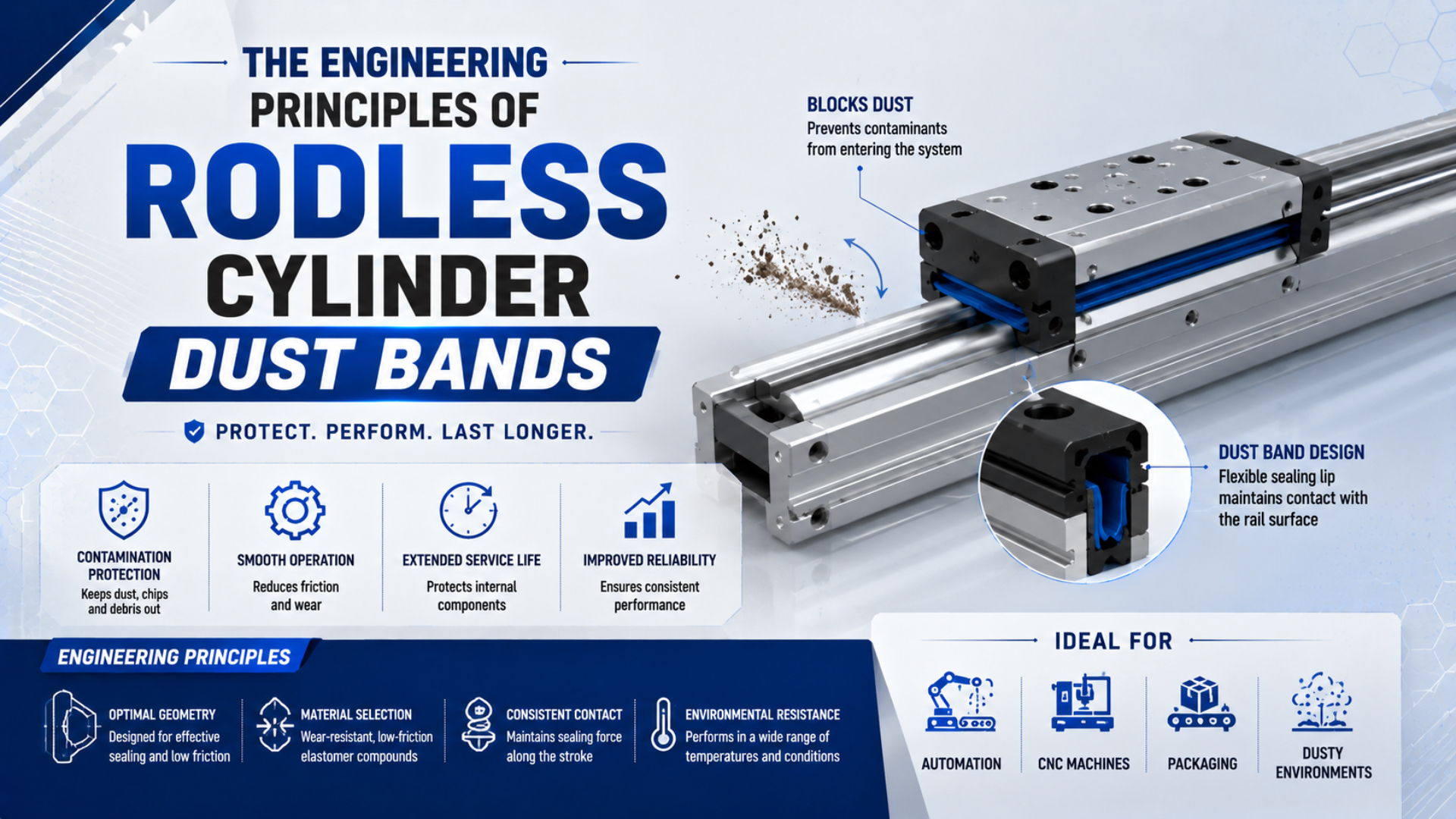
A rodless cylinder dust band is the outer strip that covers the longitudinal slot on many mechanically coupled rodless cylinders. Its main job is contamination control. It is not automatically the pressure seal, and it should not be specified as though every design uses a molded elastomer lip.
That distinction prevents expensive diagnostic mistakes. A scratched outer band can expose the slot to chips while the inner band still holds pressure. A clean outer band can also hide damage underneath. For leakage diagnosis and inner-band replacement, use the separate guide to rodless cylinder sealing band technology.
Key Takeaways
- Parker identifies separate outer and inner stainless steel bands on OSP-P cylinders from 10 to 80 mm bore.
- The outer band covers the slot; the inner band manages the pressure boundary.
- Inspect dents, kinks, trapped debris, wiper contact, end retention, and smooth reseating before ordering parts.
The Dust Band’s Actual Job
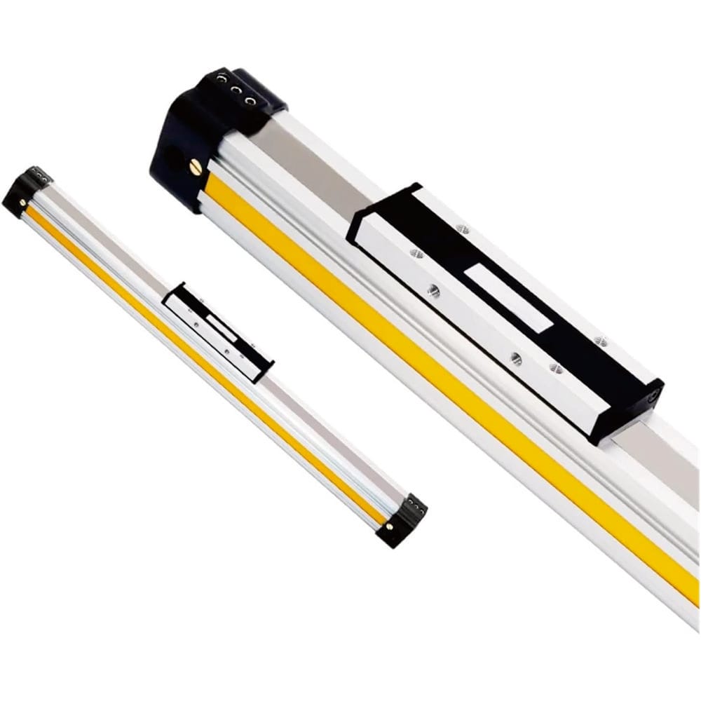
Parker’s OSP-P maintenance instructions cover cylinders from 10 to 80 mm bore and identify stainless steel bands protecting and sealing the longitudinal slot (Parker OSP-P Maintenance Instructions, retrieved 2026-07-22). Within that system, the visible outer band protects the slot while the inner band controls the pressure boundary.
Rodless cylinder dust band is the external strip that limits the entry of chips, fibers, dust, dried coolant, and handling debris into a slotted actuator. Depending on the manufacturer, the same component may be called an outer sealing band, outer cover band, dust seal band, or cover strip.
The word “sealing” creates confusion. Parker calls the visible component an outer sealing band, yet its catalog describes the outer band as a cover that prevents foreign particles from entering. The separate inner band provides the near-zero-leakage metal-to-metal pressure seal (Parker Pneumatic Rodless Cylinder Catalog, retrieved 2026-07-22).
This gives maintenance teams a useful rule: identify the failed function before naming the failed part. External contamination, visible band damage, and compressed-air leakage are three observations, not one diagnosis.
The distinction applies only to slotted, mechanically coupled cylinders. A magnetically coupled rodless cylinder has a closed tube and no longitudinal slot to cover. If the installed actuator type is uncertain, begin with the rodless pneumatic cylinder type comparison rather than ordering a band from photographs alone.
How Do the Inner Band, Outer Band, and Wipers Share the Work?
Parker numbers the OSP-P outer band as item 11, the inner band as item 17, and the external wiper as item 8 in its maintenance drawing (Parker OSP-P Maintenance Instructions, retrieved 2026-07-22). Those three identifiers represent separate interfaces with separate failure symptoms.
| Component | Primary function | Typical visible concern | What it does not prove |
|---|---|---|---|
| Inner sealing band | Closes the pressurized slot around the moving piston yoke | Kink, damaged edge, poor seating, air leak following the carriage | That the outer band is damaged |
| Outer dust or cover band | Shields the slot and inner system from external contamination | Dent, scratch, lifted edge, trapped particles, loose end | That compressed air is leaking |
| Carrier wipers | Sweep the exposed outer-band surface as the carriage moves | Torn edge, packed debris, uneven contact | That the inner pressure band needs replacement |
| Protective cover, when fitted | Adds another barrier against side entry or washdown | Bent cover, failed side seal, blocked drainage | That a standard open-profile unit is equally protected |
The pressure path sits below the visible cover. The carriage or piston yoke opens the bands only in the local transfer zone, then the bands return to their normal positions behind it. Wipers work at the moving carrier interface, where contamination is most likely to be dragged toward that opening.
SMC uses a different implementation. Its current MY1 family describes a flexible seal belt for leakage control and a dust seal band with magnetic holding force; it also offers an NBR-lined dust-band option for improved oil and peel resistance (SMC MY1 Web Catalog, retrieved 2026-07-22). Therefore, “dust band material” is a model-specific question, not a universal polyurethane-versus-PTFE selection exercise.
For the broader seal families used elsewhere in a pneumatic actuator, compare industrial cylinder seal types. A piston seal, rod wiper, carriage wiper, inner strip, and outer cover band should not be treated as interchangeable parts.
Lift, Guide, and Reseat Mechanics
The current Parker OSP-P range allows strokes up to 6,000 mm and maximum operating pressure of 8 bar, so its outer strip must remain aligned over a long slot without becoming the pressure boundary (Parker OSP-P Product Page, retrieved 2026-07-22). The carriage geometry controls the local lift and return of that strip.
The outer band needs enough longitudinal flexibility to pass through or over the carriage interface, yet enough transverse stability to lie flat over the slot. The carriage and wipers guide the temporary deflection. End clamps, screws, magnets, or other manufacturer-specific retainers control its position away from the moving zone.
Four engineering relationships matter more than a generic hardness value:
-
Band straightness and edge condition. A kink creates a local high point that the wiper must cross every cycle. A sharp dent can also direct debris below the cover.
-
Carriage guidance. Pitch, yaw, or roll at the carriage changes how the band enters the lift path. Guide wear can therefore appear as repeated band scuffing at one edge.
-
Retention without harmful slack. The strip must lie in its designed path. Parker’s RC instructions warn that the goal during inner-band assembly is to remove slack, not apply tension; excessive force can move or damage the band (Parker RC Maintenance Instructions, retrieved 2026-07-22).
-
Wiper contact and debris escape. A wiper must sweep particles without turning packed dust into an abrasive wedge. Cleaning access and protective covers may matter more than changing band material.
Pressure management is not a universal dust-band feature. Parker’s cleanroom OSP-P is a special design that creates vacuum between the inner and outer steel bands and recommends approximately 4 m3/h suction flow. That cataloged exception should not be converted into generic relief channels or vent grooves for every rodless cylinder (Parker OSP-P Maintenance Instructions, retrieved 2026-07-22).
Long-stroke band behavior also depends on the complete axis. If load moment, frame straightness, stops, or guidance are questionable, review the durability checks for 24/7 rodless-cylinder operation before assuming that a harder cover strip will solve repeat damage.
Which Damage Patterns Matter During Inspection?
Parker specifies water- and dirt-free compressed air, an 8 bar maximum pressure, and a standard temperature range from -10 to 80 degrees C for the OSP-P (Parker OSP-P Maintenance Instructions, retrieved 2026-07-22). These are series limits, while external contamination still has to be assessed at the exposed band and carriage.
Inspect the band over the full stroke with the machine safely isolated. Do not look only at the parked carriage position. A defect that repeats at one coordinate suggests a local band, slot, or frame problem; damage that travels with the carriage points more strongly toward wipers, carrier guidance, or a trapped particle.
| Observation | Likely concern | Next safe check |
|---|---|---|
| Polished line along one band edge | Wiper misalignment, carriage skew, or guide moment | Check guide play, mounting flatness, and contact symmetry |
| Local dent or crease | Impact, dropped tool, incorrect handling | Inspect the same stroke coordinate beneath the band |
| Band lifts away from the slot | Loose retention, debris underneath, damaged strip | Compare both ends and follow the series manual |
| Packed dust at a wiper | Cleaning interval or protective-cover problem | Remove loose contamination without pushing it into the slot |
| Hiss follows the carriage | Possible inner-band or carriage-interface leakage | Isolate and diagnose the pressure path separately |
| Outer band looks damaged but no leak is detected | Contamination barrier has degraded | Replace or service based on cover-band condition, not leak rate alone |
In our experience reviewing replacement requests, the most useful photographs show the nameplate, both band ends, the carriage from both sides, and the full stroke path. A close-up of one scratch rarely reveals whether the unit has an inner pressure-band problem, an outer cover problem, or a guide-alignment problem.
Harsh particles require a system response. Foundry sand, cement dust, wood fibers, welding debris, and dried washdown residue behave differently at the wiper. The mitigation may involve orientation, shielding, a protective-cover model, cleaning access, or moving the axis out of the contamination plume. The same logic appears in the guide to protecting actuators in foundry environments.
How Should You Clean, Service, or Replace a Dust Band?
Parker’s OSP-P cleaning procedure tells technicians to reduce working pressure to 2 bar, use safety glasses, and lift the outer band without creasing it before accessing the groove (Parker OSP-P Maintenance Instructions, retrieved 2026-07-22). Those details show why a generic pry-and-wipe procedure is unsafe.
Always start with the exact manufacturer, series, bore, stroke, and carriage configuration. Band edges may be sharp. Retention hardware and cover arrangements differ by size. The machine must be isolated according to the site’s energy-control procedure before hands or tools enter the carriage path.
Use this service decision sequence:
-
Identify the actuator architecture. Confirm that it is mechanically coupled and slotted, not magnetically coupled.
-
Record the hardware before removal. Photograph clamp positions, screws, band routing, carriage, wipers, and any protective cover.
-
Remove loose external contamination first. Use the method and cleaning tool specified by the manufacturer. Do not drive chips under the band with compressed-air blow-off.
-
Inspect before disturbing alignment. Mark dents, kinks, uneven polishing, lifted edges, and the stroke coordinate of each symptom.
-
Order by model and stroke. Parker’s RC instructions state that inner and outer band kits require the stroke length, while the example part numbers also vary by bore and carriage configuration (Parker RC Maintenance Instructions, retrieved 2026-07-22).
-
Follow the series torque and assembly procedure. Do not substitute a visually similar strip, improvise a groove, or apply an arbitrary tension value.
-
Verify the complete axis. Move through the stroke at controlled speed, check reseating, inspect wiper contact, and perform the manufacturer’s leakage test where required.
Do not assign a universal six-month or annual replacement interval. Condition, cycle count, stroke, contaminants, cleaning chemistry, impact, and guide alignment vary too widely. A planned inspection interval can be based on the machine’s risk and history, but the replacement decision should come from observed condition and manufacturer criteria.
The most reliable replacement request includes the nameplate, cylinder series, bore, stroke, carriage count, operating environment, photographs, and a symptom map. For the actuator-family context behind those fields, see what a rodless cylinder is and how its load path works.
Rodless Cylinder Dust Band FAQs: What Should Engineers Ask?
SMC’s current MY1 family contains five guide types and bore sizes from 10 to 100 mm, so even one product family does not share identical dust-band hardware (SMC MY1 Web Catalog, retrieved 2026-07-22). These answers separate reusable diagnostic principles from dimensions that must come from the exact series manual.
Is the dust band the pressure seal?
Not necessarily. On Parker OSP-P cylinders, the outer stainless steel band covers the slot while a separate inner band controls the pressure seal. Other manufacturers may use different names, materials, and retention methods. Identify the component from the series drawing before connecting visible outer-band damage to compressed-air leakage.
Does every rodless cylinder use a dust band?
No. A mechanically coupled rodless cylinder usually has a longitudinal slot and band system. A magnetically coupled design transfers force through a closed tube wall, so it does not need the same slot-cover arrangement. Confirm the coupling type from the model number instead of relying on the external carriage shape.
Does a scratched outer band mean the cylinder is leaking?
No. A scratch can weaken contamination protection without opening the pressure boundary. If air leakage is suspected, isolate the actuator and determine whether the hiss follows the carriage or remains at a fitting or end cap. Inspect the inner sealing path separately before ordering a complete rebuild kit.
Can a dust band be retrofitted to any rodless cylinder?
No. Band routing, slot geometry, carriage lift features, end retention, and wipers are built into the actuator design. Machining a groove or adding an improvised strip can damage the pressure system and invalidate ratings. Use a manufacturer-approved protective cover or select a series designed for the environment.
What information is needed to order a replacement dust band?
Send the manufacturer, full model code, bore, stroke, carriage count, mounting orientation, and photographs of the nameplate, both band ends, carriage, and damage. Also describe the contaminant and exact stroke location of the symptom. Band length alone does not establish profile, material, retention, or kit compatibility.
Sources and technical references
-
Parker Modular Pneumatic Linear Drive System OSP-P Maintenance Instructions, retrieved 2026-07-22. Used for component identification, operating limits, cleanroom vacuum distinction, cleaning access, and safe handling guidance.
-
Parker Pneumatic Rodless Cylinder Catalog, retrieved 2026-07-22. Used for the separate inner pressure-sealing and outer contamination-cover functions.
-
Parker OSP-P Product Page, retrieved 2026-07-22. Used for current bore, stroke, pressure, temperature, outer-band, inner-band, and wiper specifications.
-
Parker RC Series Maintenance Instructions, retrieved 2026-07-22. Used for band-kit identification, inspection cautions, assembly slack guidance, and model-specific service requirements.
-
SMC MY1 Mechanically Jointed Rodless Cylinder Web Catalog, retrieved 2026-07-22. Used for guide and bore variations, seal-belt construction, magnetic dust-band holding, and NBR-lined dust-band options.