

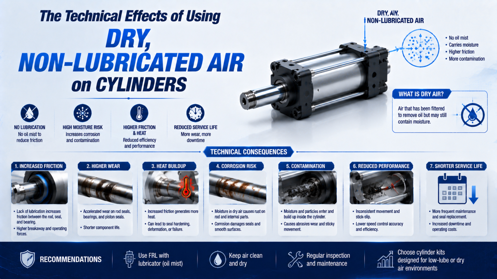
Dry compressed air does not automatically mean an unlubricated pneumatic cylinder. A cylinder described as non-lube usually contains grease applied during assembly, even though it needs no routine oil mist in its supply air. Very low water content can still disturb that retained lubrication system, but the effect is product- and duty-specific.
The engineering task is to identify four separate states: water content, oil content in the air, factory-applied internal grease, and deliberate airline lubrication. Once those are recorded, a team can compare the exact cylinder’s approved air-quality range with the application’s pressure dew point, temperature, speed, load, and cleanliness requirement.
Key Takeaways
- ISO 8573-1 classifies particles, water, and oil separately; “dry” and “oil-free” are not interchangeable.
- A non-lube cylinder can still depend on factory-applied long-life grease.
- Some manufacturers warn that ultra-dry air can reduce lubrication performance and product life.
- Establish a measured baseline before changing the dryer, oil-removal system, or lubricator state.
What Do Dry, Oil-Free, Non-Lube, and Grease-Free Actually Mean?
ISO 8573-1 uses three independent compressed-air purity dimensions: particles, water, and oil. A lower water class does not establish the oil class, and neither value states what lubricant remains inside a cylinder (ISO 8573-1, 2010). Treat each condition as a separate specification.
| Term | What it should describe | What it does not prove |
|---|---|---|
| Dry compressed air | Water content or pressure dew point at a stated location and pressure | Low oil content, cleanroom suitability, or zero internal grease |
| Oil-free compressed air | A measured total-oil limit or written oil-purity requirement | Low water content or absence of assembly grease |
| Non-lube cylinder | A cylinder intended to operate without routine airline oil under specified conditions | Dry internal sliding surfaces or approval for every dew point |
| Grease-free cylinder | A special construction with no grease in the stated boundary | Suitability for the process unless materials, particles, outgassing, and life are also qualified |
A non-lube cylinder is an actuator designed to run without routine airline oil within its stated operating envelope; it may still rely on factory-applied grease. “Oil-free compressor” is likewise a compressor description, not a point-of-use air-quality result. Ambient hydrocarbon vapour, piping residue, maintenance materials, and cross-connected branches can add oil downstream.
For a complete point-of-use specification, use the guide to ISO compressed-air quality standards.
Why Can Very Dry Air Change Cylinder Behavior?
SMC warns that ultra-dry air can deteriorate equipment lubrication characteristics and affect product reliability, and it asks users to consult the manufacturer before applying that medium (SMC C96 Cylinder Manual). That warning is a review trigger, not a universal failure prediction.
A factory-greased cylinder operates through a designed combination of lubricant, seal lip geometry, guide surfaces, roughness, contact pressure, speed, temperature, and stroke pattern. Removing water vapour does not literally remove the grease. It can, however, alter the tribological environment enough that a model qualified for ordinary dry air should not be assumed suitable for much lower pressure dew points.
Possible symptoms include higher breakaway pressure, less stable low-speed motion, rising cycle time, seal noise, or a change in leakage. These observations are not proof of grease loss. Side load, misalignment, contamination, damaged surfaces, restricted tubing, flow-control changes, and low dynamic pressure can produce the same pattern.
The useful boundary is not “wet versus dry.” It is the driest measured air condition at which the exact cylinder configuration still meets its leakage, friction, motion, and life requirements. That boundary can differ between two cylinders carrying the same seal-family label.
Do not use fixed friction, temperature-rise, wear-rate, or life-loss percentages as design values. ISO 19973-3 evaluates cylinder reliability under defined test conditions and reports life in cycles or kilometres, so a percentage without the tested model, duty, failure threshold, and baseline is not transferable (ISO 19973-3, 2015).
The Pressure-Dew-Point Boundary for Cylinders
Manufacturer limits differ. One Festo ISO cylinder specifies compressed air to ISO 8573-1 class [7:4:4], while a Parker P1D cylinder page recommends class 3.4.3 and identifies water class 4 as a +3°C pressure dew point for indoor service. These values are model examples, not universal thresholds (Festo ISO Cylinder; Parker P1D-T).
Pressure dew point is the temperature at which water would begin to condense while the air remains at the stated pressure. It is not the actual air temperature. Parker gives the example that compressed air can be at 35°C while having a pressure dew point of -40°C (Parker Clean, Dry, Oil-Free Air).
Select the dew point from two independent constraints:
- Prevent condensation and freezing. The pressure dew point must remain below the coldest expected compressed-air line, valve, actuator, and expansion zone, with a suitable margin for operating variation.
- Stay inside the component’s approved range. If a desiccant dryer takes the branch substantially below the cylinder’s stated or previously qualified condition, obtain model-specific approval or run a controlled qualification.
“Drier is always better” is poor system engineering. CAGI advises against specifying a lower dew point than the application requires because it adds capital and operating cost; it also recommends asking the end-use equipment supplier for the required dew point (CAGI Compressed Air Treatment).
Measure at the cylinder branch during representative demand. A dryer outlet certificate cannot reveal downstream leaks, bypasses, wet receivers, seasonal line temperatures, or a point-of-use pressure different from the test condition. If moisture damage is the concern, follow the pneumatic-cylinder water damage guide.
Why Doesn’t a PTFE or NBR Label Approve Dry Operation?
Parker’s pneumatic-seal catalogue states that a complete piston used with dry, oil-free air still requires the piston and tube to be prelubricated with a suitable long-life lubricant. It also limits that example design to 16 bar and 1 m/s. Both conditions matter (Parker Pneumatic Seals).
That example exposes the weakness in material-only selection. PTFE, NBR, polyurethane, and FKM are broad material families. A working sealing system also depends on the exact compound, fillers, hardness, profile, energizer, lip load, groove, counterface, surface finish, assembly grease, temperature, speed, pressure, and lateral load.
| Supplier evidence | Why it matters in dry or oil-free service |
|---|---|
| Complete cylinder and seal-kit codes | Connects the claim to the installed geometry and compound |
| Factory grease name and quantity rule | Defines the lubricant that “non-lube” operation still relies on |
| Permitted ISO 8573-1 classes or dew-point range | Identifies the tested air-quality boundary |
| Speed, pressure, temperature, stroke, and duty limits | Prevents a seal result from being detached from its motion conditions |
| Rod, tube, and guide surface specifications | Connects friction and wear to the actual counterfaces |
| Reliability or endurance evidence | States cycles or travel, test conditions, and failure criteria |
A low-friction seal can help, but it cannot correct an unapproved grease change, damaged bore, excessive side load, or unsuitable duty. For oil chemistry and seal-compound questions, see the separate guide to air lubrication and cylinder seal materials. This article keeps the narrower focus on air dryness and retained internal lubrication.
Commissioning After an Air-Quality Change
ISO 19973-3 treats pneumatic-cylinder life as cycles or kilometres and requires defined test conditions and failure thresholds (ISO 19973-3, 2015). Therefore, changing a dryer or oil-removal train should be commissioned against a measured baseline, not against an unsupported universal service interval.
Record the baseline before the change while the machine is stable. Then repeat the same measurements after the new air condition reaches the point of use:
- Identify the hardware. Capture cylinder model, bore, stroke, mounting, seal kit, options, valve, flow controls, tubing, load, and motion profile.
- Measure air quality at the use point. Record pressure dew point, pressure, temperature, particle class, oil class, sampling location, instrument, and test date.
- Measure dynamic supply conditions. Log pressure at both cylinder ports during extension and retraction, not only the regulator’s static gauge reading.
- Record motion and leakage. Compare breakaway behaviour, extend and retract times, low-speed smoothness, end cushioning, external leakage, and pressure decay where applicable.
- Inspect mechanical conditions. Check alignment, side load, rod and guide condition, mounting movement, tube routing, and contamination before blaming lubrication.
- Set acceptance and follow-up points. Define acceptable change, inspection timing, stop criteria, and the person authorised to release or reverse the change.
The most revealing measurements are often paired values. Record static regulator pressure and dynamic port pressure, dryer-outlet dew point and point-of-use dew point, commanded stroke time and measured stroke time. The gap between each pair can locate the problem before a cylinder is dismantled.
For long or flow-sensitive branches, verify the layout with the pneumatic tubing routing guide.
How Do You Separate Lubrication Trouble from Other Faults?
SMC’s C96 manual calls for a 5 µm or finer upstream filter and warns that heavy condensate can cause pneumatic equipment to malfunction (SMC C96 Cylinder Manual). Those controls matter because contamination and water can imitate or compound lubrication-related symptoms.
| Symptom after the air change | Lubrication-related possibility | Competing causes to test first | Useful comparison |
|---|---|---|---|
| Higher breakaway pressure | Lubricant-film or seal-friction change | side load, misalignment, bent rod, tightened guide, changed regulator | cylinder uncoupled from load versus connected |
| Slower extension or retraction | increased friction or leakage | restricted valve, clogged silencer, undersized tube, flow-control setting, low port pressure | port pressure and stroke time in each direction |
| Jerky low-speed motion | stick-slip at a sliding interface | meter-in control, compressibility, poor guidance, unstable load, valve hysteresis | several speeds and load states |
| New external leakage | seal wear, hardening, or disturbed grease | scratched rod, contamination, mounting distortion, incorrect seal installation | leak location and surface inspection |
| Higher surface temperature | increased sliding loss | higher cycle rate, hot ambient, cushion impact, nearby heat source | identical duty before and after change |
| Noise or dust at the rod | dry wiper interface or contamination | side load, abrasive ingress, damaged coating, washdown residue | cleaned area and alignment check |
Raising supply pressure is not a diagnosis. It can hide extra friction while increasing impact, air use, seal load, and stored energy. Compare the cylinder’s required pressure with its measured dynamic port pressure, then correct the actual restriction or load issue. The minimum operating pressure guide explains that distinction.
If wear is concentrated on one side, investigate side loading on linear actuators before changing seal material or adding oil.
What Maintenance Policy Works with Oil-Free Supply Air?
SMC permits added turbine oil for some non-lube cylinders but warns that lubrication must continue after the added oil displaces the original lubricant (SMC C96 Cylinder Manual). Starting, stopping, or changing airline oil is therefore an engineering change, not a routine adjustment.
Use condition-based maintenance tied to the qualified operating state:
- Keep the dryer, drains, filters, and oil-removal stages within their differential-pressure, dew-point, and service limits.
- Trend cylinder leakage, stroke time, breakaway behaviour, port pressure, and visible wear at consistent machine conditions.
- Inspect alignment, mounts, rod surfaces, guides, cushions, silencers, tubing, and flow controls whenever motion changes.
- Use only the specified seal kit, grease, cleaning method, and assembly quantity during a rebuild.
- After maintenance, restore the approved lubrication state and verify the same acceptance measurements used at commissioning.
Avoid fixed claims such as “inspect weekly” or “replace seals at half the normal interval” unless the equipment manufacturer or your own validated maintenance history supports them. Life should be expressed in meaningful exposure such as cycles, accumulated travel, or operating hours, with the corresponding pressure, speed, load, temperature, and air quality.
A lubricator is not a corrective device for an unexplained slow cylinder. If the cylinder was designed for non-lube service, oil can change the original grease system and affect every downstream exhaust. Diagnose the mechanical and pneumatic circuit first, then obtain written approval before changing lubrication.
What Should the Specification and Change Record Contain?
Festo’s [7:4:4] cylinder requirement demonstrates why three ISO 8573-1 fields must travel together: particle, water, and oil classes (Festo ISO Cylinder). A purchasing note that says only “dry air” or “oil-free air” leaves the cylinder’s actual operating boundary undefined.
Include these fields in an RFQ, deviation request, or dryer-change record:
- full cylinder model, bore, stroke, revision, options, seal-kit code, and mounting;
- factory grease and any restrictions on cleaning, relubrication, or lubricant mixing;
- ISO 8573-1 particle, water, and oil classes at the stated point of use;
- target and worst-case pressure dew point, line temperature, ambient temperature, and operating pressure;
- valve, tubing, fittings, flow controls, exhaust devices, and dynamic port-pressure data;
- load, speed, acceleration, cycle rate, dwell, cushioning, total daily travel, and expected life;
- cleanliness, food, pharmaceutical, silicone, outgassing, or product-contact restrictions stated separately;
- baseline results, acceptance limits, follow-up interval, stop criteria, and approval owner.
Cleanroom or food use does not become compliant merely because the airline contains no intentional oil mist. The exact cylinder, exhaust route, materials, grease, particle release, cleaning procedure, and installed process boundary still need qualification. For a focused evidence package, see the critical cleanroom cylinder specification guide.
The defensible decision is simple: use the driest air the process actually needs, but keep it inside the documented or qualified envelope of every affected pneumatic component. When that envelope is missing, create a controlled baseline-and-test plan instead of substituting a universal friction or life percentage.
Dry, Non-Lubricated Air FAQs
ISO 8573-1 separates particles, water, and oil into three purity dimensions, while Parker’s pneumatic-seal guidance still calls for long-life assembly lubrication in dry, oil-free service (ISO 8573-1; Parker Pneumatic Seals). These distinctions resolve common cylinder questions and prevent a maintenance team from treating a dryer change as a seal specification.
Does oil-free compressed air mean the cylinder contains no lubricant?
No. Oil-free describes the supplied air only when a measured oil limit and location are stated. Many non-lube cylinders still use grease applied during assembly. Parker specifically requires suitable long-life prelubrication for certain seals used with dry, oil-free air, so the cylinder documentation must define the internal lubricant boundary.
Can a standard non-lube cylinder use -40°C pressure-dew-point air?
Not by assumption. Compare the exact model’s permitted air class or dew-point range with the measured point-of-use condition. SMC warns that ultra-dry air can affect lubrication and reliability. If the manual is silent, obtain written approval or qualify the cylinder under the real load, speed, temperature, and cycle profile.
Should I raise pressure if a cylinder slows after a dryer change?
Not until the fault is identified. Record dynamic pressure at both cylinder ports, stroke time, leakage, flow-control settings, load, alignment, and point-of-use dew point. Higher pressure can mask friction or restriction while increasing impact and air use. Compare the same duty before and after the change to isolate the cause.
Can I start airline lubrication and stop it later?
Only when the cylinder and every downstream component permit the change. SMC warns that added oil can displace the original lubricant and that stopping the oil feed later may cause malfunction. Record the approved oil, feed method, branch boundary, contamination consequence, and rebuild procedure before installing or bypassing a lubricator.