

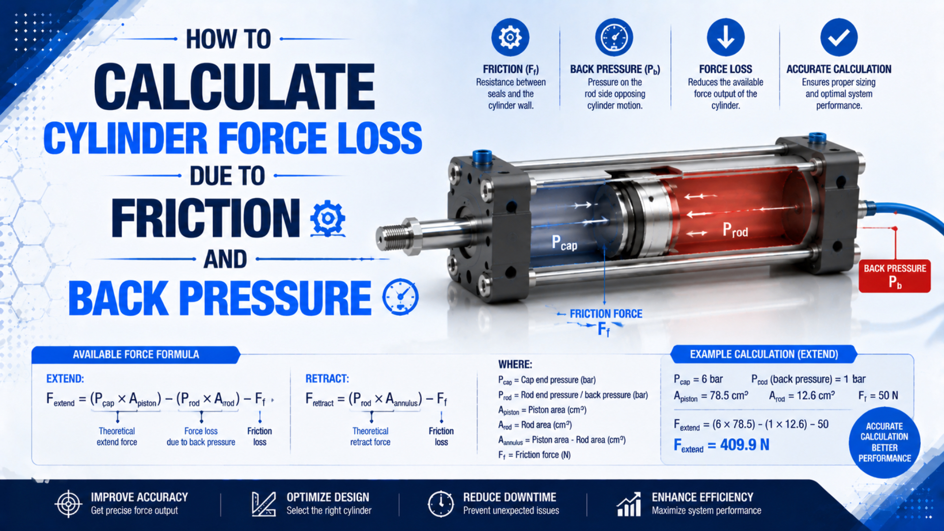
Calculate actual cylinder force from the pressure acting on both effective piston areas, then subtract measured or model-specific mechanical friction. Do not apply one generic “efficiency percentage” to every cylinder. A restricted exhaust, meter-out valve, seal design, guide load, temperature, and motion state can each change the result.
The most useful measurements are the cap-end pressure and rod-end pressure at the cylinder ports while the machine performs the required stroke. Those values reveal supply-side pressure loss and exhaust back pressure without guessing. A load cell or known external load can then expose the remaining breakaway or running friction.
Key Takeaways
- Net force uses two chamber pressures and two effective areas.
- Back pressure acts on the opposing area, not automatically on the full piston area.
- SMC says sliding resistance varies with pressure, model, and bore.
- A worked example below separates 98 N of supply shortfall, 132 N of back-pressure loss, and 100 N of measured friction.
What Does Cylinder Force Loss Actually Mean?
Cylinder force loss is the difference between a clearly defined reference force and the output available to the external load. Parker lists 251 lbf theoretical push force for a 2 inch bore at 80 psi, the direct pressure-area result (Parker, accessed 2026).
That reference must be written down. Otherwise, “20% force loss” could mean any of these:
- The difference between compressor pressure and cylinder-port pressure.
- Force opposed by pressure in the exhausting chamber.
- Seal, bearing, guide, and alignment friction.
- The difference between breakaway force and steady running force.
- A design margin that was never a physical loss.
Theoretical force is pressure multiplied by the relevant effective area before friction and opposing chamber pressure are deducted. Net pressure force is the result of both chamber pressure-area terms. Available load force is net pressure force after mechanical friction and other specified resisting forces.
Keep these values separate. A margin for acceleration, uncertainty, or service conditions belongs in the selection decision after the physical force balance. It should not be disguised as friction. For the ideal starting calculation, use the pneumatic cylinder theoretical force guide.
The phrase “force loss” becomes auditable only when the reference state, motion direction, piston position, speed, port pressures, and measurement method appear beside the result. Without those conditions, a percentage cannot be transferred safely to another machine.
How Do You Calculate Net Force From Both Cylinder Chambers?
Use pressure measured at both cylinder ports and multiply each pressure by the area it acts on. Parker defines theoretical output as ; Festo notes that exhaust back pressure creates an opposing force, especially with exhaust flow controls or a constricted exhaust (Festo, 2022).
For a single-rod, double-acting cylinder, first calculate the piston and annular areas:
Here, is full piston area, is rod-side annular area, is bore diameter, and is rod diameter. Use one consistent unit system. Pressure in MPa multiplied by area in mm² gives force in newtons because 1 MPa equals 1 N/mm².
The available extension force is:
The available retraction-force magnitude is:
is cap-end pressure, is rod-end pressure, and is friction opposing the selected direction. Use gauge pressures consistently when the atmosphere is the common reference. If an external spring, gravity component, acceleration force, or process load opposes motion, compare it with the available force after this calculation rather than hiding it inside .
How Should You Calculate Friction Loss?
Use manufacturer sliding-resistance data or measure friction on the installed axis. SMC publishes guide values at 0.5 MPa but warns that sliding resistance changes with operating pressure and can differ by model and bore (SMC, accessed 2026).
The common expression is not normally enough for pneumatic seal friction. The seal contact force is rarely known, lip seals deform under pressure, grease condition changes, and a guided actuator adds bearing resistance. Generic coefficients for NBR, polyurethane, PTFE, or FKM cannot replace data for the complete cylinder assembly.
Use one of these three methods:
- Model-specific data: Use the catalog’s typical friction or sliding-resistance value at the stated pressure, speed, lubrication, and temperature.
- No-load measurement: Run the disconnected cylinder at controlled speed, measure both port pressures, calculate net pressure force, and treat the residual as assembly friction after accounting for rod weight and fixtures.
- Loaded measurement: Measure external force with a calibrated load cell while recording both chamber pressures. Friction is the difference between net pressure force and the independently known load plus inertial and gravity terms.
Breakaway friction and running friction need separate records. Breakaway force is the peak required to start motion after rest. Running friction is measured after stable motion begins. Low-speed stick-slip can make the value oscillate rather than settle to one number; the pneumatic cylinder breakaway-force guide explains that distinction.
In our experience, a single “friction percentage” is least reliable when a machine is cold, moves slowly, carries side load, or pauses for long dwell periods. Recording the peak at breakaway and the average during a defined constant-speed window produces a more useful acceptance test.
How Much Force Does Back Pressure Remove?
Back-pressure force equals exhaust-chamber pressure multiplied by that chamber’s effective area. Parker’s rodless-cylinder threshold sensors monitor exhaust back pressure and use an operating threshold of about 6 to 9 psig, evidence that the exhausting chamber can retain measurable pressure while moving (Parker, accessed 2026).
For extension of a single-rod cylinder:
For retraction:
This area difference matters. During extension, rod-end back pressure acts on the smaller annular area. During retraction, cap-end back pressure acts on the full piston area. Subtracting back pressure from supply pressure first and multiplying the result by one area is only valid when the opposing areas are equal.
Back pressure is not always a fault. A meter-out flow control intentionally restricts exhaust to stabilize cylinder speed. The design question is whether the resulting motion remains controllable while enough net force remains for the load. A clogged silencer, undersized valve, long exhaust tube, or restrictive fitting can create unintended back pressure.
Measure at the cylinder port, not only at the valve manifold. Pressure between the cylinder and restriction is the quantity that opposes the piston. A gauge that responds too slowly can miss the peak during acceleration, so use a pressure transducer with suitable range and sample rate for a dynamic test.
Worked Example: Every Newton in the Force-Loss Budget
This example uses a 50 mm bore, 20 mm rod, 0.55 MPa cap pressure, and 0.08 MPa rod pressure during extension. Parker’s pressure-area relationship supplies the calculation basis; the assumed 100 N running-friction value is illustrative measured input, not a universal rating (Parker, accessed 2026).
The effective areas are:
Drive-side force at the measured cap pressure is:
The opposing rod-end pressure produces:
After subtracting the illustrative measured running friction:
Now compare that result with a stated reference: 0.60 MPa on the cap end, zero rod-end gauge pressure, and no friction. The reference force is 1178.1 N. The 330.1 N difference can be accounted for without a generic percentage:
| Force-loss term | Calculation | Loss |
|---|---|---|
| Drive-pressure shortfall | 98.2 N | |
| Rod-end back pressure | 131.9 N | |
| Measured running friction | Test input | 100.0 N |
| Total difference from reference | Sum of the three terms | 330.1 N |
The available force is about 28% below this particular reference. That percentage belongs only to these stated inputs. If the valve, speed, seal condition, temperature, load alignment, or port pressures change, recalculate it.
Separating Pressure Drop, Back Pressure, and Leakage
CAGI says a well-designed compressed-air system normally has no more than 10% pressure drop between compressor discharge and the point of use. That system-level benchmark does not equal cylinder back pressure or seal friction, and it should not be subtracted again after using measured cylinder-port pressure (CAGI, accessed 2026).
Use these definitions:
- Supply pressure drop is the difference between an upstream reference pressure and the active cylinder-port pressure during demand. Filters, valves, fittings, tubing, and distribution piping can contribute.
- Back pressure is pressure in the chamber that should be exhausting. It directly creates opposing force on that chamber’s effective area.
- Internal leakage is flow crossing a seal or another internal path. It can change chamber pressure, holding behavior, air use, speed, and position over time.
Do not automatically subtract a separate leakage-force percentage when both chamber pressures are already measured. If leakage lowers drive pressure or raises opposing pressure, its force effect is already inside the two pressure-area terms. Diagnose leakage separately with a documented isolation, pressure-decay, flow, or holding test.
This distinction also prevents an upstream loss from being counted twice. If the regulator reads 0.60 MPa but the cap-end transducer reads 0.55 MPa during motion, calculate force with 0.55 MPa. The 0.05 MPa shortfall is useful diagnostic information, but it should not be deducted again from the force result.
For distribution-side diagnosis, use the compressed-air pressure-drop guide or estimate the straight-run contribution with the Pressure Drop Calculator.
How Do You Measure Actual Cylinder Force on a Machine?
One Festo ISO-cylinder datasheet lists 4,712 N theoretical advance force at 6 bar and 160 N typical friction for that exact configuration. The roughly 3.4% ratio is model-specific, which is why a machine test needs the selected cylinder, real pressure, and real motion conditions (Festo, 2025).
Use the following test sequence:
- Define the test state. Record direction, piston position, payload, orientation, commanded speed, dwell time, air temperature, and whether the value is breakaway or running force.
- Install two pressure transducers. Place them as close as practical to the cap-end and rod-end ports. Confirm zero, range, units, and synchronized data acquisition.
- Measure external force independently. Use a calibrated load cell or a fixture with a known load path. Do not use motor current or valve command as a force measurement.
- Capture the complete stroke. Identify breakaway, acceleration, constant-speed travel, deceleration, cushioning, and end-of-stroke pressure separately.
- Calculate net pressure force. Apply the correct area to each synchronized pressure trace.
- Calculate the residual. During a suitable steady interval, compare net pressure force with load, gravity, and acceleration terms. The remaining opposing force is the installed friction and unmodeled resistance.
- Repeat relevant conditions. Test cold start, normal operating temperature, both directions, minimum and maximum expected payload, and the slowest critical speed.
A large cap-end pressure drop points toward supply restriction or insufficient flow. High rod-end pressure during extension points toward exhaust restriction. A high residual with normal chamber pressures points toward seal friction, guide preload, side load, contamination, or misalignment. This diagnosis is more actionable than increasing a blanket safety factor.
Use the companion guide on minimum cylinder operating pressure when the goal is to solve for required pressure rather than explain a measured force shortfall.
Cylinder Force Loss FAQs
These answers apply the two-pressure force balance rather than a universal loss allowance. ISO 15552 covers interchangeable cylinders with 32 mm to 320 mm bores and rated pressure up to 1,000 kPa, but it does not establish one friction percentage for every compliant cylinder (ISO, confirmed 2025).
What friction percentage should I use for a pneumatic cylinder?
Use the selected manufacturer’s friction or sliding-resistance data when available. Otherwise, measure breakaway and running friction under defined conditions. Festo sometimes includes a 10% allowance in preliminary sizing, but explicitly calls it approximate because lubrication, pressure, back pressure, and seal design change the result.
Should back pressure be subtracted from supply pressure?
Only when the two pressures act on equal areas. In a single-rod cylinder, extension back pressure acts on annular area while drive pressure acts on full piston area. Calculate the two pressure-area forces separately. Double-rod and some rodless arrangements may have equal nominal areas, but model geometry still needs verification.
Does internal leakage directly reduce cylinder force?
Leakage affects force when it changes chamber pressure, but it is not normally a separate fixed percentage to subtract after both port pressures are measured. It more directly affects air consumption, holding stability, speed, and pressure retention. Use an isolation, decay, or flow test to diagnose the leakage path.
Why is breakaway force different from running force?
Seals and guides can resist initial motion differently after a dwell than they do during steady travel. Pressure, lubrication, temperature, speed, side load, and seal deformation influence the gap. Record the peak at motion onset separately from the average residual during a defined constant-speed interval.
Can I calculate actual force from the regulator gauge?
Not reliably during a dynamic stroke. The regulator gauge does not show pressure loss through the valve and tubing or pressure trapped in the exhaust chamber. Measure both cylinder ports while the machine performs the required motion, then apply each pressure to the correct effective area.