

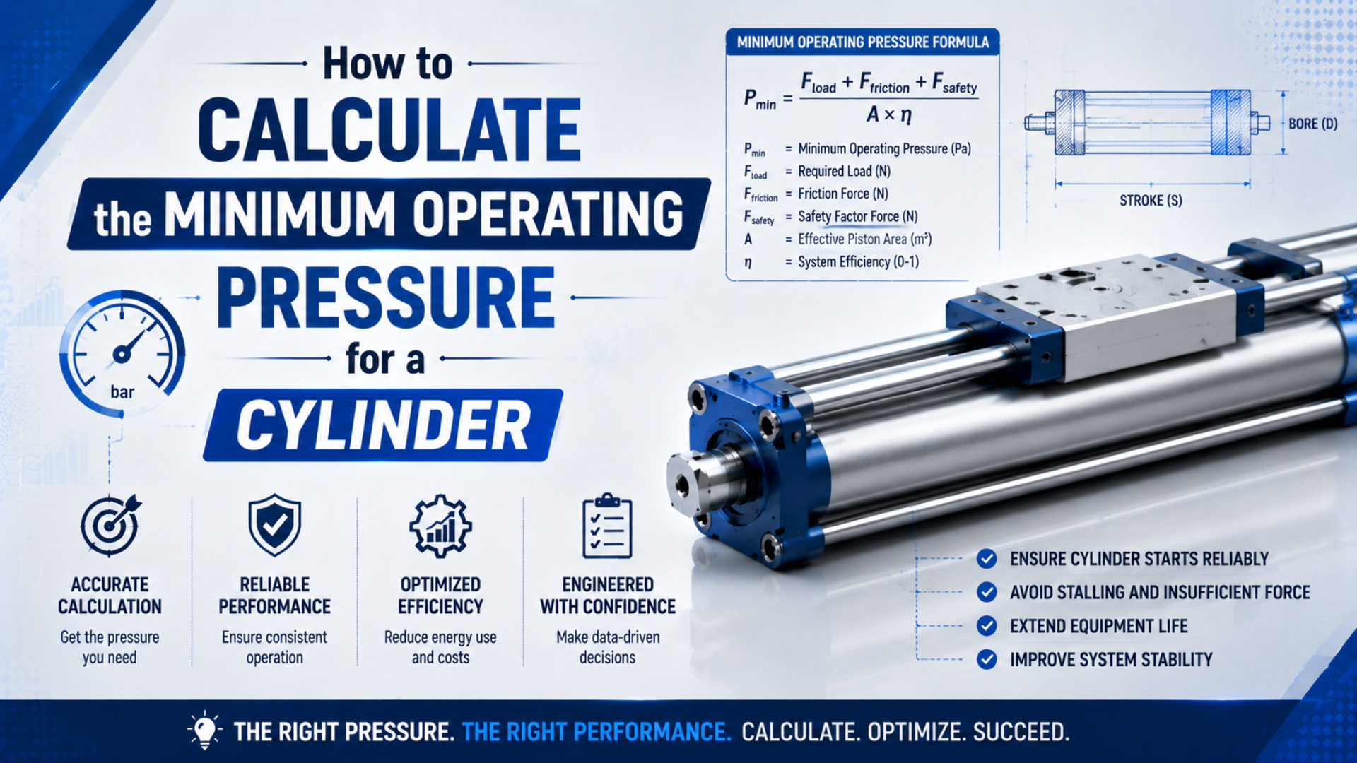
The minimum operating pressure for a cylinder is the lowest active-port pressure during motion that produces enough net force to overcome the load, acceleration, gravity, friction, springs, and pressure trapped on the exhaust side. Calculate that value for the harder stroke, compare it with the cylinder’s catalog limits, then prove it on the machine at full load and production speed.
That distinction matters. A catalog’s minimum operating pressure only describes the cylinder under the manufacturer’s stated test conditions. It is not a promise that your machine will move at that pressure. For example, SMC lists 0.05 MPa as the minimum operating pressure for its MB1 cylinder family, while also listing 1.0 MPa as the maximum operating pressure (SMC MB1 catalog, accessed July 19, 2026). Your calculated application requirement must fit between the applicable model’s limits.
Key Takeaways
- A catalog value such as 0.05 MPa is a product-specific floor, not the loaded machine requirement.
- Use cap-end area for extension and annular area for retraction.
- Include exhaust-side back pressure and measure pressure at both cylinder ports while the cylinder moves.
- Add margin from measured variation and acceptance tests, not a universal percentage.
Three Different Pressures Must Not Be Confused
SMC’s MB1 specifications give one useful boundary: 0.05 MPa minimum and 1.0 MPa maximum operating pressure for that product family (SMC MB1 catalog, accessed July 19, 2026). Neither number replaces a force balance for the installed machine. Separate these three pressure questions before calculating anything.
Catalog minimum operating pressure is the lowest pressure at which the manufacturer says a specific cylinder family will operate under stated conditions. Seal design, bore, lubrication, mounting, and test method can change it. SMC’s own selection guidance says minimum operating pressure and sliding resistance depend on model and bore, and its figures are guides rather than universal constants (SMC Basic Characteristics, accessed July 19, 2026).
Breakaway pressure is the pressure at which an installed cylinder first starts moving from rest. It includes seal stiction, guide preload, alignment error, static load, and any external binding. Our detailed guide to pneumatic cylinder breakaway force explains why this observed threshold can differ from the catalog floor.
Application minimum port pressure is the active-chamber pressure required to complete the specified motion with the real load, acceleration, opposing chamber pressure, and friction. It is the value this article calculates. The working-pressure guide covers the wider system context, including normal settings and component limits.
The governing selection rule is therefore a range, not one magic pressure:
- Calculated and tested application pressure must be above the catalog floor and observed breakaway threshold.
- It must remain below every applicable maximum rating for the cylinder, valve, regulator, tube, and fitting.
- If no reliable range remains, change the cylinder area, load, motion profile, or circuit instead of forcing the pressure upward.
How Do You Calculate Effective Area?
Pressure acts on different areas during extension and retraction. A 50 mm bore with a 20 mm rod has 1,963.5 mm² cap-end area but only 1,649.3 mm² rod-side annular area, a 16% reduction. Parker’s cylinder catalog likewise derives theoretical force from operating pressure and effective piston area (Parker P1F catalog, accessed July 19, 2026).
For a single-rod, double-acting cylinder, cap-end piston area is:
Here, is piston area, is bore diameter, and both must use compatible units. If is in millimetres, is in square millimetres.
The rod-side annular area is:
Here, is annular area and is rod diameter. Extension normally uses as the driven area and as the exhaust-side area. Retraction swaps those roles. This is why a single-rod cylinder generally needs more pressure to produce the same retract force.
Rodless and double-rod cylinders can have equal nominal working areas in both directions, but their seals, guide systems, and pressure losses still require model-specific review. For a fuller geometry treatment, see how to calculate effective piston area.
How Do You Solve Minimum Active-Port Pressure?
Use a two-port force balance, not simply load divided by area. At 0.05 MPa rod-end back pressure, a 1,649.3 mm² annular area pushes against extension with 82.5 N, a term a one-pressure calculation misses. Parker likewise derives theoretical cylinder force from operating pressure and piston area (Parker P1F catalog, accessed July 19, 2026).
For extension, solve the required cap-end pressure as:
The variables are:
- : minimum cap-end port pressure during extension.
- : all external resistance in the direction opposing motion, including process load, gravity component, spring force, guide friction, and seal friction.
- : moving mass, including tooling and payload.
- : required acceleration along the cylinder axis.
- : measured or estimated rod-end back pressure during extension.
- : rod-side annular area.
- : cap-end piston area.
Use gauge pressure consistently on both ports. With pressure in MPa and area in mm², the product gives force in newtons because 1 MPa equals 1 N/mm². NIST gives 1 psi as 6,894.757 Pa when you need to convert an imperial datasheet (NIST pressure conversions, accessed July 19, 2026). The Pressure Converter is a convenient cross-check.
For retraction, the same balance becomes:
Here, is required rod-end pressure and is cap-end back pressure. Assign signs from the intended direction: a force that assists motion is negative resistance; a force that opposes motion is positive. If the machine can move both upward and downward, calculate both cases and keep the harder one.
The back-pressure guide explains how meter-out controls, mufflers, valve exhaust capacity, and long exhaust lines can raise the opposing-port term.
For an inclined axis, the gravity component is:
Here, is 9.80665 m/s² under standard gravity and is the cylinder angle measured from horizontal (NIST SP 811 Appendix B.9, accessed July 19, 2026). Gravity contributes zero axial force at 0° and the full weight at 90°.
Worked Example: 50 mm Cylinder Lifting a Load
This example uses the 50 mm bore and 20 mm rod geometry above, standard gravity of 9.80665 m/s², and 0.05 MPa measured rod-end pressure. Those inputs produce 82.5 N of back-pressure force before process resistance is added. Treat every number below as a transparent worksheet assumption, not a catalog recommendation.
The cylinder extends vertically upward. The application inputs are:
| Input | Value | How it enters the balance |
|---|---|---|
| Moving mass | 40 kg | Gravity and acceleration |
| Required upward acceleration | 2.0 m/s² | N |
| Process resistance | 150 N | Opposes extension |
| Measured friction and binding allowance | 60 N | Opposes extension |
| Rod-end back pressure | 0.05 MPa | Acts on |
| Cap-end area | 1,963.5 mm² | Driven area |
| Rod-side area | 1,649.3 mm² | Opposing pressure area |
Weight is N. The total required cap-end force is therefore N. Required active-port pressure is:
That is about 3.90 bar or 56.5 psi. The result is far above the example cylinder family’s 0.05 MPa catalog floor, yet below its 1.0 MPa maximum. The calculation is internally consistent because every resisting force, including exhaust-side pressure, appears in the numerator.
The calculator checks the problem in the opposite direction: enter bore, rod, candidate pressure, and realistic allowances, then confirm that available force exceeds the required force. It does not replace the two-port equation when back pressure is significant.
How Should You Add Margin Without Inventing a Safety Factor?
No universal 25%, 1.5×, or 2× pressure multiplier can represent every pneumatic machine. SMC explicitly says sliding resistance varies with operating pressure, model, and bore, and its values are only guides (SMC Basic Characteristics, accessed July 19, 2026). Build margin from measured uncertainty and required acceptance performance instead.
Start with a load table, not a percentage. Record the maximum payload, tooling mass, process force, spring force, intended acceleration, and worst mounting angle. Then identify which values are measured, which come from drawings, and which are conservative assumptions. A hidden assumption is more dangerous than a visibly small margin.
In our experience, friction deserves its own line because it changes after seal replacement, guide adjustment, contamination, or misalignment. Measure breakaway pressure in both directions with the load safely controlled. If the cylinder is already installed, compare that result with the unloaded value. The difference can reveal external binding that a catalog friction percentage would miss.
Next, test variation. Use the lowest credible supply condition, coldest start, heaviest permitted load, and fastest specified cycle. Margin is the difference between the pressure that passes every acceptance test and the pressure at which timing, force, or stroke completion begins to fail. Document both numbers. Don’t exceed a component rating to create margin.
Safety-related holding, clamping, or suspended-load functions need a separate risk assessment. ISO 4414:2010 covers pneumatic-system safety requirements across design, installation, operation, and maintenance, and ISO confirmed the standard in 2021 (ISO 4414, accessed July 19, 2026). A calculated pressure alone is not a safety function.
Why Can Regulator Pressure Be Higher Than Cylinder-Port Pressure?
CAGI recommends limiting pressure drop from compressor discharge to the point of use to no more than 10% in a well-designed system (CAGI Pressure Drop Technical Brief, accessed July 19, 2026). A regulator gauge can therefore look adequate while the active cylinder port falls below the calculated minimum during acceleration.
The critical pressure is at the cylinder port while air is flowing. Static regulator pressure before motion does not reveal losses through undersized valves, fittings, tubing, quick exhausts, mufflers, filters, or long distribution lines. Measure cap-end and rod-end pressure simultaneously if the motion is marginal. One trace shows the driving pressure; the other shows back pressure.
Once measured dynamic drop is known, the minimum regulator setting is:
Here, is the regulator’s loaded setting, is the calculated active-port requirement, and is the worst observed drop from regulator to active port. If the worked example loses 0.06 MPa during acceleration, the loaded regulator setting must provide at least 0.45 MPa before test margin is considered.
CAGI advises fixing restrictions rather than automatically raising system pressure. Check the Pressure Drop Calculator when pipe or tube length, inside diameter, and flow are known. A local receiver or larger valve may solve a short peak-demand problem with less energy and less stress than increasing plant-wide pressure.
Field Verification at Cold Start and Production Speed
SMC lists piston-speed ranges of 50 to 1,000 mm/s for several smaller MB1 bores and 50 to 700 mm/s for 100 and 125 mm versions (SMC MB1 catalog, accessed July 19, 2026). Speed limits and pressure needs are model-specific, so verify the exact cylinder under real cycle conditions.
Use a controlled test sequence:
- Confirm cylinder, valve, regulator, tubing, fitting, and accessory pressure ratings.
- Fit suitable pressure transducers close to both cylinder ports. Record regulator pressure as a third channel when possible.
- Secure the load and start with a pressure already known to be safe for the equipment. Never use a suspended load as the only restraint.
- Run cold-start cycles at the maximum permitted payload and intended acceleration.
- Record active-port pressure, exhaust-side back pressure, stroke time, end position, and any hesitation.
- Repeat at normal temperature and production cycle rate. Include simultaneous consumers that can pull down the branch supply.
- Establish the lowest setting that passes the acceptance criteria, then add only the documented operating margin.
We’ve found that a slow manual jog can hide the actual problem. Acceleration force is small, flow demand is low, and exhaust back pressure may never reach its production value. If a cylinder works during setup but stalls in automatic mode, compare the pressure traces before changing the cylinder. The load-weight guide explains why cylinder acceleration changes with payload.
Use calibrated instruments appropriate to the acceptance tolerance and measurement range. The old article’s cited ISO link was not a pressure-gauge standard, so this procedure does not assign a made-up universal accuracy class. Record instrument identification, range, calibration status, sample rate, sensor location, load state, temperature, and valve command with the test result.
What Should You Do When the Required Pressure Is Too High?
The MB1 example’s 1.0 MPa maximum shows why pressure cannot be increased indefinitely (SMC MB1 catalog, accessed July 19, 2026). If the calculated or tested requirement approaches any component limit, change the force balance or flow path. Do not treat the rating as a normal target.
Use this order of attack:
- Reduce binding and friction. Correct alignment, side load, guide preload, damaged seals, contamination, and worn bearings.
- Reduce opposing pressure. Check meter-out controls, mufflers, exhaust plumbing, and valve exhaust capacity.
- Reduce pressure drop. Increase valve or tubing capacity, remove restrictive fittings, or shorten the flow path.
- Change the motion profile. Lower acceleration, soften the start, or extend cycle time when the process permits it.
- Increase effective area. Select a larger bore or a balanced actuator architecture after checking space, air use, rod strength, and cushioning.
- Reduce or counterbalance the load. Springs, counterweights, or mechanical assistance can remove force from the pneumatic axis.
A larger bore lowers required pressure but raises air volume and peak flow demand. That can recreate the problem as dynamic pressure loss. Recalculate force, flow, stroke time, cushioning energy, mounting loads, and air consumption together. Minimum pressure is one part of cylinder sizing, not the whole selection.
Conclusion: What Pressure Should You Set?
Set the regulator so the active cylinder port stays above the tested minimum during the hardest stroke while all components remain below their ratings. In the worked example, 0.390 MPa at the cap-end plus 0.06 MPa measured loss set a 0.45 MPa baseline, with units checked against NIST pressure conversions.
The defensible answer comes from five records: effective area, resisting-force table, acceleration target, two-port dynamic pressure trace, and acceptance-test result. Keep the catalog minimum as a boundary check. Keep breakaway pressure as a diagnostic. Use the application minimum port pressure as the operating calculation, then review it whenever the load, speed, circuit, mounting, environment, or cylinder condition changes.
Pneumatic Cylinder FAQs: What Should Buyers Ask?
SMC’s published 0.05 MPa MB1 minimum and 1.0 MPa maximum illustrate the size of the possible operating window, but the installed application determines the usable part of that range (SMC MB1 catalog, accessed July 19, 2026). These answers address the field questions that most often change the calculation.
Is catalog minimum pressure enough for a loaded cylinder?
No. Catalog minimum pressure is a model-specific test value, not the pressure required to move your payload. Calculate active-port pressure from load, gravity, acceleration, friction, spring force, and exhaust-side pressure. Then test the installed machine at cold start, maximum load, and production speed while staying within every component rating.
Should I use extend area or retract area?
Use cap-end piston area for extension and rod-side annular area for retraction on a single-rod cylinder. Also include pressure acting on the opposite area. Because the rod reduces retract area, equal port pressures do not normally produce equal push and pull force. Calculate both strokes and design for the harder case.
Does temperature directly change cylinder force at the same port pressure?
Not in the basic pressure-area equation: at the same measured port pressure and effective area, theoretical pressure force is unchanged. Temperature can still alter seal friction, lubricant behavior, leakage, material clearances, and chamber filling or exhaust response. Test at the application’s temperature limits instead of applying an air-density percentage to force.
Why does the cylinder fail even when regulator pressure matches the calculation?
The regulator gauge may show static upstream pressure, while the active cylinder port drops during acceleration. Valve, tubing, fittings, filters, and flow controls create losses; the exhaust side can also build back pressure. Measure both cylinder ports during motion, then use the actual pressure difference in the force balance.
How often should minimum operating pressure be recalculated?
There is no defensible universal annual interval. Recalculate and retest after changes to load, speed, acceleration, bore, rod, valve, tubing, flow controls, mounting, guidance, temperature range, or safety requirements. Also investigate when breakaway pressure, cycle time, port-pressure traces, or stroke completion drift from the accepted baseline.
Sources and technical references
- SMC MB1 air cylinder catalog, product-specific operating pressure and speed limits.
- SMC Basic Characteristics: Air Cylinders, model and bore dependence of sliding resistance and minimum pressure.
- Parker P1F ISO Cylinder Technical Catalogue, theoretical force, pressure, and effective-area relationships.
- CAGI Pressure Drop Technical Brief, pressure-drop guidance and restriction correction.
- NIST Pressure and Gas Flow Unit Conversions, authoritative pressure conversions.
- NIST SP 811 Appendix B.9, standard gravity and unit factors.
- ISO 4414:2010, pneumatic-system safety requirements.
- AutomationDirect: How to Select a Pneumatic Cylinder, selection video.