

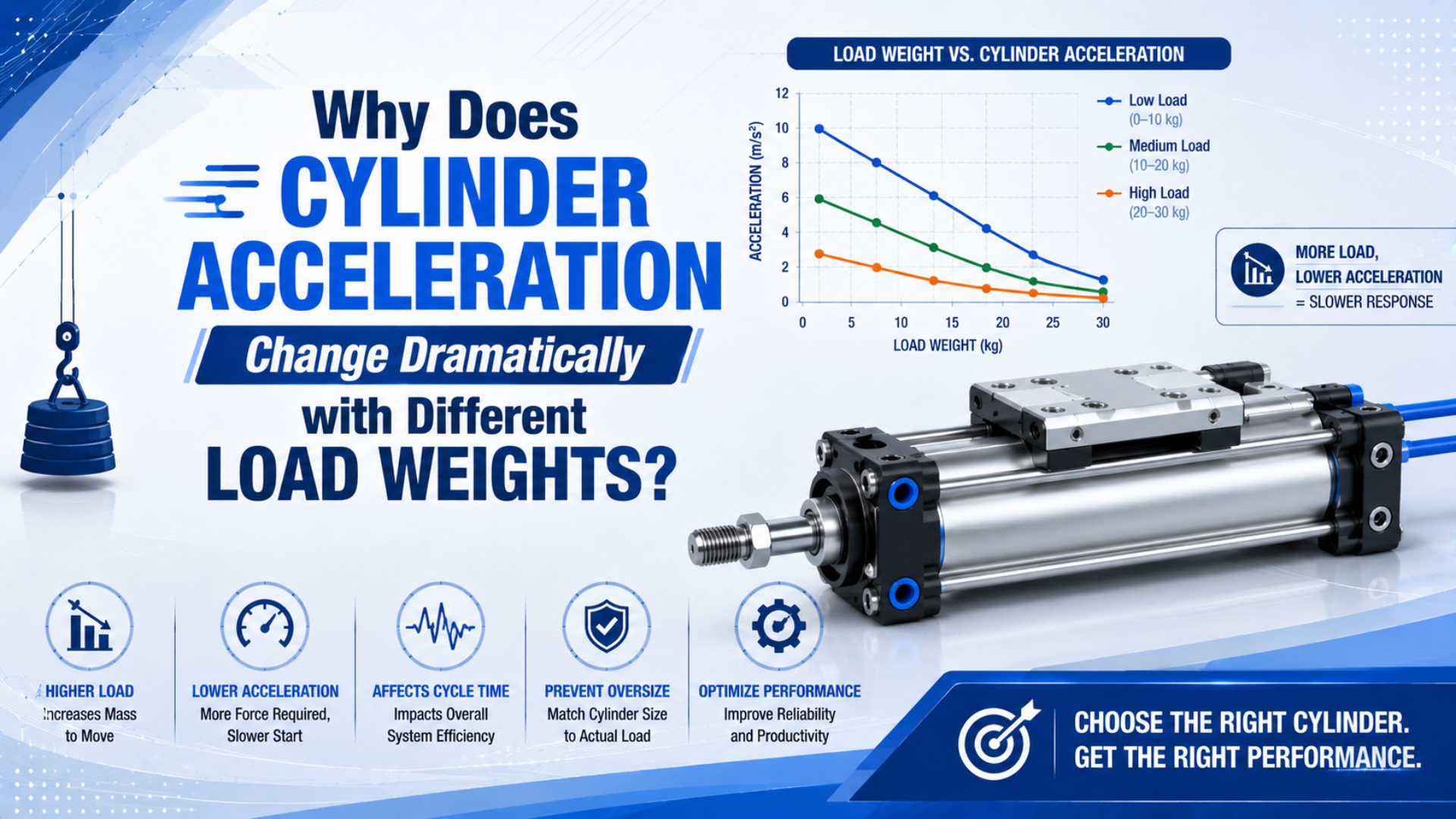
Cylinder acceleration changes with load because acceleration equals the instantaneous net force divided by the total moving mass. A heavier payload increases that mass and may also add gravity, guide friction, or process resistance. Meanwhile, the cylinder’s driving force changes as its two chamber pressures rise and fall during the stroke.
That is why the regulator setting alone can’t predict motion. SMC’s drive-system charts compare stroke time and end velocity at load factors of 10%, 30%, 50%, and 70% under tightly defined pressure, piping, orientation, valve, and speed-controller conditions (SMC drive-system technical data, accessed July 19, 2026).
Key Takeaways
- Acceleration depends on net dynamic force, not theoretical cylinder thrust alone.
- SMC generally limits dynamic selection load factor to 50% or less, with lower factors for high speed.
- Measure pressure at both cylinder ports during motion.
- Flow controls set a restriction; feedback control compensates for changing loads.
From our analysis of this dynamic force balance, the practical question isn’t “How much weight can the cylinder move?” It is “How much force margin remains at each point in the stroke while air is actually flowing?” A cylinder may pass a static force check yet accelerate slowly because the inlet pressure collapses, exhaust back pressure rises, or breakaway friction consumes the margin.
What Actually Determines Cylinder Acceleration?
Newton’s second law relates acceleration to net force and mass. SMC adds a pneumatic reality: seal and bearing resistance must be subtracted, and exhaust pressure creates another opposing force during operation (NASA; SMC model-selection data, accessed July 19, 2026).
Net dynamic force is the driving force from one chamber minus the force produced by pressure in the opposite chamber and every mechanical load acting along the motion axis. For extension of a double-acting, single-rod cylinder, a useful force balance is:
The corresponding acceleration is:
where:
- is instantaneous cap-end pressure during motion;
- is instantaneous rod-end pressure during motion;
- is full piston area;
- is the rod-side annular area;
- includes cylinder, guide, seal, and sliding resistance along the axis;
- is the component of gravity opposing the commanded direction;
- is any cutting, pressing, clamping, or contact force;
- is the payload plus every moving carriage, rod, fixture, and tool reflected to the axis.
The piston areas are:
Here, is bore diameter and is rod diameter. Parker confirms that extension uses the full bore area while retraction uses the piston area minus rod area. Its dynamic selection guidance also asks for required force, desired speed, and pressure maintained under flowing conditions, not a static gauge reading (Parker engineering data, accessed July 19, 2026).
This equation is a first-pass engineering model, not a promise of constant acceleration. The chamber pressures change with piston position, valve opening, tube volume, supply pressure, and exhaust restriction. Seal friction can also change at breakaway. The result is a time-varying , so real acceleration changes throughout the stroke.
Why Does the Same Supply Pressure Produce Different Motion?
SMC’s published drive charts hold supply pressure at 0.5 MPa yet still show separate stroke-time and end-velocity curves for 10%, 30%, 50%, and 70% load factors. The charts also fix piping length, orientation, valve, silencer, and meter-out controller, proving that pressure alone doesn’t define motion (SMC, 2026).
The regulator may read the same before every cycle, but the pressure at the cylinder port falls when air starts flowing. A heavier load can keep piston speed low while the inlet chamber fills, so pressure rises differently than it does with a light load. At the same time, exhaust-side pressure depends on the meter-out restriction, valve path, silencer, tubing, and piston velocity.
This creates three different pressure values that shouldn’t be confused:
| Pressure value | What it tells you | What it cannot prove |
|---|---|---|
| Static regulator pressure | Available setting before or between motions | Pressure maintained at the cylinder during acceleration |
| Inlet-port dynamic pressure | Actual driving-side pressure during the stroke | Net force without the opposite chamber pressure |
| Exhaust-port dynamic pressure | Back pressure resisting the piston | Mechanical friction or external process load |
Two payloads can therefore see different net force even when the regulator, valve command, and flow-control setting never change. The lighter payload may accelerate quickly enough to create higher exhaust back pressure. The heavier payload may move slowly while the driving chamber builds pressure. Neither condition is represented by one static gauge reading.
For static force fundamentals, see Understanding the Force Factor in Pneumatic Cylinder Selection. Use the present article when the problem is motion after the valve switches, not merely whether the cylinder can move the load at all.
How Do Mass, Gravity, and Friction Change the Force Budget?
SMC recommends a load factor of 0.5 or less for general dynamic vertical and horizontal motion, and says to reduce it further when high-speed operation is required. Its separate guided-horizontal allowance shows why orientation and load path matter as much as payload mass (SMC model-selection data, 2026).
Equivalent moving mass is the total inertia accelerated by the cylinder. It includes the payload, tooling, carriage, moving guide elements, piston rod, and other linked parts. Counting only the product weight understates the mass in many pick-and-place, transfer, and guided-slide applications.
Gravity changes the force budget according to direction:
- During an upward stroke, payload weight opposes the cylinder.
- During a downward stroke, gravity can become an overrunning force that tries to pull the actuator faster.
- During horizontal travel, gravity normally acts through the guide reaction rather than directly along the motion axis, but it can increase guide friction.
- On an incline, use the gravity component parallel to the axis.
Friction also needs the correct boundary. Cylinder seal friction doesn’t automatically increase in direct proportion to external payload. Guide friction may increase with payload, misalignment, moment load, contamination, or preload. Parker lists misalignment and the difference between static and kinetic friction as causes of erratic cylinder motion (Parker cylinder troubleshooting, accessed July 19, 2026).
If motion hesitates and then jumps, compare this explanation with What Is Breakaway Force in Pneumatic Cylinders?. If load moment or side force changes with product weight, audit the guide separately using How to Mitigate Side Load Issues in Linear Cylinder Applications.
Flow Capacity and Back Pressure Set the Motion Envelope
Parker’s dynamic selection graph requires force, desired speed, and pressure maintained under flowing conditions. SMC’s speed charts additionally specify tube length, valve, silencer, and meter-out controller. Together, these references show that cylinder motion belongs to the whole air path, not the actuator alone (Parker; SMC, 2026).
The inlet path must deliver enough mass flow to raise chamber pressure while chamber volume is expanding. The exhaust path must release air without creating more back pressure than the force budget allows. A restrictive valve, undersized tube, long hose, clogged silencer, or over-closed speed controller can change both pressure histories.
Meter-out control is widely used because exhaust restriction maintains back pressure and can make ordinary cylinder motion more stable. It still doesn’t command a fixed acceleration. Parker warns that excessive back pressure from over-adjusted speed controls can accelerate seal wear, while its troubleshooting guidance recommends speed control to manage erratic motion caused by static-versus-kinetic friction.
Use our guide to pneumatic flow-control valve types to distinguish a manual restriction from pressure-compensated or proportional control. For a known target stroke time, the Cylinder Flow Requirement Calculator is a useful next step after the force margin has been checked.
A Worked Comparison for Two Load Weights
Newton’s second law gives an exact ideal ratio: if net force stays constant while equivalent moving mass doubles, acceleration halves. Real pneumatic systems deviate because the net force also changes with chamber pressure, friction, gravity, and process resistance (NASA Glenn Research Center, accessed July 19, 2026).
Assume an illustrative horizontal axis has an instantaneous net force of . Compare a light configuration with equivalent moving mass and a heavier configuration with :
The example demonstrates the mass relationship only. It is not a recommended machine acceleration. In a real cylinder, the 400 N net force must be calculated from measured chamber pressures and actual losses at the instant being analyzed.
Now suppose the heavier payload also adds guide friction or upward gravitational resistance. Its falls as rises, so acceleration decreases by more than the simple one-half ratio. Conversely, an overrunning vertical load can accelerate the piston faster than expected unless the exhaust side maintains adequate control.
This is why a universal table that assigns one speed to each payload and bore is unsafe. Stroke length, valve conductance, tube size, orientation, cushion setting, and pressure under flow must accompany any numerical result.
How Should You Stabilize Motion Across Variable Loads?
SMC’s smooth-cylinder guidance uses meter-out control and notes that combining it with meter-in control can reduce stick-slip. Festo describes a different level of control: sensors, proportional valves, and closed-loop logic that adapt pressure and flow to changing process requirements in real time (SMC CP96; Festo Controlled Pneumatics, accessed July 19, 2026).
Choose the correction that matches the failure mode:
| Observed behavior | Likely mechanism | First checks | Possible correction |
|---|---|---|---|
| Heavy load starts late | Low breakaway force margin, inlet pressure drop | Both port pressures, seal/guide friction | More force margin, better supply path, alignment repair |
| Light load launches too fast | Excess force margin, open exhaust path | Meter-out setting, valve and exhaust path | Meter-out adjustment, softer pressure strategy, controlled valve |
| Speed changes after maintenance | Changed restriction, tubing, silencer, lubrication, or alignment | Compare settings and pressure traces | Restore documented setup and verify full stroke |
| Downward load runs away | Gravity assists motion and exhaust control is weak | Load direction, exhaust pressure, valve fail state | Meter-out or load-control circuit designed for the application |
| Speed must stay consistent across recipes | Open-loop restriction cannot compensate enough | Position, pressure, flow, and load feedback needs | Proportional or closed-loop pneumatic control, or electric axis review |
Increasing bore size is only one option. It raises theoretical force, but it also increases chamber area and air volume. The existing valve and tubing may then take longer to fill the chamber. Raising pressure is also bounded by component ratings, machine risk controls, and the available flowing pressure.
For vertical applications, use A Guide to Selecting Cylinders for Vertical Lifting Applications and define the safe state during air loss. A normal flow control is not automatically a load-holding or personnel-safety device.
The most reliable variable-load solution often separates two goals: keep enough pressure margin to move the heaviest load, then control airflow or motion so the lightest load doesn’t launch. Trying to solve both goals with one oversized cylinder and one fixed needle setting can move the instability rather than remove it.
What Should You Measure Before Resizing the Cylinder?
SMC’s published speed curves lock down pressure at 0.5 MPa, use defined tube lengths from 1 to 3 m, and specify vertical orientation plus meter-out control. If your installation differs, collect its actual inputs before borrowing a catalog curve (SMC drive-system technical data, 2026).
Record at least:
- Payload mass for every recipe, plus tooling and moving carriage mass.
- Stroke, orientation, center of gravity, guide type, and moment loads.
- Cap-end and rod-end pressure traces during the complete stroke.
- Position versus time, preferably with enough sampling rate to estimate velocity and acceleration.
- Valve model, flow direction, silencer, fittings, tube inside diameter, and tube length.
- Static regulator pressure and minimum upstream pressure while other consumers operate.
- Breakaway behavior, running friction, process contact force, and temperature.
- End velocity, cushion entry velocity, impact behavior, and required stopping distance.
- Required cycle time, acceptable variation, and fault response.
Parker recommends checking pressure at the cylinder when a load fails to move and lists undersizing, misalignment, and friction changes among troubleshooting causes. Those checks are more informative than increasing regulator pressure without knowing where the force margin is being lost.
If the load reaches the end cap at higher speed, verify kinetic energy as well as acceleration. SMC requires checking cushion absorption capacity against load mass and speed, while Parker includes piston and rod weight when evaluating stopping energy. Use the Cylinder Cushion Energy Calculator for a preliminary check, then apply the selected cylinder’s catalog limits.
Cylinder Acceleration FAQs
SMC generally recommends a dynamic load factor of 50% or less and a still lower factor when high speed is required. That is a selection guide, not a universal acceleration guarantee. These answers separate the force, flow, friction, and control questions that must be verified for each machine (SMC, 2026).
If I double the load, will cylinder acceleration always be cut in half?
Only if instantaneous net force remains unchanged. In a real pneumatic system, the heavier load can alter guide friction, gravity force, piston speed, inlet pressure buildup, and exhaust back pressure. Doubling equivalent moving mass therefore gives a useful ideal ratio, but measured acceleration may fall by more or less than one-half.
Why can a light load be harder to control than a heavy load?
A light load leaves more force margin, so it can break away and accelerate abruptly. That may raise end velocity, impact energy, and exhaust back pressure. A heavier load often starts more slowly, but it isn’t inherently more accurate or safer. Both extremes must pass motion and stopping-energy checks.
Will increasing the cylinder bore restore the original acceleration?
Not automatically. A larger bore increases theoretical force at the same pressure, but it also increases chamber volume and required airflow. If the valve, fittings, tubing, or supply cannot maintain pressure during flow, the larger cylinder may still accelerate slowly. Recheck force margin and flow capacity together.
Can a meter-out valve keep speed constant for every load?
A meter-out valve can improve stability by restricting exhaust and maintaining back pressure, but it is an open-loop setting. Large payload changes can still alter acceleration and travel time. When speed must remain within a tight band across recipes, evaluate pressure-compensated flow control, proportional valves, feedback control, or electric motion.
What is the fastest way to diagnose load-dependent acceleration?
Measure both cylinder-port pressures and position versus time for the lightest and heaviest loads. Then compare breakaway, pressure buildup, exhaust back pressure, peak velocity, and stopping behavior. A static regulator gauge cannot show which part of the dynamic force budget changed during the stroke.
Sources and technical references
- NASA Glenn Research Center, Newton’s Laws of Motion, net force, mass, and acceleration relationship. Retrieved July 19, 2026.
- SMC Air Cylinders Model Selection, load-factor guidance, opposing forces, cushion checks, and high-speed selection. Retrieved July 19, 2026.
- SMC Air Cylinder Drive System Technical Data, full-stroke time and end-velocity curves under defined load, pressure, piping, orientation, and valve conditions. Retrieved July 19, 2026.
- SMC CP96 Smooth Cylinder, meter-out, meter-in, stick-slip, and vertical-load circuit guidance. Retrieved July 19, 2026.
- Parker Pneumatic Actuator Engineering Data, piston areas, dynamic selection, maintained pressure, speed, and cushioning. Retrieved July 19, 2026.
- Parker Hydraulic and Pneumatic Cylinder Catalog, cylinder troubleshooting, friction, alignment, pressure, and speed-control cautions. Retrieved July 19, 2026.
- Festo Controlled Pneumatics, feedback-based pressure, flow, and motion control. Retrieved July 19, 2026.
- AutomationDirect, How to Select a Pneumatic Cylinder, cylinder-selection video uploaded April 16, 2021. Retrieved July 19, 2026.