

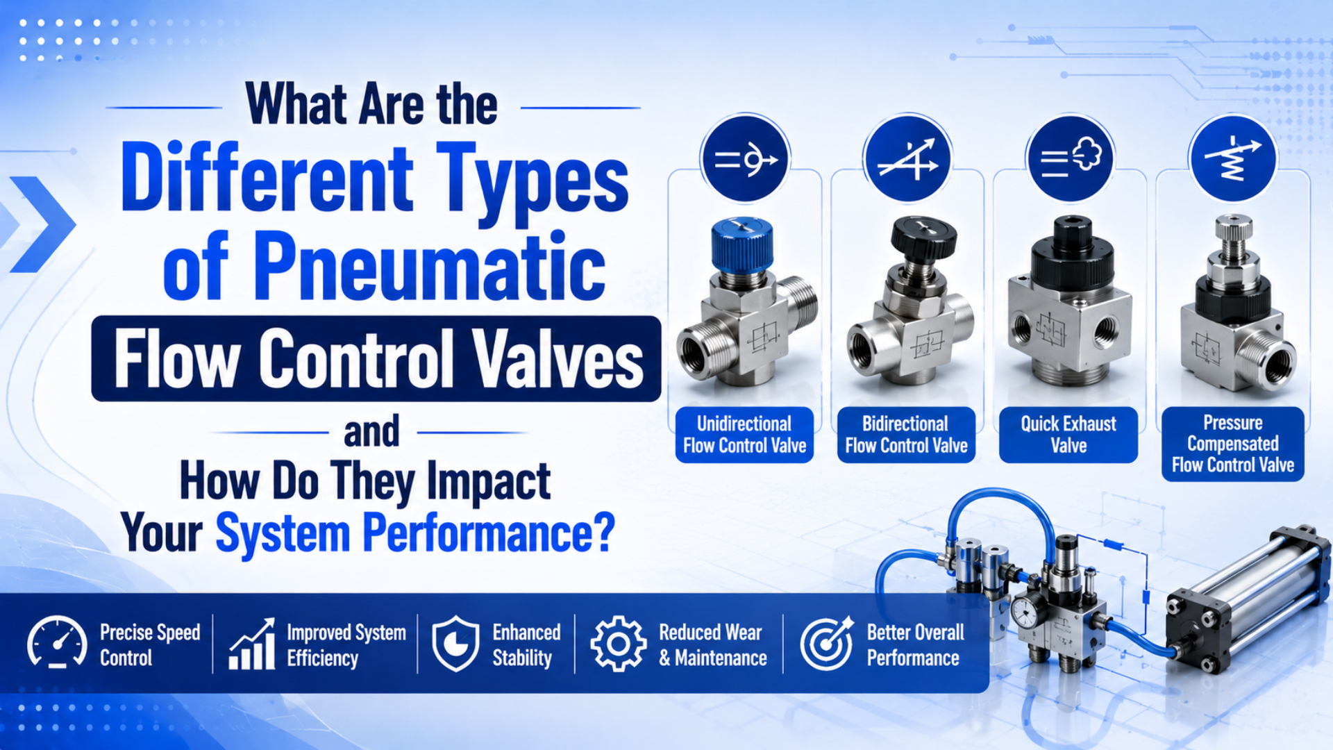
Pneumatic flow control valves affect system performance by controlling how fast compressed air fills and exhausts an actuator. For cylinder speed, the useful split is simple: pressure creates force, while flow creates motion speed. SMC states cylinder speed is a function of airflow and gives the relation s = 28.8q / A for speed, flow, and piston area (SMC, 2026).
The right valve type depends on what you are trying to control. A needle-style speed controller is usually enough for fixed cylinder speed. A check valve gives free flow in one direction and restricted flow in the other. A proportional valve belongs in PLC-controlled speed profiles. A servo-pneumatic system needs feedback, not just a fancier valve.
Key Takeaways
- SMC ties cylinder speed to airflow, not pressure alone.
- CAGI recommends no more than 10% pressure drop from compressor discharge to point of use.
- Parker’s 80 psi valve-sizing example calculates Cv 1.06 for a specific 3-1/4 inch bore, 12 inch stroke, and 1 second move.
- Proportional valves need signal, flow range, tuning, and feedback context.
The field mistake I see most often is treating “flow control valve” as one product family. In practice, the buyer is choosing a control method: fixed manual restriction, one-way cylinder speed control, directional switching, analog proportional metering, or closed-loop servo-pneumatic positioning.
Pneumatic Flow Control Valve Types at a Glance
Flow control valve selection starts with the job, not the catalog name. AutomationDirect describes 2-port, 2-position valves as simple on/off devices, while SMC says cylinder speed is usually controlled at the exhaust port with a meter-out flow control or needle valve (AutomationDirect, 2026; SMC, 2026).
Use this first cut before looking at thread size, tube OD, or price:
| Valve type | Main job | Best use | Watch point |
|---|---|---|---|
| Needle valve | Manual restriction | Fine fixed-speed adjustment | Can be too slow for high-flow axes |
| One-way flow control | Meter-in or meter-out speed control | Cylinder extend and retract tuning | Direction matters |
| Ball or shut-off valve | Isolation | Lockout, maintenance, branch isolation | Not a precision speed control |
| Directional valve | Route air to ports | Extend, retract, exhaust, stop logic | Port and way count drive behavior |
| Proportional flow valve | Variable electronic metering | PLC speed profiles and recipe changes | Needs signal scaling and tuning |
| Servo-pneumatic assembly | Closed-loop motion | Mid-stroke positioning or profiles | Needs valve, feedback, and controller |
A rodless cylinder makes the choice more visible because long strokes and external carriage loads expose weak flow paths. The valve may look correct on paper, but small fittings, long tubes, restricted exhaust, or poor meter-out orientation can still make the carriage crawl, jump, or slam.
For the proportional-only angle, use the companion article on how proportional flow control valves work in rodless cylinder systems. This page stays broader: it compares valve types and selection tradeoffs.
How Do Meter-Out and Meter-In Flow Controls Affect Cylinder Speed?
Meter-out control affects speed by restricting exhaust air and creating back pressure. SMC calls exhaust-side control the most common industry practice, and AutomationDirect says two flow controls on a double-acting cylinder allow independent extension and retraction speed adjustment (SMC, 2026; AutomationDirect, 2026).
Meter-out is usually the safer starting point for double-acting pneumatic cylinders because the exhausting side resists runaway motion. It gives the piston or rodless carriage a pneumatic cushion of back pressure. That matters when the load helps the motion, friction changes, or the cylinder is mounted vertically.
Meter-in restricts supply air. It can work on single-acting cylinders, blow-off circuits, and slow, stable loads. It is less forgiving on double-acting motion because the exhaust side can empty freely. If the load pulls the actuator, the cylinder may move faster than the supply restriction suggests.
In our experience, speed complaints often disappear after someone flips a misoriented speed controller. The part was not defective. The check direction was wrong, so the restriction acted on the wrong side of the cylinder stroke.
For cylinder speed calculation, keep this relationship in mind:
cylinder speed depends on available airflow / effective piston areaThat is only a first check. Real speed also depends on port size, tube ID, mufflers, cushion needles, valve Cv, moving mass, seal friction, and point-of-use pressure during motion.
When Should You Use Needle, Check, Shut-Off, or Directional Valves?
Manual valve choice depends on whether the circuit needs restriction, one-way bypass, isolation, or air routing. AutomationDirect says a 2-port, 2-position valve gives simple on/off function, while flow controls are typically used when a correctly sized cylinder still strokes too quickly (AutomationDirect, 2026; AutomationDirect FAQ, 2026).
Choose a needle valve when the adjustment is local, manual, and stable. It is the practical option for fixed cylinder speed, cushion bleed adjustment, small air jets, and simple machine setup. If one operator sets the speed during commissioning and the PLC never changes it, a proportional valve is usually extra cost and extra tuning.
Choose a one-way flow control when a cylinder needs free flow in one direction and restricted flow in the other. That is the normal cylinder-speed part: a check valve bypasses the needle in the free-flow direction, then the needle controls the return path.
Choose a shut-off valve for isolation. It belongs upstream of a branch, machine zone, or service point. It should not be sold as a precision speed device. A partly closed shut-off valve can reduce flow, but it gives poor repeatability and creates avoidable pressure drop.
Choose a directional valve when the circuit needs to route air between pressure, actuator, and exhaust ports. That decision is about 3/2, 5/2, 5/3, center condition, manual actuation, solenoid actuation, and spring return. It is a logic valve first, not a fine-speed valve.
When Do Proportional or Servo-Pneumatic Valves Make Sense?
Proportional valves make sense when the command must vary during production. Festo lists proportional flow control valves for connected pneumatic consumers and gives VPPE setpoint examples of 0-10 V or 4-20 mA, while Burkert Type 8605 converts a standard signal into PWM output (Festo, 2026; Burkert, 2026).
A proportional valve is useful when a cylinder needs soft start, soft approach, different speed recipes, or remote tuning from the controller. It replaces the fixed hand adjustment with an electrical command. That command still has to match the valve’s pressure range, flow range, response, and deadband.
What it does not do by itself is guarantee position control. A proportional valve can meter air. It cannot prove where the carriage is unless the system measures motion. Enfield describes servo-pneumatic positioning as a combination of proportional valve, sensors, and embedded control electronics (Enfield Technologies, 2026).
Use this boundary:
| Need | Better fit | Reason |
|---|---|---|
| One fixed cylinder speed | Needle or one-way flow control | Simple, stable, low tuning effort |
| Two tuned directions | Two one-way flow controls | Extension and retraction can differ |
| PLC recipe speed | Proportional flow valve | Command can change by product |
| Mid-stroke positioning | Servo-pneumatic package | Needs feedback and control loop |
| Safety stop or lockout | Safety-rated pneumatic circuit | Speed valve is not a safety device |
For a deeper proportional-valve explanation, keep the related post on proportional flow control valves in rodless cylinder systems as the canonical page. This article should link to it rather than repeat every signal-chain detail.
How Do Cv, Pressure Drop, and Stroke Time Drive Valve Size?
Valve size is a flow and pressure-drop problem, not only a port-thread problem. Parker calculates Cv 1.06 for a 3-1/4 inch bore, 12 inch stroke, 1 second move, and 80 psi supply; CAGI recommends no more than 10% pressure drop in well-designed compressed-air systems (Parker Hannifin, 2026; CAGI, 2026).
Cv is a comparison number for valve capacity. It is not the whole answer, but it is better than choosing a valve from port size alone. A valve with the right thread can still be too restrictive for the target stroke time.
The sequence is:
- Calculate cylinder chamber volume from bore, rod, and stroke.
- Convert that volume to free-air demand at working pressure.
- Convert target stroke time into required flow.
- Check valve Cv or manufacturer flow rating.
- Check tube ID, fitting count, FRL capacity, exhaust path, and mufflers.
- Measure pressure at the actuator during motion.
For a 63 mm bore cylinder, the same target speed can require different valve behavior depending on stroke length. A short clamp may need a small adjustable restriction. A long rodless transfer axis may need a bigger valve, larger tubing, and a cleaner exhaust path even when both use 6 bar plant air.
For the formula-heavy version, use the related guide on how to calculate pneumatic flow rate. If the issue is pressure loss rather than free-air use, link to air flow to pressure conversion.
Selection Matrix for Rodless Cylinder Systems
Rodless cylinders magnify flow-control mistakes because long strokes add air volume, tube volume, and carriage dynamics. AutomationDirect notes speed depends on air flowing through the pneumatic system, while CAGI points to piping, fittings, filters, dryers, and components as pressure-drop sources (AutomationDirect, 2026; CAGI, 2026).
Use this matrix when a rodless cylinder does not move the way the drawing promised:
| Symptom | Likely valve or air-path issue | First check |
|---|---|---|
| Cylinder slams at end of stroke | Too much speed, poor cushion setting, no meter-out control | Slow exhaust and tune cushion |
| Cylinder crawls both ways | Undersized valve, tube, FRL, or muffler | Required flow vs valve rating |
| Extension is smooth, retraction jumps | Wrong flow-control direction or load-assisted return | Check meter-out orientation |
| PLC recipe cannot change speed | Manual needle valve only | Proportional valve plus signal output |
| Mid-stroke stop drifts | No position feedback or brake | Servo-pneumatic review or mechanical stop |
| Pressure gauge looks fine at rest | Dynamic pressure drop during motion | Measure near cylinder port |
Do not fix every speed complaint by raising regulator pressure. Higher pressure can hide a bad restriction while increasing leakage and impact. If the actuator is weak during motion, measure working pressure at the cylinder port first. For force context, pair this page with working pressure of an air cylinder and the cylinder formula for pneumatic systems.
The most useful troubleshooting question is not “Which valve is better?” It is “What pressure and flow actually reach the actuator during the 0.3 seconds when the machine needs motion?” That question separates valve selection from guesswork.
What RFQ Data Should You Send Before Choosing a Flow Control Valve?
RFQ data should describe the cylinder, air path, target motion, and control method. ISO 6358-1:2013 remains current after review in 2022 and covers steady-state test methods for pneumatic component flow characteristics, which is why catalog flow ratings need operating context (ISO, 2013; ISO review status, 2022).
Send more than a photo and a thread size. A useful valve request should let an engineer check flow, pressure drop, signal type, exhaust path, and installation risk.
Include:
| RFQ input | Why it matters |
|---|---|
| Cylinder type, bore, stroke, and port size | Sets chamber volume and flow demand |
| Rodless cylinder series or guide type | Adds load, moment, and carriage behavior |
| Working pressure and measured pressure during motion | Separates force shortage from flow shortage |
| Target extend and retract time | Converts speed target into required flow |
| Tube OD, tube length, fitting route, and mufflers | Finds restrictions outside the valve |
| Valve function and port count | Confirms circuit logic |
| Manual adjustment, PLC signal, or feedback requirement | Separates needle, proportional, and servo-pneumatic choices |
| Environment and duty cycle | Catches contamination, heat, vibration, and service access |
For product-family browsing, use the valves for control and regulation page. For actuator context, use the rodless cylinder page.
FAQs About Pneumatic Flow Control Valves
FAQ answers should separate speed control, valve routing, Cv sizing, and closed-loop positioning. SMC gives the speed-flow relation s = 28.8q / A, while Parker’s worked example shows Cv 1.06 meeting a 1 second cylinder stroke at 80 psi (SMC, 2026; Parker Hannifin, 2026).
What is the best pneumatic flow control valve for cylinder speed?
For a double-acting cylinder, start with one-way meter-out flow controls at the cylinder ports. SMC says exhaust-side control is the common speed-control practice, and AutomationDirect says two flow controls let extension and retraction be adjusted independently. Use proportional valves only when the speed command must change by recipe.
Is a ball valve a flow control valve?
A ball or shut-off valve can reduce flow when partly closed, but it is better treated as isolation. AutomationDirect describes 2-port, 2-position valves as simple on/off devices for connecting, switching, or isolating systems. For repeatable cylinder speed, use a needle-style or one-way flow control instead.
How do I size a pneumatic flow control valve?
Start with bore, stroke, pressure, and target stroke time. Parker’s example uses 3-1/4 inch bore, 12 inch stroke, 1 second, and 80 psi to calculate Cv 1.06. Then check tube ID, exhaust mufflers, FRL capacity, and CAGI’s 10% pressure-drop rule near the point of use.
Are proportional flow control valves the same as servo valves?
No. Festo describes proportional valves as devices that control flow or pressure from electrical setpoints such as 0-10 V or 4-20 mA. Enfield describes servo-pneumatic positioning as proportional valve plus sensors and embedded control electronics. The feedback loop is the key difference.
Why does my cylinder still jerk after installing a flow control valve?
Check direction, exhaust restriction, load direction, and dynamic pressure first. SMC links speed to airflow, and CAGI says pressure drop comes from resistance in piping, fittings, filters, dryers, and components. A flow control cannot fix undersized tubing, blocked mufflers, unstable pressure, or guide overload by itself.
Should a rodless cylinder use different flow controls?
Use the same control principles, but be stricter about flow capacity and installation. Rodless cylinders often have long strokes, external carriage loads, long tube runs, and cushioning concerns. Meter-out speed controls may work for fixed speed, while proportional or servo-pneumatic systems need signal and feedback data.
Source and retrieval notes:
- SMC: Control Air Flow of Cylinders, cylinder speed relation, airflow variables, and meter-out guidance. Retrieved 2026-06-04.
- AutomationDirect: Cylinder FAQ, flow-control valve placement and independent double-acting cylinder speed adjustment. Retrieved 2026-06-04.
- AutomationDirect: Understanding Pneumatic Valve Ports and Ways, port and way examples for pneumatic valve selection. Retrieved 2026-06-04.
- Parker Hannifin: Pneumatic Valve Products Engineering Data, Cv formula and 3-1/4 inch bore, 12 inch stroke, 80 psi example. Retrieved 2026-06-04.
- CAGI: Technical Brief on Pressure Drop, pressure-drop sources and 10% guidance. Retrieved 2026-06-04.
- Festo: Proportional Valves, proportional flow-control valve categories and setpoint examples. Retrieved 2026-06-04.
- Burkert: Type 8605 PWM Control Electronics, conversion from standard signal to PWM output for proportional valves. Retrieved 2026-06-04.
- Enfield Technologies: S2 Cylinder Positioning System, servo-pneumatic positioning as valve, sensors, and embedded controller. Retrieved 2026-06-04.
- ISO 6358-1:2013, pneumatic component steady-state flow-rate test method, confirmed current in 2022. Retrieved 2026-06-04.