

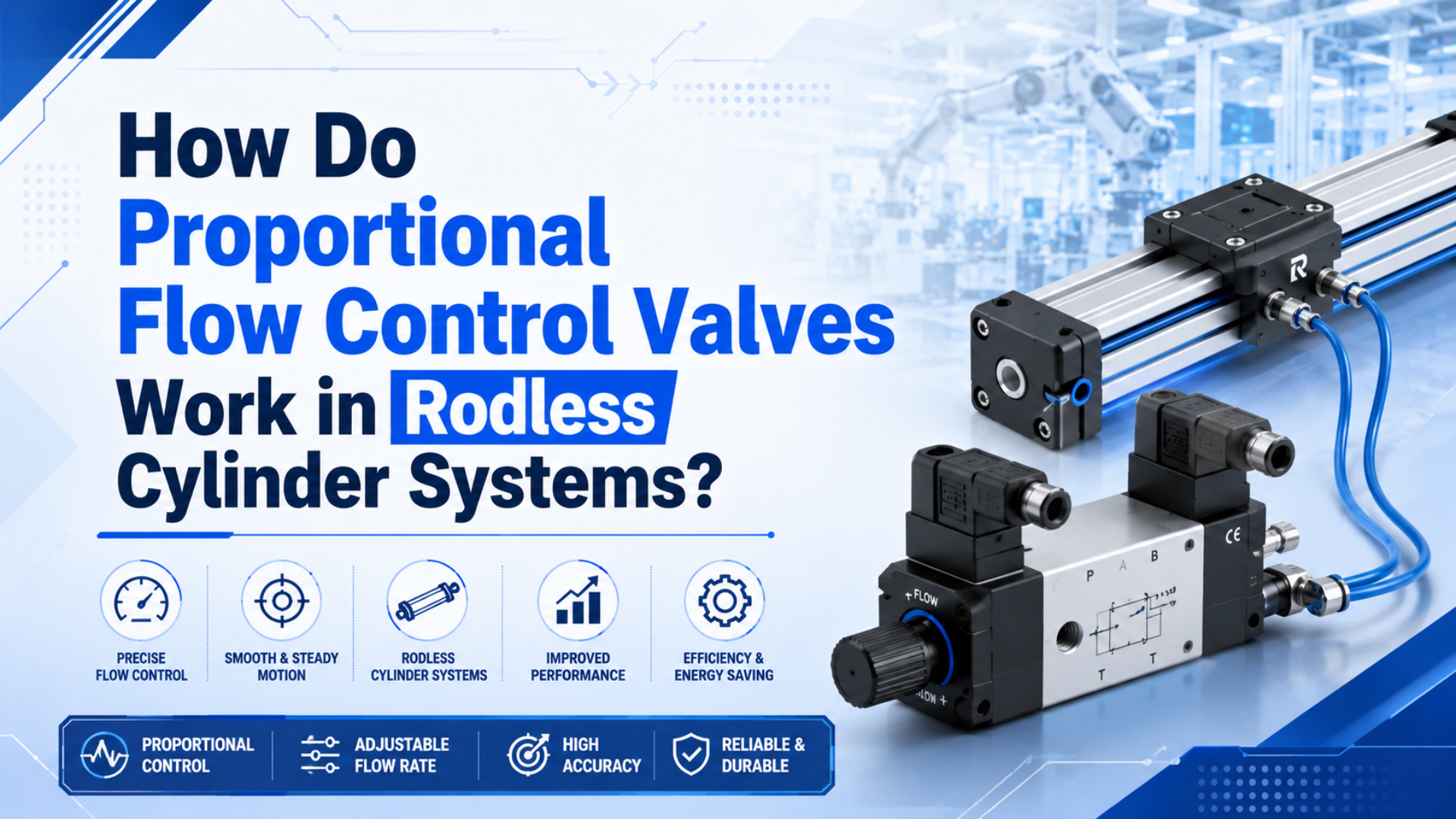
Proportional flow control valves work in rodless cylinder systems by changing the valve opening in proportion to an electrical command. Instead of snapping fully open like a standard solenoid valve, the valve meters supply or exhaust air so the carriage can accelerate, travel, and decelerate with a controlled speed profile.
That distinction matters most on long-stroke rodless axes. A basic on/off circuit can move the carriage from end to end, but it cannot shape the stroke well when load, product handling, end impact, or PLC-controlled recipe changes matter.
Key Takeaways
- Festo lists proportional-valve setpoints such as 0-10 V and 4-20 mA.
- SMC says meter-out flow control gives stable speed adjustment against load fluctuation.
- In rodless systems, valve choice must match bore, stroke, tube size, load, cushioning, and PLC timing details.
A proportional valve does not turn a pneumatic axis into a perfect servo axis by itself. It gives the controller a variable air restriction. The rodless cylinder still needs good guidance, clean air, correct exhaust capacity, and feedback where position accuracy matters.
What Are Proportional Flow Control Valves?
Proportional flow control valves are pneumatic valves that vary flow in response to an electrical command instead of switching only on or off. Festo lists proportional-valve setpoints such as 0-10 V and 4-20 mA, while Burkert Type 8605 converts external standard signals into PWM output for proportional valves (Festo, 2026; Burkert, 2026).
In a rodless cylinder system, the valve’s job is to shape how quickly air enters or leaves the cylinder chambers. The rodless carriage follows the internal piston, so sudden pressure changes can become sudden carriage motion. That can be fine for a simple transfer. It can be ugly near a fragile product, hard stop, or long guide.
A proportional flow valve normally sits in one of three control roles:
- Meter-in control, restricting air entering the active chamber.
- Meter-out control, restricting exhaust air leaving the inactive chamber.
- Bi-directional control, coordinating both directions or both chambers.
The valve does not know the load by magic. It receives an analog, PWM, or digital command. The machine controller must decide the command based on the required speed, stroke segment, product state, and sensor feedback.
How Does the Electrical Signal Become Airflow?
The electrical signal becomes airflow when electronics drive a proportional solenoid or actuator that moves a flow-control element. Burkert says Type 8605 converts external standard signals into PWM signals for infinitely adjustable valve opening, and SMC’s PVQ documentation links applied current to electromagnetic attraction force and flow rate (Burkert, 2026; SMC PVQ, 2026).
The simplified chain looks like this:
PLC command -> valve electronics -> coil current -> armature movement -> orifice area -> airflowOn a 0-10 V command, the controller may send a low voltage for creep speed, a mid voltage for normal travel, and a lower voltage again for deceleration. On a 4-20 mA loop, the current provides the setpoint. The valve electronics translate that signal into coil drive.
Open-loop proportional control sets a command and assumes the resulting speed is acceptable. Closed-loop control measures carriage position, speed, pressure, or valve position and adjusts the command. Rodless cylinder positioning becomes much more predictable when feedback is part of the design.
How Do Proportional Valves Control Rodless Cylinder Speed?
Rodless cylinder speed is controlled by managing chamber filling and chamber exhaust. SMC says meter-out control makes speed adjustment easy and gives stable speed against load fluctuations, while CAGI recommends no more than 10% pressure drop from compressor discharge to point of use (SMC FAQ, 2026; CAGI, 2026).
Meter-in control restricts supply air. It can work well when the load is stable and the rodless carriage is moving against a predictable resistance. It is simple, but it can become unstable when the load helps the motion.
Meter-out control restricts exhaust air. It often gives better control because back pressure resists runaway motion. On vertical or varying-load axes, exhaust control can prevent a carriage from lunging when the load changes direction or friction drops.
In many rodless systems, speed control has three zones:
- Start slowly so seals, guides, and load tooling do not shock.
- Travel at a higher speed through the middle of the stroke.
- Slow down before the end stop or cushion zone.
That profile is hard with a plain on/off valve. A proportional valve can receive a different command in each zone, but the cylinder still needs enough flow capacity. If tubing and mufflers are too small, the valve command will not produce the expected speed.
What Components Make the Valve Work?
The working parts are the command interface, control electronics, proportional solenoid or actuator, flow-control element, housing, and optional feedback. SMC’s PVQ material describes current changing electromagnetic attraction force and armature stroke, while TE Connectivity explains that LVDT output varies with core position (SMC PVQ, 2026; TE Connectivity, 2026).
Most proportional valves include:
- Signal conditioning for the command input.
- Coil or actuator drive electronics.
- A moving armature, spool, needle, poppet, or other flow element.
- Seals and ports sized for the air path.
- Adjustment or diagnostic features depending on the model.
Feedback can appear in two places. Some valves monitor internal valve position. Some systems monitor cylinder carriage position with an external sensor. These are not interchangeable. Valve-position feedback tells you the valve moved. Carriage feedback tells you the actuator moved.
For rodless cylinders, carriage feedback is often the more useful machine signal. It can catch load slip, guide binding, pressure starvation, and end-position errors that a valve-only signal cannot see.
Open-Loop vs Closed-Loop Control
Open-loop control sends a command without measuring the resulting carriage speed or position, while closed-loop control corrects the command using feedback. Enfield’s S2 positioning system combines proportional valve technology, sensors, and embedded control electronics, and its rodless-cylinder demo shows external feedback used for velocity and position control (Enfield Technologies, 2026; Enfield video, 2026).
Open-loop proportional control can be enough for soft start, soft stop, and approximate speed selection. It works best when:
- Load mass is consistent.
- Pressure is stable.
- Friction does not change much.
- End-position accuracy is enough.
- The machine only needs a smoother stroke, not a commanded stop anywhere.
Closed-loop control is different. The controller compares measured position or velocity against the target and adjusts the valve command. It is useful when the machine needs intermediate stops, recipe-based positions, load variation compensation, or better fault detection.
From control-panel discussions, the common misunderstanding is assuming the proportional valve alone gives positioning. It gives a variable air command. Positioning needs a target, feedback, tuning, and a cylinder installation that can respond repeatably.
How Should You Size a Proportional Valve?
Sizing starts with cylinder bore, stroke, target speed, load, tube length, port size, and allowable pressure drop. CAGI’s pressure-drop brief says pressure loss can come from pipes, fittings, filters, dryers, and point-of-use components, and recommends a 10% maximum system pressure drop (CAGI, 2026).
A proportional valve that is too small will flatten the speed curve. The PLC may command 80%, but the cylinder will still move slowly because the valve, fitting, or muffler cannot pass enough air.
A valve that is too large can be difficult to tune. Small command changes may create large flow changes. The carriage may creep, jump, or become sensitive to pressure and friction changes. Bigger is not automatically better.
Use this RFQ sequence:
| Sizing input | Why it matters | What to send |
|---|---|---|
| Bore and stroke | Sets chamber volume and flow demand | Cylinder model or bore/stroke |
| Moving mass | Sets acceleration and stop energy | Carriage load and tooling weight |
| Stroke time | Defines required average speed | Target extend and retract time |
| Tube and port size | Can restrict flow | Valve port, tube OD, fitting route |
| Control signal | Matches PLC hardware | 0-10 V, 4-20 mA, PWM, fieldbus |
| Feedback | Decides open or closed loop | End switches, encoder, LVDT, sensor |
PLC Signals and Recipe Control
PLC integration depends on matching the valve command interface to the controller output. Festo lists proportional-valve setpoint options such as analog voltage and current, including 0-10 V and 4-20 mA, while Burkert describes external standard signals driving proportional valve electronics (Festo, 2026; Burkert, 2026).
A simple recipe might use three command values:
Start zone: 20%
Travel zone: 65%
Deceleration zone: 25%
Those numbers are not universal. They are commissioning values. The right commands depend on cylinder volume, supply pressure, valve size, tubing, mufflers, load, guide friction, and whether the circuit is meter-in or meter-out.
For PLC programming, treat proportional flow as an analog output with machine-state rules. The PLC should know when the carriage is at home, when it enters a slow zone, when it reaches the end sensor, and when a timeout should fault the cycle.
Useful interlocks include:
- Air pressure available.
- Cylinder home confirmed.
- Guard or product clear.
- Analog output within allowed range.
- End sensor reached within timeout.
- Position or speed feedback plausible.
If the machine has multiple product sizes, proportional control can store different speed profiles by recipe. Keep the recipe names tied to the actual load and product state, not just “fast” and “slow.” Future technicians will thank you.
Where Do Rodless Cylinders Need Extra Care?
Rodless cylinders need extra care because the moving carriage can carry moment loads that a plain valve cannot fix. The companion rodless air slide draft cites SMC MY1B operating pressure of 0.1-0.8 MPa and 100-1000 mm/s piston speed for one guided specification, so speed must be checked with guide load, not alone (SMC MY1B catalog, 2025).
Proportional flow can make motion smoother, but it cannot remove mechanical overload. If the tooling hangs far from the carriage, the guide sees pitch, yaw, or roll moment. If the stroke ends against a hard stop, the guide and coupling see impact energy.
Check these rodless-axis details before blaming the valve:
- Moving mass and offset from the carriage centerline.
- Horizontal or vertical mounting orientation.
- Guide moment rating and safety margin.
- Cushion or shock absorber method.
- Coupling type and jam behavior.
- Tube route and moving cable clearance.
- Sensor location and repeatability requirement.
If the axis needs many intermediate stops, a proportional flow valve may still be only part of the answer. The system may need position feedback, a pneumatic positioning controller, external stops, brakes, or an electric actuator. The honest requirement comes first.
For the base actuator concept, use the related article on how a rodless air slide works. This page stays focused on proportional valve control, PLC signals, and speed tuning so the two articles do not compete for the same search intent.
What Problems Do Proportional Valves Solve?
Proportional valves mainly solve abrupt starts, harsh stops, fixed-speed limitations, and recipe-dependent speed changes. SMC’s meter-out guidance supports stable speed adjustment under load fluctuation, and Enfield’s S2 system shows proportional valve control combined with sensors and embedded electronics for pneumatic positioning (SMC FAQ, 2026; Enfield Technologies, 2026).
Good use cases include:
- Packaging transfers that need gentle product pickup.
- Long rodless strokes that hit end cushions too hard.
- Load changes between product recipes.
- Slow approach into a fixture.
- Two-speed or three-speed transfer motion.
- PLC-supervised speed changes without manual flow-control adjustment.
Bad use cases also exist. A proportional valve is not the first fix for dirty air, wrong bore size, loose guide hardware, worn seals, blocked mufflers, or bad load alignment. It can hide some symptoms during commissioning, but the root problem will return.
The best proportional-valve projects begin with a boring checklist. Is the cylinder correctly sized? Is pressure stable during motion? Are guides carrying the moment? Is exhaust free enough? If not, the control loop is being asked to repair mechanics.
How Should You Commission the System?
Commissioning should start at low speed and real load, then build the profile in steps. DOE says compressed-air leaks can waste 20-30% of compressor output in poorly maintained systems, so leak and pressure checks belong before tuning any proportional pneumatic axis (DOE Sourcebook, 2016).
Use this practical sequence:
- Confirm air preparation and working pressure.
- Check the cylinder and rodless guide without production load if safe.
- Verify valve wiring, command type, and fail state.
- Start with a low command and short jog.
- Tune meter-out behavior before increasing travel speed.
- Add deceleration before end cushions or stops.
- Record final command values by recipe.
- Lock unsafe values out of the HMI.
Measure during motion. Static pressure, idle current, and unloaded motion can all look clean while the loaded axis is unstable. Trend carriage time, end-sensor timing, pressure drop, and fault count after the first production shift.
For RFQs, send the valve signal type, cylinder bore and stroke, moving mass, target stroke time, mounting orientation, tube length, port size, feedback type, and the current problem. “Jerky motion” is a symptom. The details tell the engineer where to look.
Conclusion
Proportional flow control valves work in rodless cylinder systems by turning a 0-10 V, 4-20 mA, PWM, or digital command into a controlled air restriction. Festo and Burkert document standard signal interfaces, SMC supports meter-out speed stability, and CAGI’s 10% pressure-drop target explains why the surrounding air path still matters (Festo, 2026; SMC FAQ, 2026; CAGI, 2026).
Use proportional valves when the rodless axis needs smoother motion, recipe-based speed, soft approach, or PLC-tuned stroke profiles. Do not use them as a cover for undersized valves, dirty air, bad exhaust, guide overload, or missing feedback. Good pneumatic control still starts with good mechanics.
FAQs About Proportional Flow Control Valves
FAQ answers should keep the signal, valve, controller, feedback, and rodless cylinder separate. Festo lists 0-10 V and 4-20 mA setpoint examples, SMC supports meter-out stability against load fluctuation, and Enfield shows proportional control plus sensors for pneumatic positioning (Festo, 2026; SMC FAQ, 2026; Enfield Technologies, 2026).
How do proportional flow control valves work?
They convert an electrical command into a variable valve opening. The command can come from a PLC analog output, PWM controller, or fieldbus device. The valve electronics drive a solenoid or actuator, which changes the orifice area and meters air to or from the cylinder.
Are proportional valves the same as servo valves?
No. A proportional valve varies flow or pressure according to a command, but a servo system usually implies tighter feedback and dynamic control. Some pneumatic positioning systems combine proportional valves with sensors and embedded controllers, but the valve alone does not guarantee servo-level positioning.
Should I use meter-in or meter-out control?
Meter-out control is often preferred for pneumatic cylinder speed because controlling exhaust can stabilize motion under changing load. Meter-in can work for steady loads and simple circuits. The final choice depends on mounting orientation, load direction, safety state, and whether the carriage can overrun.
Can a proportional valve stop a rodless cylinder mid-stroke?
It can help, but mid-stroke stopping usually needs feedback, control logic, and sometimes external holding or braking. Pneumatic air compressibility and changing friction make open-loop mid-stroke stopping uncertain. For repeatable intermediate positions, specify the full positioning system, not only the valve.
What information should I send for a proportional valve RFQ?
Send cylinder bore, stroke, moving mass, mounting orientation, target speed profile, current valve size, tube length, port size, pressure during motion, PLC output type, feedback devices, expected stop accuracy, environment, and photos. Include whether the issue is jerk, impact, speed variation, or positioning.
Why does the cylinder still jerk after adding a proportional valve?
Common causes include undersized exhaust, high static friction, guide overload, poor cushioning, command steps that change too sharply, dirty air, or missing feedback. Tune the profile at real load and check pressure at the cylinder ports during motion before increasing the command.
Sources
- Festo: Proportional valves, proportional valve category and setpoint examples including 0-10 V and 4-20 mA. Retrieved 2026-06-03.
- Burkert: Type 8605 PWM control electronics for proportional valves, external standard signal conversion into PWM output for proportional valve opening. Retrieved 2026-06-03.
- SMC: Flow Control Equipment FAQ, meter-out control and speed stability against load fluctuation. Retrieved 2026-06-03.
- SMC: Compact Proportional Solenoid Valve PVQ Series, applied current, electromagnetic attraction force, armature stroke, and flow-rate relationship. Retrieved 2026-06-03.
- TE Connectivity: LVDT basics, position feedback principle for linear variable differential transformers. Retrieved 2026-06-03.
- Enfield Technologies: S2 Low-Flow Cylinder Positioning System, proportional valve, sensors, and embedded electronics for pneumatic positioning. Retrieved 2026-06-03.
- Enfield Technologies video: S2 Positioning - Better Rodless Cylinder Positioning, rodless cylinder positioning demonstration with external feedback. Retrieved 2026-06-03.
- CAGI: Technical Brief on Pressure Drop, 10% pressure-drop target and compressed-air restriction guidance. Retrieved 2026-06-03.
- DOE: Improving Compressed Air System Performance, Third Edition, compressed-air leak loss ranges and system troubleshooting context. Retrieved 2026-06-03.