

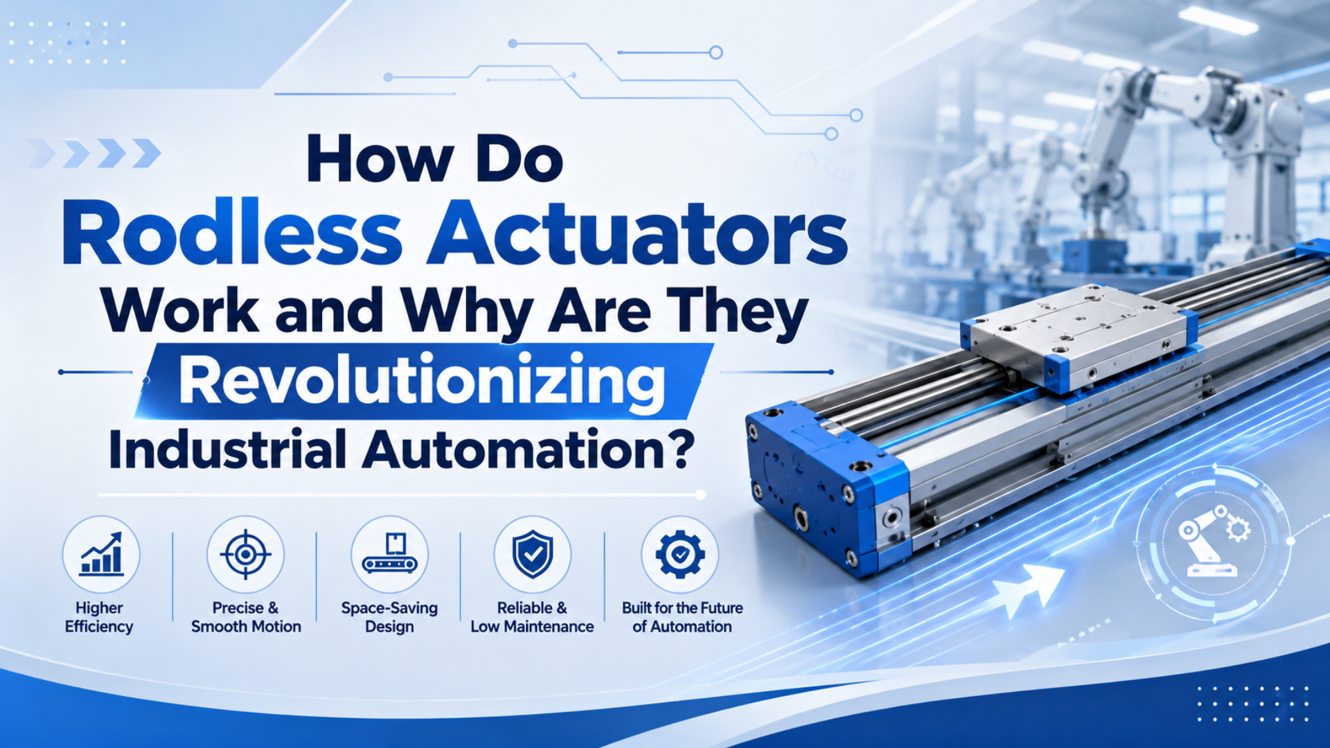
Rodless actuators work by moving a carriage, slide, or tooling plate along a linear path without sending a piston rod outside the actuator body. Pneumatic rodless cylinders do this with an internal piston and an external carriage. Electric rodless actuators do it with a belt, screw, or motor-driven carriage.
The useful idea is compact linear motion. The risky part is oversimplifying it.
In automation projects, a rodless actuator is not just a shorter cylinder. It is a linear axis with thrust, guidance, controls, energy supply, mounting, and maintenance requirements. Parker publishes OSP-P rodless pneumatic cylinders with standard strokes up to 6000 mm and long-stroke versions up to 41 m (Parker OSP-P catalog, 2025). That kind of range changes machine layout, but it does not remove the need for load and control checks.
Key Takeaways
- Rodless actuators reduce rod-extension space, but the guide and coupling decide whether the axis survives.
- Parker lists OSP-P 10-80 mm bores, 8 bar maximum pressure, and standard strokes up to 6000 mm.
- DOE puts compressed-air wire-to-work efficiency around 10%, so pneumatic and electric actuator choices should include utilities and control needs.
What Is a Rodless Actuator?
Rodless actuator is the broad name for a linear actuator that moves a carriage without an exposed piston rod. AutomationDirect describes rodless cylinders as using an internal piston connected to an external carriage that moves along the cylinder body, reducing the extra rod-extension space required by a rodded cylinder (AutomationDirect, 2020).
That definition includes several families. Pneumatic rodless cylinders use compressed air and a piston. Magnetic rodless cylinders transfer force through a closed tube using magnets. Mechanically coupled or band-style cylinders use a sealed slot and carriage connection. Electric rodless actuators use a motor-driven belt, screw, or linear stage.
This article treats them as a selection family, not as one interchangeable part. If you only need a simple long-stroke pneumatic transfer, start with a rodless cylinder category. If you need programmable positions, compare the complete control package before assuming air or electric wins.
For narrower mechanical detail, use the companion pages on rodless air slide operation and magnetic rodless cylinder operation. This page stays one level higher: which rodless actuator type fits the automation job?
How Do Rodless Pneumatic Actuators Transfer Motion?
Rodless pneumatic actuators transfer motion by moving an internal piston and carrying that motion to an external carriage. Parker’s OSP-P data lists 10-80 mm bores, 8 bar maximum operating pressure, and standard strokes up to 6000 mm (Parker OSPP Series, 2026). The mechanism is compact, but the load path still matters.
The basic air-powered sequence is:
- A solenoid valve sends compressed air to one cylinder chamber.
- Pressure acts on the piston area and creates thrust.
- The opposite chamber exhausts through the valve and muffler.
- A magnetic, band, cable, or mechanical joint transfers motion to the carriage.
- The guide system carries side load, overhung load, and stopping impact.
Use the simple force relation as a first pass:
Force = pressure x effective piston areaThat line is only the start. It does not include seal drag, guide friction, pressure drop, acceleration force, coupling margin, vertical load, or cushioning. In our experience, most wrong rodless selections fail in one of those details, not in the basic pressure-area math.
The clean way to think about a pneumatic rodless actuator is three systems in one body: air creates force, the coupling transfers force, and the guide protects the load path. If the quote only lists bore and stroke, it is missing two-thirds of the real decision.
Rodless Actuator Technology Comparison
The main rodless technologies are pneumatic rodless cylinders, magnetically coupled cylinders, mechanically jointed or band-style cylinders, and electric rodless axes. SMC’s MY1B catalog lists 0.1-0.8 MPa operating pressure and 100-1000 mm/s piston speed for one mechanically jointed rodless specification (SMC MY1B catalog, 2025).
Magnetic rodless designs are useful when a closed pressure tube and clean outside geometry matter. There is no slot along the cylinder barrel. That can help with cleanliness, but the magnetic coupling force becomes a hard limit. Heat, air gap, impact, and ferrous debris reduce margin.
Mechanically coupled and band-style designs are usually better when positive force transfer matters more than a closed tube. They can carry higher thrust in many catalog families, but the seal band, cover strip, guide, and carriage alignment become inspection items.
Electric rodless actuators are different. They usually win when the machine needs programmable intermediate positions, speed profiles, recipe changes, or repeatable acceleration control. They also need a motor, drive, controller, cables, and commissioning work. Do not compare only actuator body prices.
| Type | Strong fit | Weak fit | Buying question |
|---|---|---|---|
| Pneumatic rodless cylinder | Fast two-position transfer, long stroke, simple automation | Many programmable stops | Is the air path sized for moving pressure? |
| Magnetic rodless cylinder | Clean moderate-load motion | High shock, metal chips, vertical safety loads | Is coupling force higher than worst-case load? |
| Mechanically jointed or band type | Higher thrust and guided carriage packages | Dirty seal bands or poor alignment | Are moment, cushioning, and seal access checked? |
| Electric rodless actuator | Position profiles and recipe-driven motion | Very simple low-cost two-position tasks | Does the TCO justify motor and drive hardware? |
Why Do Rodless Actuators Change Machine Layouts?
Rodless actuators change machine layouts because useful travel happens along the actuator body instead of beyond an extending rod. Parker publishes OSP-P standard stroke choice up to 6000 mm and long-stroke versions up to 41 m (Parker OSP-P catalog, 2025). That lets long transfer axes fit inside shorter frames.
A rodded cylinder needs room for the barrel and the extended rod. If a machine needs a long horizontal push, that extra rod clearance can invade guarding, conveyors, operator space, or neighboring stations. A rodless actuator keeps the moving load beside the actuator.
Still, “shorter” is not automatically “easier.” You still need clearance for the carriage, sensors, tubing, valve access, cable chains, stops, shock absorbers, and service space. A compact CAD model can become difficult to maintain if the fittings face a wall.
In replacement RFQs, the best layout sketches show the stroke, carriage overhang, tube direction, sensor side, and guard clearance. Photos help, but a simple hand sketch with dimensions often prevents a wrong quote faster than a perfect part number.
For product-level matching, compare OSP-P modular rodless cylinders, DGC rodless cylinders, and MY1H precision rodless cylinders against the actual load path.
When Is Pneumatic Rodless Better Than Electric?
Pneumatic rodless actuators are often better when the machine needs fast, simple, mostly two-position motion and already has clean compressed air. DOE puts compressed-air systems at about 10% wire-to-work efficiency, so the choice should still include energy and air-system health (DOE Sourcebook, 2016).
Use pneumatic rodless motion when the work is a transfer, push, shuttle, eject, gate, or stop with a small number of positions. The circuit can be straightforward: a directional valve, flow controls, cylinder sensors, cushioning, and an FRL unit.
The strongest pneumatic case appears when the factory already maintains compressed air well. Short tubing, correct valve flow, dry air, clean filters, and measured point-of-use pressure can make the axis simple and durable.
The weak pneumatic case appears when the process needs many intermediate positions, frequent recipe changes, high precision, or detailed acceleration profiles. You can add proportional valves and feedback, but at some point the pneumatic axis stops being simple.
When Is Electric Rodless Better Than Pneumatic?
Electric rodless actuators are often better when the motion needs programmable position, speed, acceleration, or force control. Tolomatic defines total cost of ownership as initial purchase cost plus years of service multiplied by yearly operating cost, including replacement, maintenance, utilities, scrap, and lost production (Tolomatic, 2017).
That TCO framing matters because electric actuators usually cost more upfront. If the machine needs adjustable stops, recipe changes, lower air use, or better position feedback, the extra hardware may pay for itself. If the job is a simple end-to-end transfer, it may not.
Electric rodless axes also simplify some control architecture. A motor drive can command position directly. The PLC can store recipes. The same axis can run different strokes during changeover. Pneumatics can do this too, but only with additional feedback and control hardware.
The weak electric case appears in wet, dirty, low-cost, or very simple two-position work where a pneumatic cylinder and valve are easier to maintain. Look at the whole environment. Motor, drive, cable, connector, cabinet, and service skill all count.
How Should You Size a Rodless Actuator?
Size a rodless actuator from thrust, moving mass, speed, guide moment, environment, and control requirement. SMC rodless selection data uses load-factor checks for static load and dynamic moment, and warns designers to change speed, bore, or guide arrangement when the total load factor exceeds 1 (SMC selection PDF, 2024).
Start with load and orientation. Record the moving mass, tooling weight, product weight, mounting direction, and any vertical load. Then mark the offset from the carriage centerline. A light tool mounted far away can overload the guide faster than a heavier load mounted close.
Next, check speed and stops. Stroke time creates acceleration force and end impact. A high-speed shuttle may need larger cushioning, shock absorbers, or a slower motion profile. Turning up pressure is not the universal cure.
Then check the air or electrical supply. For pneumatic axes, CAGI says a well-designed compressed-air system should have no more than 10% pressure drop from compressor discharge to point of use (CAGI, 2026). For electric axes, check drive sizing, motor torque, duty cycle, and thermal limits.
A useful RFQ line looks like this: “Stroke 1800 mm, horizontal transfer, 18 kg moving mass, 110 mm carriage offset, extend in 1.5 s, two end sensors, 0.6 MPa measured pressure during motion, no washdown.” That gives engineering something real to size.
What Installation Checks Prevent Early Failure?
Installation checks should focus on alignment, support, air quality, cable or tube routing, sensor position, and stop impact. ISO 8573-1 classifies compressed-air purity by particles, water, and oil, which is why pneumatic rodless axes need specified air quality instead of guessed filtration (ISO 8573-1, 2010).
Mount the actuator on a rigid surface. Long extrusions can twist if the base is uneven. Use intermediate supports when the catalog requires them, especially on long strokes or horizontal spans.
Keep the guide and load aligned. A rodless actuator is not a structural beam for random side load. If the carriage carries a tall bracket, check pitch, roll, and yaw moment before commissioning.
Route tubing and cables so they do not pull on the carriage. Push-in fittings, polyurethane tubing, sensor cables, and cable chains should move without dragging the load or blocking maintenance access.
Commission slowly. Run low speed first, verify sensors, check end cushioning, measure pressure during motion, and look for binding. The best time to find a wrong guide load is before the machine starts production.
Troubleshooting Rodless Actuator Problems
Troubleshooting should separate air supply, force transfer, guide load, controls, and environment first. DOE gives a point-of-use filter example with a 20 psi pressure drop, showing why local pressure during motion can differ sharply from header pressure (DOE Sourcebook, 2022).
If the axis is weak, measure pressure at the actuator while it moves. Do not trust only the regulator gauge. A small valve, clogged filter, long tube, or blocked muffler can make a good cylinder act weak.
If the carriage slips or loses position, check the coupling or drive mechanism. Magnetic units can decouple when load, acceleration, impact, heat, air gap, or contamination reduces the margin. Band units can bind when the seal strip, carriage, or guide is misaligned.
If positioning is inconsistent, separate the mechanical problem from the control problem. Verify sensors, homing routine, PLC timing, valve response, and physical stops. With electric axes, also check drive alarms, encoder feedback, and motor current.
If wear is early, inspect the environment. Dust, water, oil mist, metal chips, heat, and washdown can change the correct actuator family. A clean-room magnetic unit and a band-style actuator for dirty packaging work are not the same purchase.
FAQs About Rodless Actuators
These answers keep the broad rodless actuator topic separate from more specific rodless cylinder pages. Parker lists OSP-P 10-80 mm bores and 8 bar maximum operating pressure, while SMC lists 0.1-0.8 MPa for one MY1B guided rodless specification (Parker, 2026; SMC, 2025).
How do rodless actuators work?
Rodless actuators move a carriage without an exposed piston rod. Pneumatic versions move an internal piston and transfer force to the carriage by magnetic coupling, band, cable, or mechanical joint. Electric versions move the carriage with a motor-driven belt, screw, or linear stage.
Are rodless actuators the same as rodless cylinders?
No. A rodless cylinder is usually a pneumatic rodless actuator. Rodless actuator is the broader term, because it can include pneumatic cylinders, magnetically coupled cylinders, mechanically jointed cylinders, belt-driven electric axes, screw-driven stages, and other linear motion packages without an exposed piston rod.
Why use a rodless actuator instead of a standard cylinder?
Use a rodless actuator when stroke length or rod-extension space makes a standard cylinder awkward. A standard rod cylinder needs clearance for the extending rod. A rodless design keeps the carriage moving along the body, which can simplify long transfer axes and guarded machine frames.
When should I choose pneumatic rodless instead of electric?
Choose pneumatic rodless when the task is fast, mostly two-position, and the plant already has clean compressed air. Choose electric when the job needs many programmable positions, controlled acceleration, recipe changes, or detailed feedback. Compare total installed cost, not only actuator price.
What information should I send for a rodless actuator quote?
Send stroke, moving mass, load offset, mounting orientation, speed target, number of positions, available pressure or power, sensor needs, environment, stop method, cycle rate, photos, and a sketch. For pneumatic axes, include measured pressure during motion and the valve or tubing details if known.
Sources
These sources were selected to support the family-selection angle without repeating narrower rodless air slide or magnetic rodless cylinder pages. The highest-use data points are Parker’s 6000 mm OSP-P standard stroke, SMC’s 0.1-0.8 MPa MY1B range, DOE’s 10% compressed-air efficiency context, and CAGI’s 10% pressure-drop guidance.
-
AutomationDirect: Rodless Cylinders Provide a Compact Pneumatic Linear Motion Option, internal piston and external carriage explanation. Retrieved 2026-06-03.
-
Parker: OSPP Series, bore sizes, 6000 mm maximum standard stroke, 8 bar maximum pressure, and long-stroke availability. Retrieved 2026-06-03.
-
Parker: OSP-P Pneumatic Rodless Cylinders and Linear Guides catalog, 10-80 mm bores, 8 bar operating pressure, 6000 mm standard strokes, and long-stroke versions up to 41 m. Retrieved 2026-06-03.
-
SMC: MY1B Mechanically Jointed Rodless Cylinder catalog, 0.1-0.8 MPa operating pressure and 100-1000 mm/s piston speed. Retrieved 2026-06-03.
-
SMC: MY1B-Z mechanically jointed rodless cylinder selection data, guide-load and dynamic-moment selection logic. Retrieved 2026-06-03.
-
U.S. Department of Energy: Improving Compressed Air System Performance, Third Edition, compressed-air efficiency and point-of-use pressure-drop examples. Retrieved 2026-06-03.
-
CAGI: Working With Compressed Air, pressure-drop guidance from compressor discharge to point of use. Retrieved 2026-06-03.
-
ISO 8573-1:2010, compressed-air purity classes for particles, water, and oil. Retrieved 2026-06-03.
-
Tolomatic: Total Cost of Ownership, Pneumatic vs Electric Linear Actuators, total-cost framing for pneumatic and electric linear actuator comparisons. Retrieved 2026-06-03.
-
Enfield Technologies video: S2 Positioning - Better Rodless Cylinder Positioning, rodless cylinder positioning demonstration used for the embedded video. Retrieved 2026-06-03.