

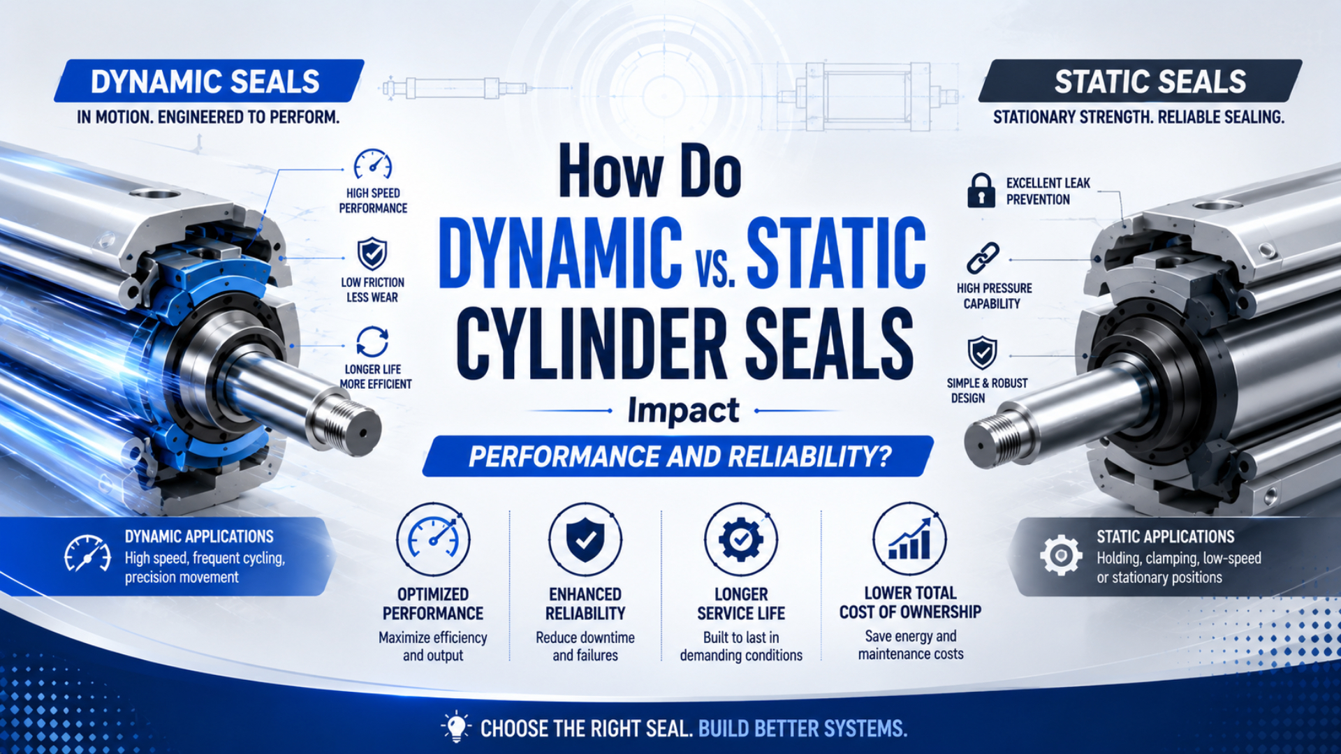
A dynamic cylinder seal is a seal that works against a moving rod, piston, carriage, or rotating surface, so its design must balance leakage control with friction, lubrication, heat, and wear. A static cylinder seal is a seal that closes a joint whose mating surfaces don’t move during normal operation. That interface distinction, not color or generic shape, determines the engineering problem.
An O-ring proves the point. It is common in static joints, yet Parker publishes separate guidance for pneumatic reciprocating O-ring seals. A seal profile isn’t automatically static or dynamic. Its groove, squeeze, mating surface, pressure direction, speed, material, and lubrication must suit the actual motion.
TL;DR: Parker’s pneumatic guidance allows only 1% to 3% circumferential compression for an O-ring used as a rod seal. That narrow, product-specific range shows why dynamic and static grooves aren’t interchangeable. Classify the interface first, then check leakage path, friction, surface condition, guidance, material, and test evidence.
Where Are Dynamic and Static Seals Located Inside a Cylinder?
Trelleborg separates pneumatic sealing hardware into 6 functional groups: rod seals, piston seals, rod-seal/scraper combinations, static seals, scrapers, and wear or cushioning elements. The practical answer is location-based: moving rod and piston interfaces are dynamic, while end-cap, port, and tube joints are normally static (Trelleborg Pneumatic Seals, accessed 2026).
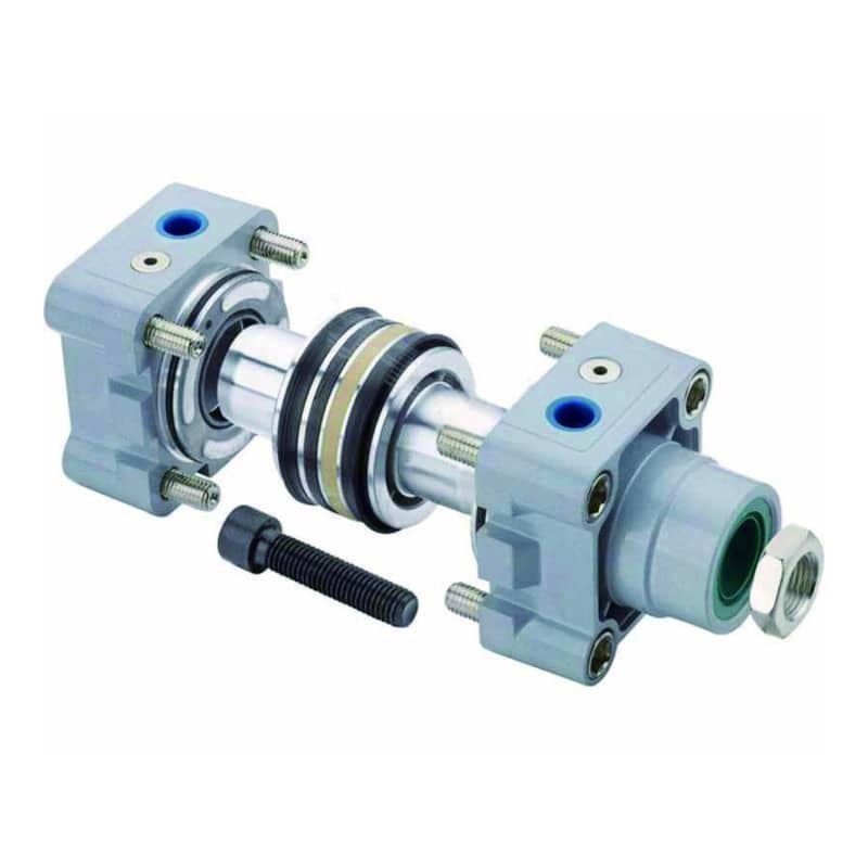
Four interface zones cover most rod-style pneumatic cylinders:
| Interface zone | Relative motion in normal operation | Main component | Leakage or damage to watch for |
|---|---|---|---|
| Tube to end cap, port, cushion screw | None | Static O-ring or gasket | External leakage at a fixed joint |
| Piston to cylinder bore | Reciprocating | Dynamic piston seal | Chamber-to-chamber bypass, weak thrust, drift |
| Rod to head or gland | Reciprocating | Dynamic rod pressure seal | Air leakage to atmosphere at the rod end |
| Rod entry and piston guidance | Reciprocating contact, but different jobs | Wiper and wear ring | Contamination entry, one-sided wear, scoring |
A wiper and a wear ring need separate labels. The wiper excludes dirt, moisture, chips, or washdown residue before they reach the rod seal. The wear ring guides the moving assembly and carries permitted transverse reaction. Neither should be assumed to be the primary pressure seal.
Why does this matter during repair? Air heard at the rod end points toward a different interface than internal bypass between chambers. Replacing every black polymer ring as one undifferentiated “seal kit” can hide the original failure path.
For a broader catalog of profiles and applications, use the industrial cylinder seal types guide. This article stays with the motion interface and the evidence needed to diagnose it.
The most useful first question is not “Which rubber do I need?” It is “Which two surfaces move relative to each other when the cylinder cycles?” That question separates fixed-joint leakage, piston bypass, rod-end leakage, and guide damage before material selection begins.
Can the Same O-Ring Work as Both a Static and Dynamic Seal?
Yes, but the installation rules change. Parker’s pneumatic O-ring handbook permits 1% to 3% circumferential compression for rod-seal use and up to 6% inner-diameter stretch for piston use. Those are design-specific values, not permission to move a static-joint O-ring into any dynamic gland (Parker O-Ring Handbook, accessed 2026).
In a static joint, controlled squeeze creates contact stress against surfaces that remain fixed. Long-term relaxation, compression set, thermal cycling, chemical swelling, groove fill, and assembly damage dominate the review. Since there is no continuous sliding, breakaway and running friction aren’t normal operating losses.
In a dynamic gland, that same basic ring may slide, roll, twist, or briefly lose its lubricant film. The design now has to control friction and wear while retaining enough contact stress to seal. Parker’s handbook treats speed, pressure direction, squeeze, groove shape, temperature, stroke length, surface finish, lubrication, and backup support as linked variables.
So, can a maintenance technician use an O-ring temporarily in a rod gland? Only when the cylinder manufacturer or a qualified seal supplier confirms the exact profile, compound, dimensions, groove, surface, pressure, temperature, speed, and lubricant. A visual match doesn’t establish dynamic suitability.
| Question | Static interface | Dynamic interface |
|---|---|---|
| What creates the seal? | Controlled compression at a fixed joint | Contact stress maintained while surfaces move |
| What usually limits reliability? | Set, aging, swelling, groove fill, installation nicks | Friction, wear, stick-slip, heat, contamination, extrusion, twist |
| Which surface matters most? | Groove and fixed mating faces | Moving rod or bore plus groove and lead-in edge |
| What must test evidence include? | Pressure, medium, temperature, duration | Static conditions plus speed, stroke, cycle profile, lubrication, reversals |
Trelleborg calls the O-ring the most common static seal, but its definition is still based on no movement between sealing surfaces. “Most common” isn’t “static only” (Trelleborg Static Seals, accessed 2026).
How Does Motion Change Friction, Leakage, Wear, and Reliability?
Parker divides dynamic seal friction into 2 states, break-out friction and running friction. A cylinder can therefore seal at rest yet hesitate when motion begins, or move acceptably after breakaway while wearing rapidly. Dynamic reliability is the balance among contact stress, lubricant film, surface texture, pressure, alignment, and contamination (Parker O-Ring Handbook, accessed 2026).
More interference isn’t automatically safer. Extra squeeze may improve static contact at first, yet it can raise starting force, heat, wear, and the risk of twisting in a reciprocating groove. Too little contact can leak, especially at low pressure or after the elastomer relaxes. The usable window comes from the selected seal manufacturer’s design data.
Surface finish is equally important. A rough rod can abrade the lip. A damaged bore can cut the piston seal. A surface that can’t retain the intended lubricant film may increase stick-slip, while scratches aligned with the leakage path can defeat contact. Don’t specify a universal roughness value without the exact profile and material data.
What if the new seal wears on only one side? That pattern should move alignment, rod condition, bushing clearance, piston guidance, and side load above material hardness on the fault tree. A piston seal isn’t a bearing. The rod bearing and rod seal failure guide explains that load path in detail.
In our experience, the fastest inspection preserves direction. Photograph the seal before cleaning, mark the cylinder’s installed clock position, and compare lip wear with rod scratches, bushing polishing, load direction, and the stroke position where binding occurs. Washing the parts first can erase that evidence.
Dry or contaminated air also changes the result. If lubricant has been added upstream, changing its type or removing it can alter seal behavior. Use the air lubrication and seal material guide before changing the plant’s lubrication policy, and check the self-lubricating seal limitations when a catalog uses that term.
Which Failure Pattern Points to a Dynamic or Static Seal Problem?
ISO 19973-3 reports pneumatic cylinder reliability in 2 lifetime measures, cycles or kilometres, and evaluates first failure under declared test conditions. It doesn’t supply a universal replacement count. In the field, classify the leak path and physical evidence first, then compare the exact cylinder and seal kit with manufacturer limits (ISO 19973-3, confirmed 2021).
| Evidence | First interface to inspect | Don’t conclude yet |
|---|---|---|
| Bubbles or sound at an end cap, fitting, or cushion screw | Static joint, groove, seal cross-section, fastener condition | That every cylinder seal is worn |
| Air escaping at the rod end during a controlled test | Rod pressure seal, rod surface, gland, wiper | That the visible wiper is the pressure seal |
| Weak force, drift, or air passing between chambers | Piston seal, bore, piston guide, connected valve path | That external leakage must be present |
| Seal lip and bushing polished on the same side | Guidance, mounting, rod condition, side load | That harder material will correct alignment |
| Twisted or spiraled O-ring | Dynamic groove, squeeze, lubrication, stroke and pressure direction | That the compound alone caused the failure |
| Flattened, hardened, swollen, cracked, or nicked static seal | Temperature, medium, age, groove fill, assembly edge | That a universal calendar interval applies |
Troubleshooting must follow the machine’s energy-control procedure. Isolate all energy sources, secure suspended loads, release trapped pressure, and verify the safe state before disconnecting a port or opening a cylinder. Observation during a controlled cycle is different from hands-on disassembly.
If the leakage route remains uncertain, the internal cylinder leakage diagnostic provides a more detailed isolation sequence. Severe rod, bore, head, or guide damage may also shift the decision from a service kit to the repair-versus-replace framework.
What Specifications Control Dynamic and Static Seal Selection?
Trelleborg’s current pneumatic overview lists 6 functional groups, including rod seals, piston seals, combinations, static seals, scrapers, and wear or cushioning elements. That range shows why material is only one input. A useful specification identifies position, motion, pressure, speed, temperature, medium, surface, guidance, and installation constraints (Trelleborg Pneumatic Seals, accessed 2026).
Use the following sequence:
- Identify the interface and leakage direction. State whether the seal closes an end cap, separates piston chambers, retains pressure at the rod, excludes contamination, or supports guidance.
- Describe the motion. Include reciprocating or rotary motion, stroke, speed range, cycle profile, reversals, dwell time, and any vibration. “Dynamic” alone isn’t enough.
- Provide pressure conditions. Give normal regulated pressure, minimum pressure where sealing matters, transients, pressure direction, exhaust back pressure, and vacuum conditions if applicable.
- Define the environment. Record minimum and maximum temperature, compressed-air quality, added lubricant, cleaning chemicals, washdown, particles, moisture, and outdoor exposure.
- Inspect the mating hardware. Provide groove dimensions, rod or bore diameter, lead-in geometry, surface condition, damage, material, coating, alignment, and guide clearance.
- Confirm regulatory status by compound. Food-contact suitability is tied to the exact substance, manufacturer, intended use, and conditions, not a generic claim that every EPDM or silicone seal is “FDA approved” (FDA Food Contact Status, updated 2024).
- Request product-specific evidence. Ask for the drawing revision, compound designation, operating limits, installation instructions, compatibility basis, traceability, and test conditions behind any service-life claim.
Which input is easiest to miss? Minimum pressure. A pressure-energized lip or floating piston arrangement may behave differently during start-up, exhaust, low-pressure motion, or long dwell than it does at normal supply pressure. Specify the whole duty profile, not just the regulator’s maximum setting.
Static and dynamic selection should share one document but use different acceptance evidence. A static joint review emphasizes retained contact after temperature and aging. A dynamic review adds breakaway force, running friction, leakage across the travel, wear pattern, lubricant condition, and performance after reversals.
How Should Seal Life and Reliability Claims Be Validated?
ISO 19973-1 requires reliability test data to be tied to stated test conditions and statistical procedures, while Part 3 applies the method to rod cylinders. Therefore, “5 million cycles” is incomplete unless the cylinder, seal material, pressure, stroke, speed, environment, lubrication, sample count, failure threshold, and permitted maintenance are disclosed (ISO 19973-1, 2015).
Use cycle life as a conditional test result, not as a universal replacement interval. Two cylinders can record the same number of cycles while accumulating very different sliding distance, reversals, dwell time, temperature exposure, contamination, and side load. ISO 19973-3 even permits life to be reported in cycles or kilometres, reinforcing that duty description matters.
A defensible comparison should state:
- exact cylinder series, bore, stroke, rod, seal profile, and compound;
- normal and transient pressure, speed, cycle timing, load, and cushioning;
- compressed-air quality, lubricant policy, temperature, and contamination;
- sample quantity, preconditioning, inspection points, and allowed adjustment;
- leakage, friction, motion, wear, or damage threshold that defines first failure;
- whether the result is laboratory qualification, supplier validation, or field history.
Can one supplier’s test be used to rank every aftermarket kit? No. It supports only the tested configuration and declared boundaries. Compare like with like, then validate the replacement in the machine’s real duty cycle under an approved commissioning plan.
We’ve found that seal-kit requests are much easier to resolve when buyers send the cylinder model, bore, stroke, rod diameter, photos, failure location, and air conditions together. Color and loose-ring dimensions alone rarely identify the original compound, lip orientation, or the damaged mating surface.
Before ordering, send those configuration details along with cycle rate, speed, pressure, temperature, lubricant, cleaning chemicals, mounting, side load, and the evidence preserved during disassembly. That package supports a technical match instead of a visual guess.
Dynamic vs. Static Cylinder Seal FAQs
Parker’s pneumatic O-ring guidance uses a 1% to 3% circumferential-compression range for rod-seal applications, proving that a dynamic answer needs the actual gland. These 5 FAQs separate interface classification, emergency substitution, wipers, service intervals, and repeat leakage without assigning unsupported universal limits (Parker, accessed 2026).
Is an O-ring always a static cylinder seal?
No. O-rings are common in fixed joints, but they can also operate in pneumatic reciprocating applications when the compound, groove, squeeze, stretch, speed, pressure, surface finish, and lubrication meet product-specific guidance. Parker publishes separate dynamic pneumatic O-ring dimensions, so classify the interface before classifying the ring.
Can a static O-ring temporarily replace a dynamic rod seal?
Only if the cylinder or seal manufacturer approves that exact O-ring and gland for dynamic service. Matching diameter and color isn’t enough. A rod application adds friction, wear, lead-in geometry, speed, lubrication, pressure direction, and surface-finish requirements that a static-joint spare may never have been designed to satisfy.
Is the rod wiper the same as the rod pressure seal?
Usually not. Trelleborg lists pneumatic scrapers and rod seals as separate categories, although combined profiles also exist. A wiper primarily excludes outside contamination; the rod pressure seal retains compressed air. Identify the installed profile and leakage path before deciding which component failed or ordering a replacement.
How often should dynamic and static cylinder seals be replaced?
Use manufacturer instructions, condition evidence, and a defined maintenance risk review rather than a universal calendar or cycle count. ISO 19973-3 reports cylinder life under declared conditions in cycles or kilometres. Leakage, friction, motion quality, contamination, surface damage, and test history should drive the actual interval.
Why does a new dynamic seal start leaking again?
The original cause may still be present. Check rod or bore scoring, wiper damage, guide clearance, misalignment, side load, contamination, lubricant changes, groove damage, wrong profile, and installation cuts. One-sided wear is especially useful because it connects seal damage with the direction of the mechanical load path.
Sources and technical references
- Parker O-Ring Handbook, ORD 5700, static and dynamic design fundamentals, friction, wear, pneumatic reciprocating O-rings, grooves, surface finish, and lubrication; retrieved 2026-07-19.
- Parker O-Ring Handbook, European edition, pneumatic rod and piston O-ring installation guidance; retrieved 2026-07-19.
- Trelleborg Pneumatic Seals, rod, piston, static, scraper, wear-ring, and cushioning product families; retrieved 2026-07-19.
- Trelleborg Static Seals, static-interface definition and common seal forms; retrieved 2026-07-19.
- Trelleborg Product Range, December 2025, current pneumatic seal categories; retrieved 2026-07-19.
- ISO 19973-1:2015, general procedures for pneumatic component reliability assessment; confirmed 2020, retrieved 2026-07-19.
- ISO 19973-3:2015, reliability testing for pneumatic cylinders with piston rods; confirmed 2021, retrieved 2026-07-19.
- FDA, Determining the Regulatory Status of Components of a Food Contact Material, substance, manufacturer, intended-use, and condition-specific status; updated 2024, retrieved 2026-07-19.