

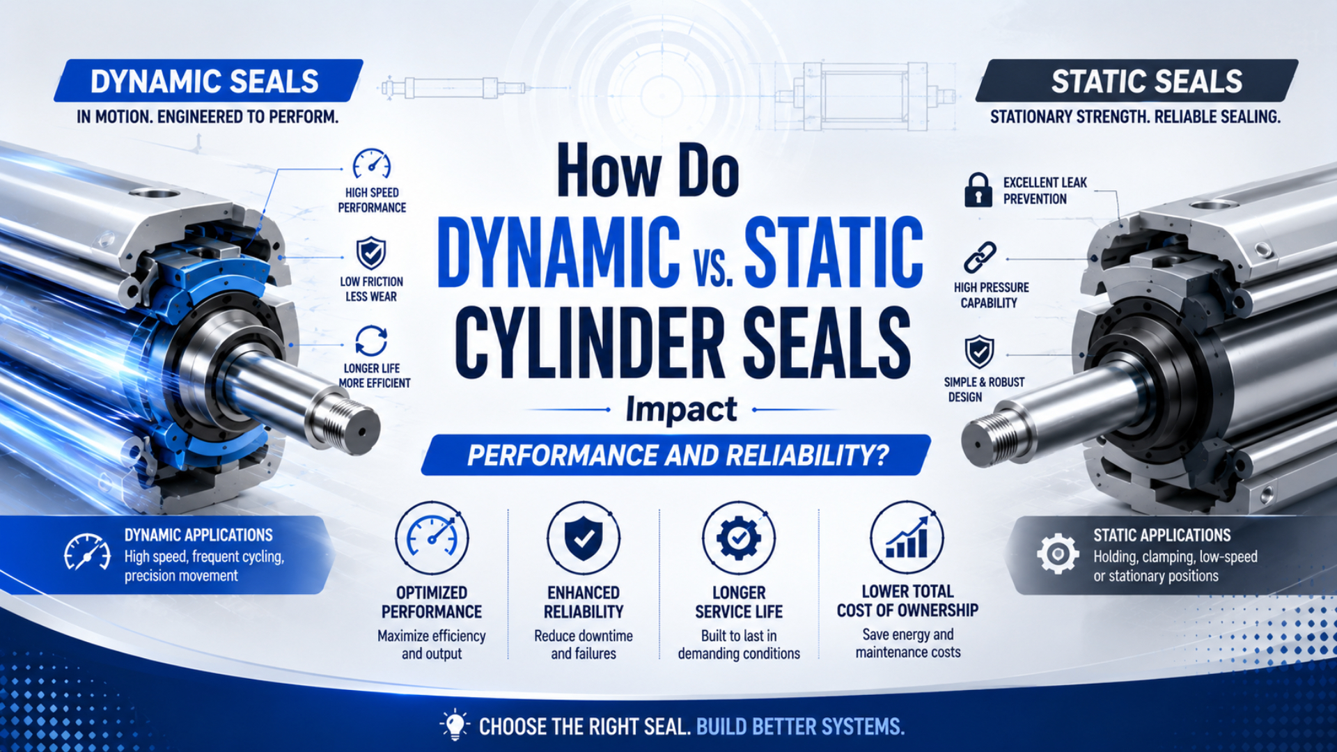
Phớt động của xi lanh làm việc với ty, piston, bàn trượt hoặc bề mặt quay đang chuyển động, nên thiết kế phải cân bằng khả năng chống rò với ma sát, bôi trơn, nhiệt và mài mòn. Phớt tĩnh của xi lanh làm kín mối ghép có các bề mặt tiếp xúc không chuyển động trong vận hành bình thường. Chính khác biệt về bề mặt làm việc này, chứ không phải màu sắc hay hình dạng chung, quyết định bài toán kỹ thuật.
Vòng O là ví dụ rõ ràng. Nó phổ biến ở mối ghép tĩnh, nhưng Parker vẫn công bố hướng dẫn riêng cho vòng O chuyển động tịnh tiến trong khí nén. Biên dạng phớt không mặc nhiên là tĩnh hay động. Rãnh, độ ép, bề mặt đối tiếp, hướng áp suất, tốc độ, vật liệu và bôi trơn phải phù hợp chuyển động thực tế.
Tóm tắt: Hướng dẫn khí nén của Parker chỉ cho phép độ nén theo chu vi từ 1% đến 3% đối với vòng O dùng làm phớt ty. Phạm vi hẹp, riêng theo sản phẩm này cho thấy rãnh động và rãnh tĩnh không thể dùng thay nhau. Trước hết hãy phân loại bề mặt làm việc, sau đó kiểm tra đường rò, ma sát, tình trạng bề mặt, dẫn hướng, vật liệu và bằng chứng thử nghiệm.
Phớt động và phớt tĩnh nằm ở đâu bên trong xi lanh?
Trelleborg chia phần tử làm kín khí nén thành 6 nhóm chức năng: phớt ty, phớt piston, cụm phớt ty/phớt gạt, phớt tĩnh, phớt gạt và phần tử chịu mòn hoặc giảm chấn. Câu trả lời thực tế dựa trên vị trí: bề mặt ty và piston chuyển động là động, còn mối ghép nắp đầu, cổng và ống xi lanh thường là tĩnh (Phớt khí nén Trelleborg, truy cập năm 2026).
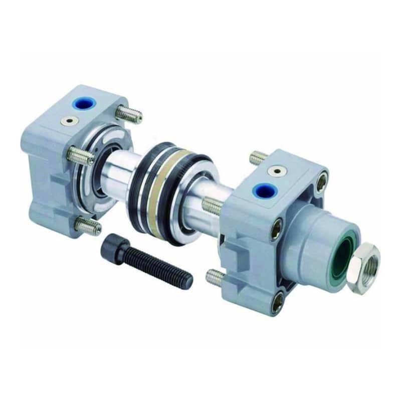
Bốn vùng bề mặt sau bao quát hầu hết xi lanh khí nén có ty:
| Vùng bề mặt | Chuyển động tương đối khi vận hành | Bộ phận chính | Rò rỉ hoặc hư hỏng cần theo dõi |
|---|---|---|---|
| Ống xi lanh với nắp đầu, cổng, vít giảm chấn | Không | Vòng O tĩnh hoặc gioăng | Rò ra ngoài tại mối ghép cố định |
| Piston với lòng xi lanh | Tịnh tiến qua lại | Phớt piston động | Lọt khí giữa hai buồng, lực yếu, trôi vị trí |
| Ty với đầu hoặc nắp dẫn hướng | Tịnh tiến qua lại | Phớt chịu áp động của ty | Rò khí ra môi trường tại đầu ty |
| Cửa vào ty và dẫn hướng piston | Tiếp xúc tịnh tiến nhưng chức năng khác nhau | Phớt gạt và vòng chịu mòn | Bụi bẩn xâm nhập, mòn một phía, xước |
Phớt gạt và vòng chịu mòn phải được gọi riêng. Phớt gạt ngăn bụi, ẩm, phoi hoặc cặn rửa lọt tới phớt ty. Vòng chịu mòn dẫn hướng cụm chuyển động và chịu phản lực ngang cho phép. Không bộ phận nào mặc nhiên là phớt chịu áp chính.
Điều này quan trọng thế nào khi sửa chữa? Tiếng khí ở đầu ty chỉ tới một bề mặt khác với khí lọt trong giữa hai buồng. Thay mọi vòng polymer màu đen như một “bộ phớt” không phân biệt có thể che khuất đường hư hỏng ban đầu.
Để xem thêm biên dạng và ứng dụng, hãy đọc hướng dẫn các loại phớt xi lanh công nghiệp. Bài này tập trung vào bề mặt chuyển động và bằng chứng cần để chẩn đoán.
Câu hỏi đầu tiên hữu ích nhất không phải “Tôi cần loại cao su nào?” mà là “Hai bề mặt nào chuyển động tương đối với nhau khi xi lanh chạy?” Câu hỏi đó phân tách rò mối ghép cố định, lọt khí qua piston, rò đầu ty và hư hỏng dẫn hướng trước khi bắt đầu chọn vật liệu.
Cùng một vòng O có thể vừa làm phớt tĩnh vừa làm phớt động không?
Có, nhưng quy tắc lắp đặt thay đổi. Sổ tay vòng O khí nén của Parker cho phép độ nén chu vi từ 1% đến 3% khi làm phớt ty và độ giãn đường kính trong tới 6% khi dùng cho piston. Đây là giá trị riêng theo thiết kế, không phải cho phép chuyển vòng O của mối ghép tĩnh sang bất kỳ rãnh động nào (Sổ tay vòng O Parker, truy cập năm 2026).
Trong mối ghép tĩnh, độ ép có kiểm soát tạo ứng suất tiếp xúc lên các bề mặt cố định. Cần xem xét chủ yếu sự giãn ứng suất dài hạn, biến dạng dư nén, chu kỳ nhiệt, trương nở hóa học, tỷ lệ lấp đầy rãnh và hư hỏng lắp ráp. Vì không có trượt liên tục, ma sát khởi động và ma sát chạy không phải tổn thất vận hành thông thường.
Trong rãnh động, cùng loại vòng cơ bản đó có thể trượt, lăn, xoắn hoặc tạm thời mất màng bôi trơn. Thiết kế phải kiểm soát ma sát và mài mòn trong khi vẫn duy trì đủ ứng suất tiếp xúc để làm kín. Sổ tay Parker coi tốc độ, hướng áp suất, độ ép, hình dạng rãnh, nhiệt độ, chiều dài hành trình, độ nhám bề mặt, bôi trơn và vòng chống đùn là các biến liên kết.
Vậy kỹ thuật viên bảo trì có thể tạm dùng vòng O trong rãnh phớt ty không? Chỉ khi nhà sản xuất xi lanh hoặc nhà cung cấp phớt đủ năng lực xác nhận đúng biên dạng, hợp chất, kích thước, rãnh, bề mặt, áp suất, nhiệt độ, tốc độ và chất bôi trơn. Giống nhau bằng mắt không chứng minh khả năng làm việc động.
| Câu hỏi | Bề mặt tĩnh | Bề mặt động |
|---|---|---|
| Điều gì tạo khả năng làm kín? | Độ nén có kiểm soát tại mối ghép cố định | Ứng suất tiếp xúc được duy trì khi bề mặt chuyển động |
| Điều gì thường giới hạn độ tin cậy? | Biến dạng dư, lão hóa, trương nở, lấp đầy rãnh, vết cắt khi lắp | Ma sát, mòn, trượt giật, nhiệt, nhiễm bẩn, đùn khe, xoắn |
| Bề mặt nào quan trọng nhất? | Rãnh và các mặt đối tiếp cố định | Ty hoặc lòng xi lanh chuyển động cùng rãnh và mép dẫn vào |
| Bằng chứng thử nghiệm phải gồm gì? | Áp suất, môi chất, nhiệt độ, thời gian | Điều kiện tĩnh cộng tốc độ, hành trình, chu kỳ, bôi trơn, đảo chiều |
Trelleborg gọi vòng O là phớt tĩnh phổ biến nhất, nhưng định nghĩa vẫn dựa trên việc không có chuyển động giữa các bề mặt làm kín. “Phổ biến nhất” không có nghĩa “chỉ dùng tĩnh” (Phớt tĩnh Trelleborg, truy cập năm 2026).
Chuyển động thay đổi ma sát, rò rỉ, mài mòn và độ tin cậy thế nào?
Parker chia ma sát phớt động thành 2 trạng thái: ma sát thoát dính và ma sát chạy. Vì vậy, xi lanh có thể kín khi đứng yên nhưng chần chừ lúc bắt đầu chuyển động, hoặc chạy chấp nhận được sau khi thoát dính nhưng mòn nhanh. Độ tin cậy động là sự cân bằng giữa ứng suất tiếp xúc, màng bôi trơn, cấu trúc bề mặt, áp suất, độ thẳng hàng và nhiễm bẩn (Sổ tay vòng O Parker, truy cập năm 2026).
Độ dôi lớn hơn không mặc nhiên an toàn hơn. Độ ép tăng có thể cải thiện tiếp xúc tĩnh lúc đầu, nhưng làm tăng lực khởi động, nhiệt, mài mòn và nguy cơ xoắn trong rãnh tịnh tiến. Tiếp xúc quá ít có thể rò, nhất là ở áp suất thấp hoặc sau khi elastomer giãn ứng suất. Cửa sổ sử dụng phải lấy từ dữ liệu thiết kế của nhà sản xuất phớt đã chọn.
Độ hoàn thiện bề mặt cũng quan trọng. Ty thô có thể mài môi phớt. Lòng xi lanh hư hỏng có thể cắt phớt piston. Bề mặt không giữ được màng bôi trơn dự kiến có thể tăng trượt giật, còn vết xước theo đường rò có thể phá hỏng tiếp xúc. Không quy định một giá trị độ nhám chung khi chưa có dữ liệu đúng biên dạng và vật liệu.
Nếu phớt mới chỉ mòn một phía thì sao? Dạng này phải đưa độ thẳng hàng, tình trạng ty, khe hở ống lót, dẫn hướng piston và tải ngang lên trước độ cứng vật liệu trong cây sự cố. Phớt piston không phải bạc đỡ. Hướng dẫn hỏng bạc dẫn hướng và phớt ty giải thích chi tiết đường truyền tải này.
Theo kinh nghiệm của chúng tôi, cách kiểm tra nhanh nhất phải bảo toàn hướng. Chụp ảnh phớt trước khi vệ sinh, đánh dấu vị trí mặt đồng hồ khi xi lanh lắp trên máy, rồi so sánh độ mòn môi phớt với vết xước ty, vùng bạc bị đánh bóng, hướng tải và vị trí hành trình xảy ra kẹt. Rửa chi tiết trước có thể xóa bằng chứng này.
Khí khô hoặc nhiễm bẩn cũng làm thay đổi kết quả. Nếu có châm dầu ở thượng nguồn, đổi loại hoặc bỏ dầu có thể thay đổi đặc tính phớt. Hãy xem hướng dẫn bôi trơn khí và vật liệu phớt trước khi đổi chính sách bôi trơn của nhà máy, đồng thời kiểm tra giới hạn của phớt tự bôi trơn khi catalog dùng thuật ngữ này.
Which Failure Pattern Points to a Dynamic or Static Seal Problem?
ISO 19973-3 reports pneumatic cylinder reliability in 2 lifetime measures, cycles or kilometres, and evaluates first failure under declared test conditions. It doesn’t supply a universal replacement count. In the field, classify the leak path and physical evidence first, then compare the exact cylinder and seal kit with manufacturer limits (ISO 19973-3, confirmed 2021).
| Evidence | First interface to inspect | Don’t conclude yet |
|---|---|---|
| Bubbles or sound at an end cap, fitting, or cushion screw | Static joint, groove, seal cross-section, fastener condition | That every cylinder seal is worn |
| Air escaping at the rod end during a controlled test | Rod pressure seal, rod surface, gland, wiper | That the visible wiper is the pressure seal |
| Weak force, drift, or air passing between chambers | Piston seal, bore, piston guide, connected valve path | That external leakage must be present |
| Seal lip and bushing polished on the same side | Guidance, mounting, rod condition, side load | That harder material will correct alignment |
| Twisted or spiraled O-ring | Dynamic groove, squeeze, lubrication, stroke and pressure direction | That the compound alone caused the failure |
| Flattened, hardened, swollen, cracked, or nicked static seal | Temperature, medium, age, groove fill, assembly edge | That a universal calendar interval applies |
Troubleshooting must follow the machine’s energy-control procedure. Isolate all energy sources, secure suspended loads, release trapped pressure, and verify the safe state before disconnecting a port or opening a cylinder. Observation during a controlled cycle is different from hands-on disassembly.
If the leakage route remains uncertain, the internal cylinder leakage diagnostic provides a more detailed isolation sequence. Severe rod, bore, head, or guide damage may also shift the decision from a service kit to the repair-versus-replace framework.
What Specifications Control Dynamic and Static Seal Selection?
Trelleborg’s current pneumatic overview lists 6 functional groups, including rod seals, piston seals, combinations, static seals, scrapers, and wear or cushioning elements. That range shows why material is only one input. A useful specification identifies position, motion, pressure, speed, temperature, medium, surface, guidance, and installation constraints (Phớt khí nén Trelleborg, truy cập năm 2026).
Use the following sequence:
- Identify the interface and leakage direction. State whether the seal closes an end cap, separates piston chambers, retains pressure at the rod, excludes contamination, or supports guidance.
- Describe the motion. Include reciprocating or rotary motion, stroke, speed range, cycle profile, reversals, dwell time, and any vibration. “Dynamic” alone isn’t enough.
- Provide pressure conditions. Give normal regulated pressure, minimum pressure where sealing matters, transients, pressure direction, exhaust back pressure, and vacuum conditions if applicable.
- Define the environment. Record minimum and maximum temperature, compressed-air quality, added lubricant, cleaning chemicals, washdown, particles, moisture, and outdoor exposure.
- Inspect the mating hardware. Provide groove dimensions, rod or bore diameter, lead-in geometry, surface condition, damage, material, coating, alignment, and guide clearance.
- Confirm regulatory status by compound. Food-contact suitability is tied to the exact substance, manufacturer, intended use, and conditions, not a generic claim that every EPDM or silicone seal is “FDA approved” (FDA Food Contact Status, updated 2024).
- Request product-specific evidence. Ask for the drawing revision, compound designation, operating limits, installation instructions, compatibility basis, traceability, and test conditions behind any service-life claim.
Which input is easiest to miss? Minimum pressure. A pressure-energized lip or floating piston arrangement may behave differently during start-up, exhaust, low-pressure motion, or long dwell than it does at normal supply pressure. Specify the whole duty profile, not just the regulator’s maximum setting.
Static and dynamic selection should share one document but use different acceptance evidence. A static joint review emphasizes retained contact after temperature and aging. A dynamic review adds breakaway force, running friction, leakage across the travel, wear pattern, lubricant condition, and performance after reversals.
How Should Seal Life and Reliability Claims Be Validated?
ISO 19973-1 requires reliability test data to be tied to stated test conditions and statistical procedures, while Part 3 applies the method to rod cylinders. Therefore, “5 million cycles” is incomplete unless the cylinder, seal material, pressure, stroke, speed, environment, lubrication, sample count, failure threshold, and permitted maintenance are disclosed (ISO 19973-1, 2015).
Use cycle life as a conditional test result, not as a universal replacement interval. Two cylinders can record the same number of cycles while accumulating very different sliding distance, reversals, dwell time, temperature exposure, contamination, and side load. ISO 19973-3 even permits life to be reported in cycles or kilometres, reinforcing that duty description matters.
A defensible comparison should state:
- exact cylinder series, bore, stroke, rod, seal profile, and compound;
- normal and transient pressure, speed, cycle timing, load, and cushioning;
- compressed-air quality, lubricant policy, temperature, and contamination;
- sample quantity, preconditioning, inspection points, and allowed adjustment;
- leakage, friction, motion, wear, or damage threshold that defines first failure;
- whether the result is laboratory qualification, supplier validation, or field history.
Can one supplier’s test be used to rank every aftermarket kit? No. It supports only the tested configuration and declared boundaries. Compare like with like, then validate the replacement in the machine’s real duty cycle under an approved commissioning plan.
We’ve found that seal-kit requests are much easier to resolve when buyers send the cylinder model, bore, stroke, rod diameter, photos, failure location, and air conditions together. Color and loose-ring dimensions alone rarely identify the original compound, lip orientation, or the damaged mating surface.
Before ordering, send those configuration details along with cycle rate, speed, pressure, temperature, lubricant, cleaning chemicals, mounting, side load, and the evidence preserved during disassembly. That package supports a technical match instead of a visual guess.
Dynamic vs. Static Cylinder Seal FAQs
Parker’s pneumatic O-ring guidance uses a 1% to 3% circumferential-compression range for rod-seal applications, proving that a dynamic answer needs the actual gland. These 5 FAQs separate interface classification, emergency substitution, wipers, service intervals, and repeat leakage without assigning unsupported universal limits (Parker, truy cập năm 2026).
Is an O-ring always a static cylinder seal?
No. O-rings are common in fixed joints, but they can also operate in pneumatic reciprocating applications when the compound, groove, squeeze, stretch, speed, pressure, surface finish, and lubrication meet product-specific guidance. Parker publishes separate dynamic pneumatic O-ring dimensions, so classify the interface before classifying the ring.
Can a static O-ring temporarily replace a dynamic rod seal?
Only if the cylinder or seal manufacturer approves that exact O-ring and gland for dynamic service. Matching diameter and color isn’t enough. A rod application adds friction, wear, lead-in geometry, speed, lubrication, pressure direction, and surface-finish requirements that a static-joint spare may never have been designed to satisfy.
Is the rod wiper the same as the rod pressure seal?
Usually not. Trelleborg lists pneumatic scrapers and rod seals as separate categories, although combined profiles also exist. A wiper primarily excludes outside contamination; the rod pressure seal retains compressed air. Identify the installed profile and leakage path before deciding which component failed or ordering a replacement.
How often should dynamic and static cylinder seals be replaced?
Use manufacturer instructions, condition evidence, and a defined maintenance risk review rather than a universal calendar or cycle count. ISO 19973-3 reports cylinder life under declared conditions in cycles or kilometres. Leakage, friction, motion quality, contamination, surface damage, and test history should drive the actual interval.
Why does a new dynamic seal start leaking again?
The original cause may still be present. Check rod or bore scoring, wiper damage, guide clearance, misalignment, side load, contamination, lubricant changes, groove damage, wrong profile, and installation cuts. One-sided wear is especially useful because it connects seal damage with the direction of the mechanical load path.
Nguồn và tài liệu kỹ thuật
- Sổ tay vòng đệm O Parker, ORD 5700, nguyên lý thiết kế tĩnh và động, ma sát, mài mòn, vòng đệm O chuyển động tịnh tiến trong khí nén, rãnh, độ hoàn thiện bề mặt và bôi trơn; truy cập ngày 2026-07-19.
- Sổ tay vòng đệm O Parker, ấn bản châu Âu, hướng dẫn lắp vòng đệm O cho ty và piston khí nén; truy cập ngày 2026-07-19.
- Phớt khí nén Trelleborg, các dòng sản phẩm phớt ty, phớt piston, phớt tĩnh, phớt gạt, vòng chịu mòn và giảm chấn; truy cập ngày 2026-07-19.
- Phớt tĩnh Trelleborg, định nghĩa bề mặt tiếp giáp tĩnh và các dạng phớt thông dụng; truy cập ngày 2026-07-19.
- Danh mục sản phẩm Trelleborg, tháng 12 năm 2025, các nhóm phớt khí nén hiện hành; truy cập ngày 2026-07-19.
- ISO 19973-1:2015, quy trình chung để đánh giá độ tin cậy của linh kiện khí nén; xác nhận năm 2020, truy cập ngày 2026-07-19.
- ISO 19973-3:2015, thử độ tin cậy của xi lanh khí nén có ty piston; xác nhận năm 2021, truy cập ngày 2026-07-19.
- FDA, Xác định tình trạng pháp lý của các thành phần trong vật liệu tiếp xúc thực phẩm, tình trạng theo từng chất, nhà sản xuất, mục đích sử dụng và điều kiện cụ thể; cập nhật năm 2024, truy cập ngày 2026-07-19.