

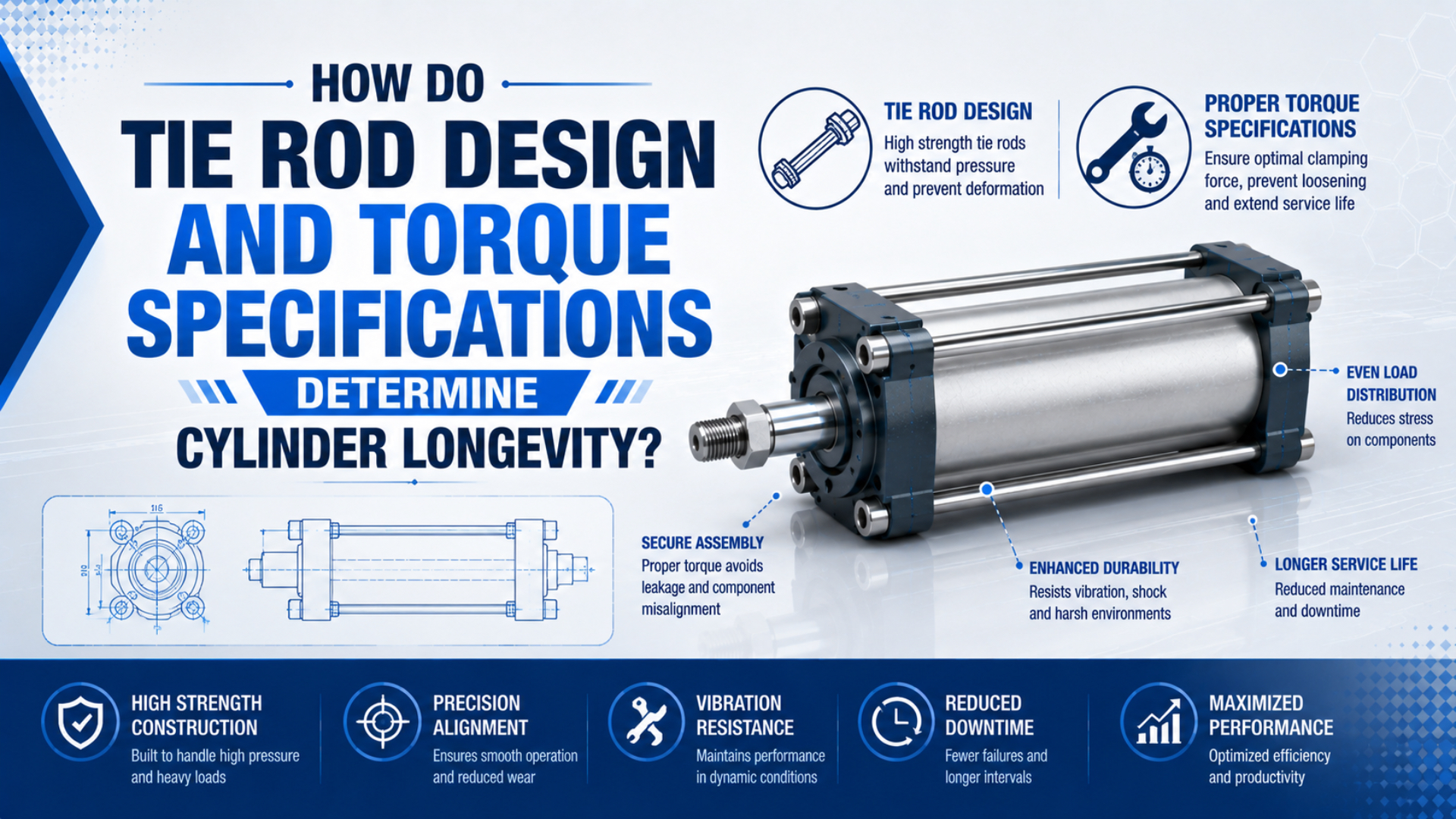
Tie rod design and torque specifications affect pneumatic cylinder life by keeping the end caps, tube, seals, and bearing features in a stable clamped assembly. Torque is the manufacturer’s controlled installation input for producing that joint. It is not a universal value that can be selected from bore size alone.
The practical rule is straightforward: use the complete cylinder model and its current repair instruction. Match the specified fasteners, lubrication or locking condition, tightening locations, sequence, tool, and acceptance test. If any of those inputs is unknown, retightening is an experiment on a pressure-containing assembly.
Key Takeaways
- ISO 15552 covers a 10 bar dimensional series, not universal tie-rod torque.
- Torque is only a proxy for preload because thread and bearing friction consume much of the input.
- One AVENTICS manual gives two different torque values for the same bore.
- Rebuild acceptance must include leakage and functional testing.
What Load Do Tie Rods Actually Carry?
Tie rods resist the separating load that internal pressure applies to the end-cap assembly, while the tube, end caps, seals, and fasteners form the complete joint. ISO 15552:2018 covers a 1,000 kPa, or 10 bar, dimensional series, but it does not prescribe one tie-rod design or torque table (ISO 15552).
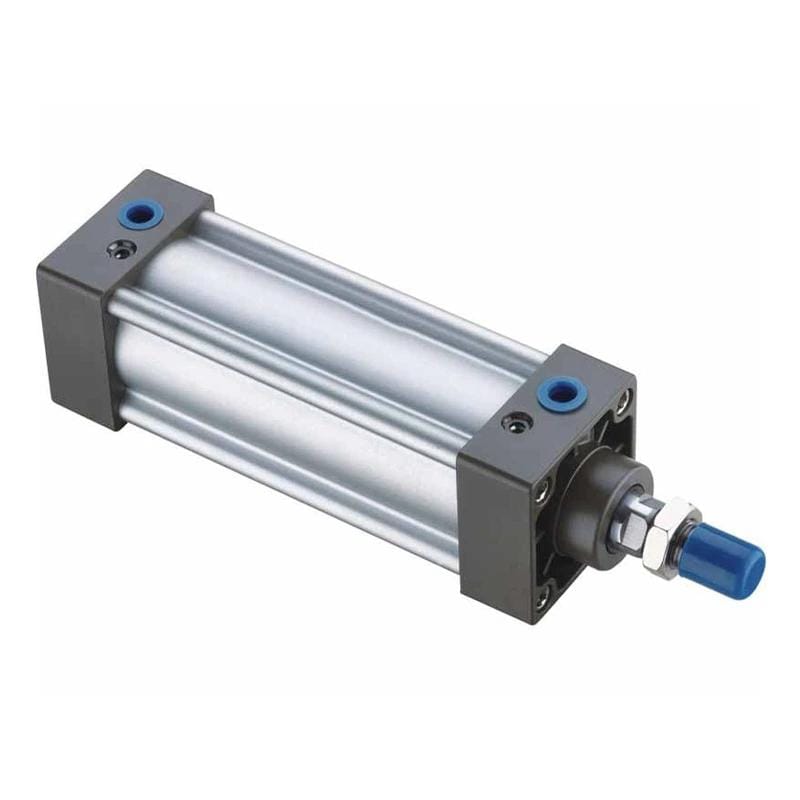
The exposed rods make the clamped construction visible, but the exact joint dimensions and tightening requirements remain model-specific.
The pressure force acting on a circular end-cap area can be screened with:
Here, is the ideal pressure-separating force in newtons, is internal gauge pressure in pascals, and is the effective pressurized diameter in metres. The equation assumes a circular pressure area and steady pressure. It does not calculate required tie-rod torque.
For and , the ideal separating force is . Pressure spikes, cushion events, joint stiffness, thread geometry, material limits, manufacturing tolerances, and the supplier’s safety factors still belong in the design review.
Why can’t that 4.71 kN simply be divided by four rods? A preloaded joint doesn’t distribute service load through arithmetic alone. The stiffness of the rods and clamped parts determines how much external load increases fastener tension and reduces compression at the joint interface. End-cap geometry and local bending also matter.
Seal compression is not always set directly by tie-rod tension. Many cylinders use grooves, shoulders, spigots, or tube stops that define the assembled geometry. Correct preload keeps those interfaces seated. It shouldn’t be described as an adjustable seal-squeeze control unless the drawing and manual establish that function.
For the broader construction choice, see the comparison of profile and tie-rod cylinders. That article addresses packaging and service architecture; this one addresses the integrity of an approved tie-rod joint.
Why Is Torque Only a Proxy for Tie-Rod Preload?
Torque is an installation input, while preload is the tensile force created in the tie rod. NASA RP-1228 shows calculated torque coefficients from 0.074 to 0.250 as the assumed friction coefficient changes from 0.05 to 0.20, so one torque cannot produce one predictable preload across unknown surface conditions (NASA Fastener Design Manual).
A common screening relationship is:
Here, is tightening torque in newton-metres, is a dimensionless torque coefficient, is fastener preload in newtons, and is nominal thread diameter in metres. The relationship is useful for understanding sensitivity. It is not permission to reverse-engineer an OEM torque specification from an assumed .
NASA warns that the commonly assumed should not be used blindly. Thread friction, nut or head bearing friction, coating, lubricant, prevailing torque, thread damage, reuse, and surface cleanliness all change the torque path. ISO 16047 formalizes torque/clamp-force testing for defined threaded-fastener conditions rather than treating torque as a universal material property (ISO 16047).
What happens if a dry specification is applied to a newly lubricated thread? Less torque may be lost to friction, so the same wrench reading can create more preload. The opposite can occur with corrosion, contamination, damaged threads, or an unaccounted self-locking feature. This is why “clean the threads and add anti-seize” can be a design change, not routine housekeeping.
Tie-rod preload is the tensile force intentionally established before the cylinder is pressurized. Installation torque is one indirect method for creating and controlling that force. Keep the terms separate in drawings, work instructions, inspection records, and failure reports.
Why Must Torque Values Come From the Exact Cylinder Manual?
The correct value belongs to the exact model, fastener location, and assembly condition. In one AVENTICS PRA/TRB instruction, a 63 mm cylinder uses 11 ± 1 N·m at location A and 19 ± 1.5 N·m at location B, even though both values appear in the same bore row (AVENTICS PRA/TRB Repair Instruction).
That manual covers seven bores from 32 to 125 mm. Its values change by bore and by the identified screw or nut. A 100 mm example uses 32 ± 3 N·m at A and 40 ± 3 N·m at B. Copying only “40 N·m for a 100 mm cylinder” would erase the location, tolerance, series, hardware, and assembly instruction that make the number meaningful.
Use this evidence hierarchy:
-
Exact current repair instruction: series, bore, revision, fastener locations, sequence, torque, tolerance, lubricant, locking compound, and replacement rules.
-
Configured drawing and bill of material: tie-rod or screw code, nut, washer, thread, material, coating, grip length, and end-cap interface.
-
Controlled deviation: an engineering-approved process supported by torque/clamp-force testing, inspection, and acceptance evidence.
-
Generic table: screening information only. It cannot release a repaired pressure assembly.
ISO 15552 standardizes basic, mounting, and accessory dimensions across 32 to 320 mm bores. It doesn’t standardize every port, seal, tube, tie rod, end cap, repair method, or tightening value. The ISO 15552 interchangeability guide explains the same boundary for replacement selection.
Failure Evidence: Too Little, Too Much, or Uneven Preload
Failure evidence must be interpreted as a joint system, not as a torque reading alone. ISO 16047 applies torque/clamp-force testing to defined fasteners from M3 to M39 within its stated scope, reinforcing that thread size, hardware, friction condition, and test method must be controlled before preload conclusions are drawn (ISO 16047).
| Finding | Possible joint explanation | Other causes to exclude |
|---|---|---|
| Leakage at an end-cap interface | Insufficient clamp retention, uneven seating, damaged static seal | Wrong seal, cut seal, dirty groove, scratched face, loose fitting |
| Fretting or polished movement marks | Relative motion at a clamped interface | External vibration, poor mounting, contamination during assembly |
| One loose nut or tie rod | Uneven tightening, thread damage, embedment, loss of locking function | Incorrect hardware, impact damage, unauthorized adjustment |
| High breakaway force or binding | Distorted or misaligned assembly | Side load, bent rod, damaged bearing, dry seals, scored tube |
| Damaged threads or yielded fastener | Excess preload, cross-threading, wrong nut, repeated reuse | Corrosion, prior impact-tool damage, incompatible materials |
| Unequal end-cap gap | Incomplete seating or uneven joint loading | Debris, incorrect tube length, displaced seal, damaged locating feature |
Too little preload can allow a clamped interface to unload, move, fret, or leak under pressure cycling. Too much preload can overload the threaded parts or bearing faces and may distort a compliant end cap or tube interface. Uneven preload can tilt the end cap or concentrate load. None of those conclusions should be made from leakage alone.
In our experience, witness marks are more useful than a maintenance note that says “loose.” Record nut position, end-cap gaps, corrosion, thread condition, lubricant, seal orientation, and breakaway behavior before disassembly. A calibrated removal-torque reading can be recorded as evidence, but it is not the original installed preload.
If binding or repeat seal wear is present, also investigate side loading and the complete pneumatic cylinder sealing system. Tightening a mechanically misaligned cylinder won’t correct its load path.
A Seven-Step Tie-Rod Cylinder Reassembly Workflow
A controlled rebuild starts with product-specific instructions. The AVENTICS PRA/TRB document covers seven bores, requires depressurization, calls for a torque spanner, specifies supplied grease on cleaned seal positions, and provides separate A and B tightening values (AVENTICS PRA/TRB Repair Instruction).
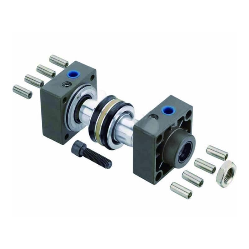
An exploded assembly exposes several interfaces that must be identified, cleaned, inspected, lubricated, oriented, and tightened according to the exact repair instruction.
-
Control hazardous energy. Follow the machine’s energy-control procedure, isolate the air supply, bleed stored pressure, restrain gravity or spring loads, and verify isolation. OSHA 29 CFR 1910.147 explicitly includes pneumatic energy in its definition of an energy source (OSHA 1910.147).
-
Confirm identity and documents. Record the complete cylinder code, bore, stroke, revision, repair-kit number, drawing, manual revision, torque locations, units, tolerances, and specified lubricant or locking product.
-
Preserve the as-found condition. Mark orientation, photograph end-cap gaps and nut positions, and record leakage, binding, corrosion, contamination, and failed direction. Don’t clean away the evidence first.
-
Inspect every load-path part. Check tie rods, screws, nuts, threads, washers, end caps, tube ends, locating shoulders, seal grooves, rod, bearings, and mounting interfaces against manufacturer limits. Replace parts when the manual requires single use or when condition is unacceptable.
-
Prepare the specified friction condition. Clean and lubricate only as instructed. Don’t add oil, anti-seize, threadlocker, plated nuts, or replacement washers unless they are approved for that joint. The torque value depends on this condition.
-
Seat and tighten by the approved method. Install seals and components in the correct orientation. Run fasteners down without forcing misaligned parts. Use the specified order, stages, cross-pattern, torque, angle, or other method only when the manual calls for it.
-
Verify and record. Use a suitable torque tool with current calibration status. ISO 6789-2:2017 describes calibration and uncertainty determination for hand torque tools (ISO 6789-2). Record tool ID, setting, units, date, operator, fastener location, and any approved deviation.
How Should You Accept the Rebuilt Cylinder?
Acceptance must test the complete function after assembly. ISO 10099:2001 specifies final functional tests and acceptance criteria for double-acting, single-rod pneumatic cylinders, a narrower scope than every tie-rod design but a useful framework for documented release (ISO 10099, confirmed 2023).
Build the acceptance sequence before disassembly so the repair team knows what must pass:
| Acceptance stage | Evidence to record | Typical stop condition |
|---|---|---|
| Identity review | Cylinder, repair kit, fasteners, manual, lubricant, tool ID | Any untraceable or mismatched part |
| Visual and dimensional check | End-cap seating, gaps, orientation, rod and port condition | Uneven seating, damaged thread, displaced seal |
| Controlled pressurization | Test pressure and method from manufacturer, external leakage | Leakage, abnormal movement, pressure instability |
| No-load cycling | Stroke, speed, sound, breakaway, cushions, sensors | Binding, impact, drift, missed sensor position |
| Application test | Load, dynamic pressure, stroke time, alignment, machine quality | Stall, excessive impact, temperature rise, product defect |
| Follow-up inspection | Agreed cycles, travel or hours, leakage and nut witness marks | Worsening trend or repeated movement evidence |
Don’t invent a pressure multiplier such as “test at four times working pressure.” The product manual, applicable standard, site procedure, and lowest-rated component must define the test. A repaired cylinder also needs guarding and a controlled test state so a seal, fitting, mount, or load failure doesn’t expose personnel.
Should every cylinder be retorqued after 24 to 48 hours? Not unless the manufacturer or an approved site procedure requires it. Routine retightening can hide damaged threads, joint movement, incorrect friction conditions, or an assembly error. Use witness marks and measured performance as inspection evidence, then escalate unexplained movement.
Connect recurring leakage or irregular motion to the pneumatic cylinder fault tree rather than assuming every post-repair symptom is a tie-rod problem.
When Should You Replace Instead of Retorque?
Retorque only when the cylinder is repairable, the correct data exists, and every load-path part passes inspection. ISO 15552 covers 11 nominal bores from 32 through 320 mm, yet its dimensional scope supplies no universal field-repair limit, reuse rule, or tightening value (ISO 15552).
Replace the cylinder or send it to a qualified repair facility when:
- the exact model, manual, torque locations, units, or friction condition cannot be established
- a tie rod, screw, nut, thread, washer, end cap, or tube shows unacceptable deformation, cracking, corrosion, galling, or material loss
- the barrel, locating diameter, sealing face, groove, rod, or guide is outside the manufacturer’s repair limit
- fasteners of unknown material, coating, property class, length, or thread have been substituted
- repeated tightening has not corrected the cause of leakage or joint movement
- the repair kit or specified hardware is obsolete or untraceable
- the cylinder cannot be isolated, assembled cleanly, or tested to defined acceptance criteria
- the application is safety-related, locked, braked, hygienic, cleanroom, custom, or otherwise outside the available repair instruction
Torque availability is part of repairability. A cylinder that can be physically opened isn’t automatically serviceable. Without traceable parts, friction conditions, tightening data, and an acceptance method, the plant can’t prove that the rebuilt joint matches the design state.
Use the repair-versus-replace assessment when deciding whether parts availability, downtime, test capability, and failure consequence support field work. For recurring programs, integrate the decision into the pneumatic actuator maintenance checklist.
The final rule is simple. Don’t tighten by bore, appearance, or habit. Restore the documented joint, verify the complete cylinder, and retain evidence that another qualified technician can reproduce.
Tie Rod Design and Torque Specifications FAQs
The AVENTICS PRA/TRB repair instruction covers seven bores from 32 to 125 mm and gives two location-specific torque columns, while NASA documents torque coefficients from 0.074 to 0.250 under different friction assumptions. These FAQs explain why identity, friction condition, controlled tooling, and functional acceptance must stay connected.
Can tie-rod torque be calculated from cylinder bore alone?
No. Bore and pressure can estimate the ideal end-cap separating force, but torque also depends on tie-rod diameter, thread, material, coating, nut interface, lubricant, joint stiffness, target preload, and safety factors. AVENTICS publishes different A and B torque values within the same bore row, proving that bore alone is insufficient.
Should tie rods be retorqued after the first 24 to 48 hours?
Only when the exact manufacturer instruction or an approved engineering procedure requires it. No universal 24-to-48-hour rule applies to every pneumatic cylinder. If witness marks move, leakage appears, or an end-cap gap changes, isolate the machine and investigate the joint rather than repeatedly adding torque without identifying the cause.
Can tie rods, nuts, and washers be reused after a cylinder repair?
Follow the exact parts and repair instruction. Reuse depends on the fastener design, material, coating, locking feature, thread condition, corrosion, prior loading, and manufacturer rule. Reject any part outside its inspection limit. Unknown hardware should not be returned to a pressure assembly merely because its thread fits.
Can an impact wrench be used on pneumatic cylinder tie rods?
Don’t use an impact wrench as an uncontrolled substitute for the specified final-tightening method. The AVENTICS PRA/TRB instruction calls for a torque spanner, while other products may define a different controlled process. Tool approval, rundown method, final torque, units, tolerance, sequence, and calibration must all come from the applicable work instruction.
Does equal torque on every nut guarantee equal tie-rod preload?
No. NASA shows torque coefficient values ranging from 0.074 to 0.250 as friction assumptions change. Equal wrench readings can therefore produce different preload when threads, bearing faces, coatings, lubrication, damage, or prevailing torque differ. Control the hardware and friction condition, then inspect seating and complete-cylinder function.
Sources and technical references
-
ISO 15552:2018, 10 bar pneumatic cylinder dimensional series. Confirmed 2025; retrieved 2026-07-19.
-
AVENTICS PRA/TRB Spare Kit Repair Instruction R413000908. Retrieved 2026-07-19.
-
NASA RP-1228, Fastener Design Manual. 1990; retrieved 2026-07-19.
-
ISO 16047:2005, Fasteners, torque/clamp-force testing. Confirmed; retrieved 2026-07-19.
-
ISO 6789-2:2017, Hand torque-tool calibration and measurement uncertainty. Retrieved 2026-07-19.
-
ISO 10099:2001, Pneumatic cylinder final examination and acceptance criteria. Confirmed 2023; retrieved 2026-07-19.
-
OSHA 29 CFR 1910.147, Control of hazardous energy. Retrieved 2026-07-19.