

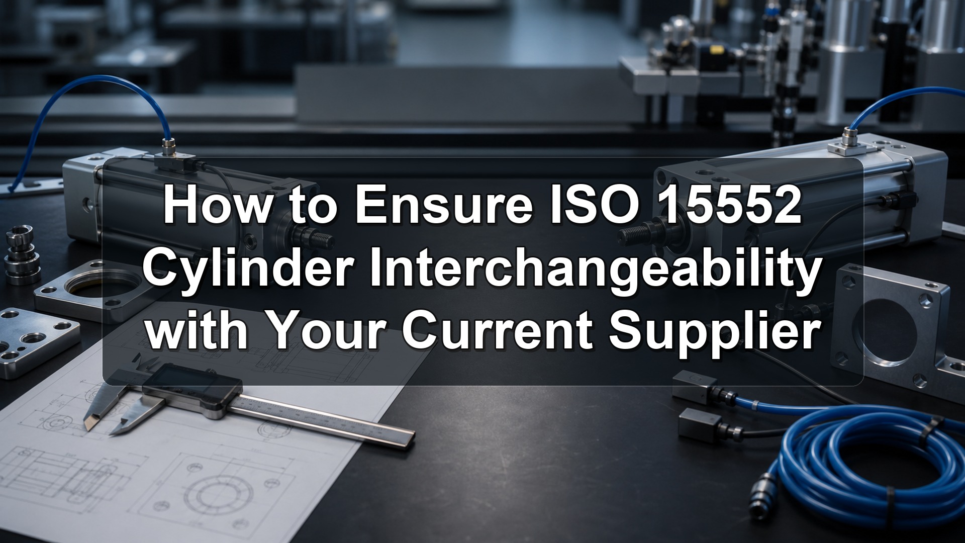
ISO 15552 cylinder interchangeability means more than finding the same bore and stroke on two datasheets. Approve a replacement only after its standardized mounting envelope, selected ports and rod end, sensing and cushioning configuration, application performance, and first-article test results all match the installed requirement.
ISO 15552:2018 covers detachable-mount pneumatic cylinders from 32 to 320 mm bore with a maximum rated pressure of 1,000 kPa, or 10 bar. It standardizes basic, mounting, and accessory dimensions needed for interchangeability, but it does not make every catalog option functionally identical (ISO 15552:2018, confirmed 2025).
Use current ISO pages, option-specific manufacturer data, and a two-supplier catalog comparison before declaring an ISO 15552 cylinder interchangeable. Unsupported tolerances, dimensional tables, percentages, or cost stories should not drive the replacement decision.
Key Takeaways
- ISO 15552 covers 32-320 mm bores at 10 bar as a dimensional interface (ISO 15552).
- Compare exact supplier configurations, not only bore and stroke.
- Approve fit, pneumatic interfaces, functional duty, and first-article results separately.
- Freeze the accepted drawing, part code, test record, and golden sample under change control.
The safest cross-reference is an interface ownership matrix. Mark each requirement as controlled by ISO 15552, the supplier’s configured drawing, or the machine acceptance test. That single distinction prevents an ISO label from being used as evidence for features the dimensional standard never promises.
Short Answer: Approve Four Layers, Not One Label
ISO 15552 defines a 32-320 mm dimensional series, while ISO 10099 provides final examination and acceptance criteria for double-acting, single-rod pneumatic cylinders (ISO 15552:2018; ISO 10099:2001, confirmed 2023). Use those scopes as separate evidence layers: standardized fit and tested function.
Approve the replacement at four levels:
| Approval layer | Question | Minimum evidence | Release condition |
|---|---|---|---|
| 1. Dimensional fit | Will the cylinder and detachable mounting fit the machine? | ISO family, supplier drawing, CAD overlay, measured first article | All drawing-controlled interfaces match |
| 2. Configured interfaces | Will existing fittings, rod hardware, sensors, and accessories connect? | Complete part-code decoder and option-specific datasheet | Every installed interface is accounted for |
| 3. Functional equivalence | Will it deliver the required motion in the real application? | Force, speed, cushioning, leakage, environment, duty data | Application limits and test criteria pass |
| 4. Validated release | Can purchasing reorder the same approved configuration? | First-article report, machine trial, revision record, golden sample | Exact configuration is frozen under change control |
This protocol is narrower than facility-wide pneumatic cylinder standardization. It is designed for one installed position and one proposed cross-supplier replacement.
Dimensional interchangeability is the ability to install the proposed cylinder through the standardized and drawing-controlled mechanical interfaces. Functional equivalence is the ability of that exact configured cylinder to meet the machine’s force, timing, cushioning, sensing, environmental, and safety acceptance criteria.
What Does ISO 15552 Actually Standardize?
The official title states that ISO 15552 covers basic, mounting, and accessory dimensions for detachable-mount cylinders rated up to 1,000 kPa, or 10 bar, across 32-320 mm bores (ISO 15552:2018). Its interchangeability promise is therefore dimensional and scoped, not a blanket guarantee of identical behavior.
The standard applies to single-rod and double-rod cylinders, with or without provisions for magnetic sensors. It is the correct reference for the cylinder envelope and specified detachable mounting interfaces. It does not remove the need to select a particular seal system, cushioning method, piston magnet, rod-end option, port configuration, temperature range, corrosion treatment, or sensor.
That boundary matters in purchasing language. A useful requirement is: “Cylinder basic and detachable mounting interfaces shall conform to ISO 15552:2018; all configured interfaces and performance requirements shall match the approved specification.” A vague line such as “ISO cylinder, 50 x 200” leaves too much unresolved.
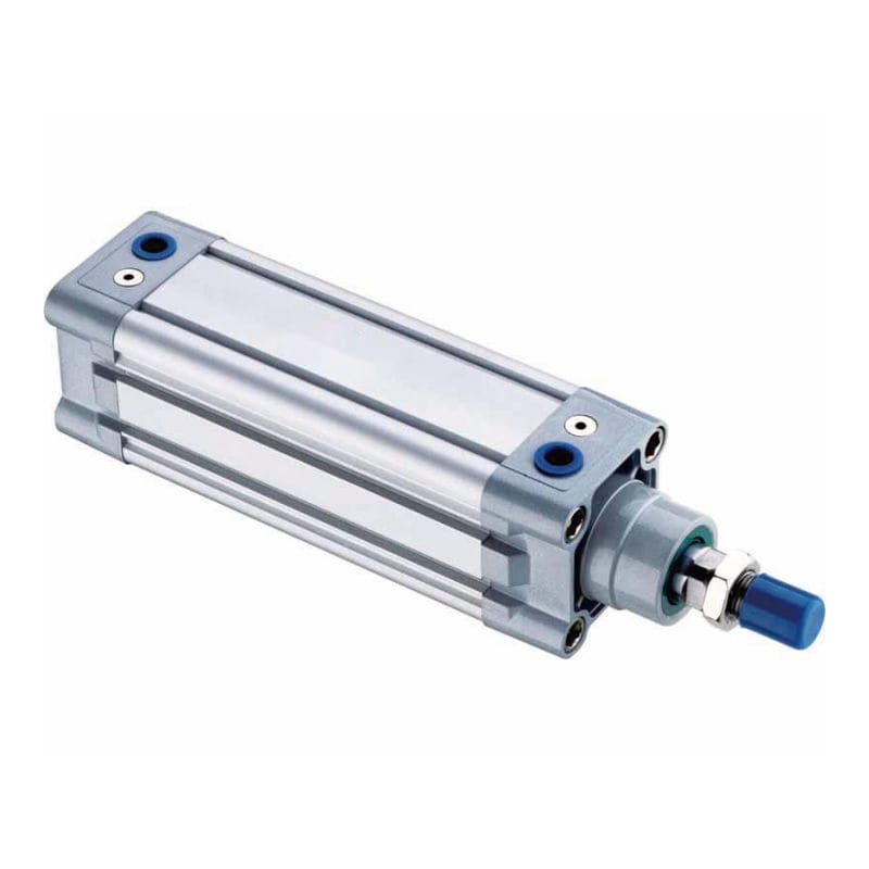
View an ISO 15552 tie-rod cylinder configuration
Do not copy unsourced tolerance values from a reseller table. The ISO product page does not publish the controlled dimensional tables, and the standard itself is copyrighted. Obtain the applicable standard, then compare its named dimensions against the current, option-specific supplier drawing.
Which Dimensions Must Match Across Supplier Drawings?
ISO 15552 includes 11 nominal bores from 32 through 320 mm, but a replacement decision also depends on stroke, installed length, mounting style, and accessory interfaces (ISO 15552:2018). Compare the complete configured drawings at the same bore, stroke, mounting code, and rod arrangement before measuring a sample.
Use a transparent CAD overlay or a controlled comparison sheet. At minimum, check:
- mounting hole pattern, threads, counterbores, and locating features
- cylinder centerline relative to the mounting surface
- retracted and extended overall lengths at the ordered stroke
- piston rod diameter, thread, usable thread length, and wrench flats
- front and rear accessory interfaces, including pins and clevis widths
- port thread, size, location, access, and required sealing method
- sensor slot or bracket location and cable clearance
- cushion-adjuster access and surrounding service clearance
Do not invent a universal tolerance such as “all mounting holes within 0.2 mm.” The pass limit should come from the ISO table where applicable, the approved machine drawing, the supplier’s controlled drawing, or a justified assembly requirement. Record the source beside every critical characteristic.
| Characteristic | Requirement owner | Evidence to compare | First-article check |
|---|---|---|---|
| Standard mounting envelope | ISO 15552 | Standard plus configured drawings | Measured critical dimensions |
| Stroke and installed length | Machine specification | Existing and proposed drawings | Retracted and extended measurement |
| Rod-end connection | Supplier configuration and machine | Part code, thread callout, mating hardware | Thread gauge or verified mating part |
| Port interface | Supplier configuration and site standard | Port callout, sealing specification, fitting | Correct gauge and leak-free assembly |
| Sensor and cushion access | Machine layout | CAD overlay and option drawing | Physical access and adjustment test |
If the installed cylinder is not ISO 15552, do not force it into this process. For small-bore round cylinders, use the ISO 6432 replacement workflow and its dimensional scope instead.
Are Ports, Rod Ends, Sensors, and Cushions Interchangeable?
Two current 50 mm ISO 15552 families illustrate the problem: SMC’s CP96 catalog and Festo’s DSBC data both list a G1/4 port and M16 x 1.5 male rod thread, yet their available strokes and cushioning configurations differ (SMC CP96 catalog; Festo DSBC data).
That is configuration equivalence, not merely dimensional compliance. Confirm each item against the exact order code:
| Interface | Why the ISO label is insufficient | What must match |
|---|---|---|
| Pressure port | A cylinder family may have regional or configured port variants | Thread designation, size, seal, orientation, fitting clearance |
| Rod end | Male and female versions may exist | Thread, gender, usable engagement, jam nut, mating accessory |
| Position sensing | Magnet and sensor provision may be optional | Magnet present, sensor type, voltage, output, connector, mounting position |
| Cushioning | Elastic, self-adjusting, and manually adjustable designs behave differently | Cushion type, adjustment access, moving mass, speed, residual impact |
| Materials and seals | Catalog families include temperature and corrosion variants | Seal material, lubricant, rod and fastener materials, temperature range |
ISO 228-1 defines parallel pipe threads where pressure-tight joints are not made on the threads (ISO 228-1:2000, confirmed 2022). ISO 1179-1 covers ports that use ISO 228-1 threads with specified sealing arrangements (ISO 1179-1:2013). Neither standard proves that every ISO 15552 cylinder uses one universal port configuration.
The SMC and Festo comparison exposes a useful procurement rule: even when a 50 mm cylinder shares G1/4 ports and an M16 x 1.5 rod thread, the part-code suffixes remain approval-critical. Standardized connection points do not standardize the options behind those connection points.
How Do You Prove Functional Equivalence?
SMC lists 50-1,000 mm/s piston speed and 0.05-1.0 MPa operating pressure for its CP96, while ISO 10099 covers final functional examination of double-acting, single-rod pneumatic cylinders (SMC CP96 catalog; ISO 10099:2001). Functional equivalence therefore needs application calculations plus a test plan.
Start with the operating point, not the nameplate maximum:
- Record pressure at the cylinder during motion, not only the regulator’s no-flow setting.
- Calculate theoretical extension and retraction force from bore, rod diameter, and measured pressure.
- Apply a justified allowance for friction, acceleration, pressure loss, load variation, and safety requirements.
- Confirm required stroke time, flow capacity, tubing, valve, and flow-control settings.
- Check moving mass, speed, and residual energy against the selected cushioning data.
- Verify side load, alignment, ambient temperature, contamination, washdown, corrosion, and duty cycle.
At 50 mm bore and 6 bar, theoretical extension force is about 1,178 N before losses. That calculation does not prove usable force or acceptable impact. Use it to expose assumptions, then verify the real motion. Our pneumatic cylinder force formula guide explains the pressure-area relationship, while the force calculation example covers practical deductions.
The installed machine test should observe full stroke, loaded stroke time, end impact, cushion adjustment range, sensor repeatability, leakage, binding, and safe behavior after energy isolation. If any acceptance criterion is not measurable, rewrite it before ordering.
What Supplier Documents Are Sufficient?
ISO 15552 spans 11 nominal bores from 32 to 320 mm, while ISO 9001 specifies a quality management system rather than product-specific interchangeability (ISO 15552:2018; ISO 9001). A supplier certificate cannot replace option-controlled drawings, performance data, inspection evidence, traceability, and a recorded cross-reference.
Request the following for the exact offered part number:
- a complete order-code breakdown, including all suffixes and regional variants
- a current 2D drawing and, where useful, a neutral 3D CAD model
- port, rod-end, sensor, cushioning, mounting, and accessory specifications
- rated pressure, operating temperature, media, speed, and cushioning limits
- materials and seal information for environment-sensitive applications
- the supplier’s declaration of ISO 15552 conformance, if claimed
- first-article dimensional and functional inspection results
- manufacturing location, batch or serial traceability, drawing revision, and change-notification terms
Use three document statuses: received, verified, and accepted. “Received” only proves that a file exists. “Verified” means its values were compared with the requirement. “Accepted” means the responsible engineer approved the evidence and recorded the revision.
| Document | Verification question | Reject or clarify when |
|---|---|---|
| Configured drawing | Does it represent the exact order code and stroke? | It is a generic family outline |
| Part-code decoder | Can every suffix be mapped to a feature? | Regional or optional codes are unexplained |
| Performance data | Does it cover the actual pressure, speed, load, and cushion? | Only maximum ratings are shown |
| Inspection report | Are measured results tied to the submitted sample? | Values are copied from nominal drawings |
| Change agreement | Will relevant changes be disclosed before shipment? | Revision and plant changes are unrestricted |
A supplier quotation should reference the accepted specification revision. For a complex RFQ, attach the comparison sheet rather than hiding requirements in an email thread.
How Should a First Article Be Inspected and Tested?
ISO 10099 is only four pages but establishes a dedicated final-examination and acceptance scope for double-acting, single-rod pneumatic cylinders (ISO 10099:2001). Build the first-article plan around that functional intent, then add the critical dimensions, interfaces, environment, and machine behavior specific to the installed position.
Use a five-gate release:
Gate 1: Confirm identity and documents
Photograph the nameplate, packaging label, part code, and included accessories. Match them to the purchase order and the supplier’s controlled drawing. Record serial or batch identity where available.
Gate 2: Inspect critical characteristics
Measure only after the drawing comparison has identified what is critical. Record the measuring instrument, calibration status, result, requirement source, and disposition. Use thread gauges or known mating hardware for ports and rod ends instead of visual judgment.
Gate 3: Run a bench functional examination
Apply clean compressed air within the supplier’s stated range. Check full stroke, smooth operation, leakage, cushioning response, sensor operation, adjustment access, and abnormal sound. Define test pressure, dwell, cycles, leakage method, and pass criteria before the sample arrives.
Gate 4: Validate on the machine
Install the sample with production fittings, sensors, mountings, guards, and controls. Test at representative low, normal, and credible high load conditions. Record dynamic pressure, stroke time, end impact, sensor switching, alignment, and any commissioning changes.
For U.S. workplaces, control hazardous energy during installation and servicing under the applicable energy-control procedure. OSHA 29 CFR 1910.147 covers the control of hazardous energy during servicing and maintenance (OSHA 1910.147).
Gate 5: Freeze the accepted configuration
Approve the exact part code, drawing revision, accessory list, test record, and any permitted substitutions. Label and retain a golden sample when the replacement risk justifies it. Link the record to the machine position and purchasing cross-reference.
A golden sample is useful only when it represents an accepted configuration, not merely a cylinder body. Store its sensor, mounting, rod accessory, fitting assumptions, and drawing revision with it. Otherwise, future inspections can match the sample physically while missing a changed order-code suffix.
Supplier Change Control and the Golden Sample
SMC’s CP96 catalog separates six bores from 32 to 100 mm and numerous mounting and sensor choices, showing how many configurations can sit inside one ISO family (SMC CP96 catalog). Set change control and monitoring frequency from configuration risk, supplier performance, criticality, and incoming evidence.
Your supplier agreement should define which changes require prior notice. Examples include manufacturing location, drawing revision, material, seal compound, lubrication, magnet, sensor, machining process, critical sub-supplier, test method, and labeling. Not every change affects interchangeability, but the supplier should not decide that alone for a critical approved part.
Use risk-based incoming control:
- verify every shipment’s part code, revision, quantity, and visible configuration
- sample critical dimensions and functional behavior at a frequency justified by risk and performance
- increase inspection after a change, deviation, complaint, or unexplained drift
- reduce inspection only when evidence supports it and the approval owner agrees
- revalidate on the machine when a change can affect fit, motion, sensing, cushioning, or environment
Track replacement-fit failures separately from general defects. A cylinder can be well manufactured and still be the wrong approved configuration. This distinction gives purchasing and engineering a more useful supplier scorecard.
FAQs About ISO 15552 Cylinder Interchangeability
ISO 15552 was confirmed current in 2025 and covers a 32-320 mm, 10 bar dimensional series, but frequent purchasing questions concern configuration and acceptance beyond that scope (ISO 15552:2018). These answers separate what the standard establishes from what the supplier and machine validation must prove.
Are all ISO 15552 cylinders fully interchangeable?
No. ISO 15552 establishes basic, mounting, and accessory dimensions for its defined cylinder series. Full replacement also depends on stroke, ports, rod end, magnet and sensor arrangement, cushioning, materials, seals, temperature, corrosion resistance, performance, and the exact ordered configuration.
Does ISO 15552 require one port thread for every supplier?
Do not assume it does. Verify the exact port designation, size, location, sealing method, and option code on the configured drawing. ISO 228-1 defines parallel pipe threads, while ISO 1179-1 defines related port and sealing arrangements; these separate standards do not replace a part-specific check.
Can a supplier’s ISO 9001 certificate prove cylinder interchangeability?
No. ISO 9001 concerns the supplier’s quality management system. Product interchangeability requires an option-specific drawing, a complete order code, performance and material data, first-article inspection, functional testing, and a controlled cross-reference to the installed machine requirement.
Must every dimension be measured on every incoming cylinder?
No universal rule requires that. Identify critical characteristics during qualification, inspect the first article comprehensively, then set incoming checks according to application risk, supplier performance, change history, and traceability. Increase verification after changes or failures instead of relying on a fixed calendar interval.
When should an ISO 15552 replacement be retested on the machine?
Retest when a new supplier is introduced or a change can affect fit, pressure interface, motion, cushioning, sensing, material compatibility, or safety behavior. A document-only review is insufficient when the actual machine response is part of the acceptance requirement.
Conclusion: Approve the Configuration, Not the Label
ISO 15552 standardizes a 32-320 mm, 10 bar dimensional platform, while ISO 10099 addresses functional final examination and acceptance (ISO 15552:2018; ISO 10099:2001). Reliable interchangeability comes from combining those roles with configuration evidence, application calculations, first-article inspection, and controlled supplier changes.
The release decision should be auditable: one requirement sheet, one drawing comparison, one exact part-code cross-reference, one first-article record, and one owner for future changes. That package turns “ISO compliant” from a marketing phrase into a practical maintenance and sourcing control.
For available formats and mounting options, review our pneumatic product range or contact the engineering team with the existing part number, bore, stroke, mounting, port, sensor, application pressure, and target cycle time.
Source Notes
-
ISO 15552:2018, confirmed 2025. Used for the 32-320 mm bore range, 1,000 kPa maximum rated pressure, detachable-mount scope, and dimensional purpose.
-
ISO 10099:2001, confirmed 2023. Used for the functional final-examination and acceptance scope.
-
ISO 228-1:2000, confirmed 2022. Used to distinguish parallel pipe-thread geometry from a complete cylinder port specification.
-
ISO 1179-1:2013. Used for ports using ISO 228-1 threads and their sealing context.
-
ISO 9001 quality management systems. Used to distinguish quality-system certification from product-specific interchangeability evidence.
-
SMC CP96 catalog. Used for the 50 mm G1/4 port, M16 x 1.5 rod thread, 25 mm minimum listed standard stroke, 2,000 mm maximum stroke, air-plus-bumper cushioning, and configured-option examples.
-
Festo DSBC technical data, 2026. Used for the 50 mm G1/4 port, M16 x 1.5 rod thread, 1-2,800 mm stroke range, and cushioning variants.
-
OSHA 29 CFR 1910.147. Used for covered U.S. servicing and maintenance activities where unexpected energization, startup, or stored-energy release could cause injury.
-
How to Select a Pneumatic Cylinder from AutomationDirect, uploaded 2021-04-16. Used as the embedded 2 minute 18 second cylinder-selection overview; approximately 145,000 views at verification.