

Compact cylinders in end-of-arm tooling should be selected as part of the complete robot payload, not as isolated catalog components. Add the gripper or cylinder body, fingers, mounting plate, sensors, valves, fittings, tubing, cables, and workpiece. Then verify center of gravity, inertia, grip force, wrist interface, cycle timing, and the safe state after air loss.
Universal Robots defines payload as the combined weight attached to the tool flange and requires its center of gravity to be configured (Universal Robots payload guidance, retrieved 2026-07-10). That makes “the gripper is under the robot payload” an incomplete approval statement.
Use current ISO pages, robot-manufacturer guidance, and option-specific catalog data when sizing compact cylinders for EOAT. Avoid unsupported payload ratios, space-saving percentages, customer stories, fixed reservoir rules, or promotional performance comparisons unless the project has matching test evidence.
EOAT payload is the combined mass attached to the robot flange, including the workpiece. Combined center of gravity is the mass-weighted location of that complete payload. Effective gripping force is the catalog-defined finger force at a stated pressure, stroke position, and gripping-point distance.
Key Takeaways
- Robot payload includes the tool and workpiece; the worked 2.30 kg stack has a 114 mm combined CoG (Universal Robots).
- Calculate inertia before estimating cycle time.
- SMC defines MHZ2 grip force per finger at a stated pressure and contact distance.
- Validate grip confirmation, energy isolation, and the air-loss state on the real machine.
In our source comparison, the useful design boundary was clear: ISO 9409-1 controls the flange interface, the robot manufacturer controls payload and inertia limits, the gripper catalog controls finger force and moment limits, and the machine test proves that the combined EOAT actually holds the part.
Short Answer: Treat the EOAT as a Load and Moment Budget
For example, five EOAT components below total 2.30 kg and create a combined center of gravity 114 mm from the flange. Universal Robots says the payload must include both gripper and workpiece, with mass, center of gravity, and inertia configured together (Universal Robots maximum payload guidance).
Use three related checks:
Total payload mass = sum of every attached component and the workpiece
Combined CoG distance = sum of each mass x its flange distance / total mass
Static flange moment proxy = sum of each mass x its flange distance
The moment calculation below is an illustrative worksheet, not a robot rating. Replace every value with measured component mass and drawing-based distance. The robot manual remains the authority for the permitted mass, center-of-gravity envelope, moments, inertia, orientation, and acceleration.
| Example item | Mass | Distance from flange | Mass x distance |
|---|---|---|---|
| Wrist adapter | 0.35 kg | 20 mm | 0.0070 kg m |
| Valve and sensors | 0.15 kg | 45 mm | 0.0068 kg m |
| Pneumatic gripper | 0.55 kg | 70 mm | 0.0385 kg m |
| Fingers and pads | 0.25 kg | 120 mm | 0.0300 kg m |
| Workpiece | 1.00 kg | 180 mm | 0.1800 kg m |
| Total | 2.30 kg | Combined CoG: 114 mm | 0.2623 kg m |
A lighter actuator isn’t automatically the better EOAT. Moving 250 g of finger mass 50 mm closer to the flange can improve the mass-distance budget more than removing the same 250 g from a valve mounted near the flange. Weight reduction has more value when it also shortens the center-of-gravity offset.
What Counts Toward Robot Payload and Wrist Moment?
ISO 9409-1:2004 is a 6-page interface standard confirmed in 2023. It defines circular plate dimensions, designation, and orientation, but explicitly provides no load-carrying correlation (ISO 9409-1, confirmed 2023). A matching bolt circle therefore proves mechanical fit, not robot payload or wrist capacity.
Count every item that crosses the tool flange:
- adapter plate, quick changer, compliance device, and fasteners
- compact cylinder or pneumatic gripper body
- custom fingers, pads, stops, guards, and retained hardware
- valve, manifold, sensors, connectors, fittings, and cable brackets
- moving tube and cable service loops where the robot manual requires them
- the heaviest permitted workpiece, including tolerances and retained process material
Next, locate each item’s center of mass from the flange coordinate system. The combined center of gravity is not necessarily at the tool center point. Robot controllers use payload data to compensate motion, and Universal Robots warns that acceleration can be reduced when the center of gravity moves beyond the rated envelope.
ISO 9283 covers robot performance criteria and corresponding test methods in a 60-page standard that remains current after its 2021 confirmation (ISO 9283:1998). Use the robot manufacturer’s model-specific data for the actual payload, wrist moment, inertia, and performance envelope.
How Do You Calculate Grip Force During Robot Acceleration?
SMC’s MHZ selection example multiplies a 0.1 kg workpiece weight by 20 and obtains 19.6 N required gripping force, while warning that high acceleration, deceleration, or impact needs additional margin (SMC MHZ catalog, current catalog). Treat that rule as manufacturer guidance, not a universal friction calculation.
For a balanced external friction grip with two jaws, a transparent first screen is:
Required holding force per jaw = m x (g + a) x S / (n x friction coefficient)Where m is workpiece mass, a is acceleration in the slip direction, S is the chosen design factor, and n is the number of effective contact faces. The equation assumes equal jaw loading and a simple friction grip. It doesn’t cover form closure, angled contact, impact, rotation, or uneven pads.
For a 1.0 kg vertical pick with two jaws, coefficient of friction 0.40, and design factor 2.0, required force rises from 24.5 N per jaw at rest to 49.5 N per jaw at 10 m/s2 acceleration. Those are worksheet results, not catalog ratings.
Which Compact Actuator Architecture Fits the EOAT Task?
The SMC MHZ2 family spans 6-40 mm bores; its catalog lists up to 180 cycles per minute for 6-25 mm sizes and 60 for 32-40 mm sizes (SMC MHZ catalog). Those are model limits under catalog conditions, not guaranteed robot-cell throughput.
Choose the architecture from the EOAT task:
| Tooling task | Better starting architecture | Main verification |
|---|---|---|
| Hold a part between moving fingers | Pneumatic gripper | Per-finger force, finger moment, stroke, part damage |
| Push a stop, pin, latch, or ejector | Compact cylinder | Bore force, rod side load, stroke, end impact |
| Move an offset plate or nest | Guided compact cylinder | Guide moments, alignment, moving mass |
| Reach along a long, narrow tool | Rodless or guided slide | Carriage moments, seal or guide limits, envelope |
| Use programmable positions or profiles | Electric or servo-pneumatic axis | Feedback, controller, repeatability, safe stop |
For instance, a compact cylinder can operate a locating pin while a separate pneumatic gripper holds the part. The robot still sees both devices, their adapter, and the workpiece as one payload configuration.
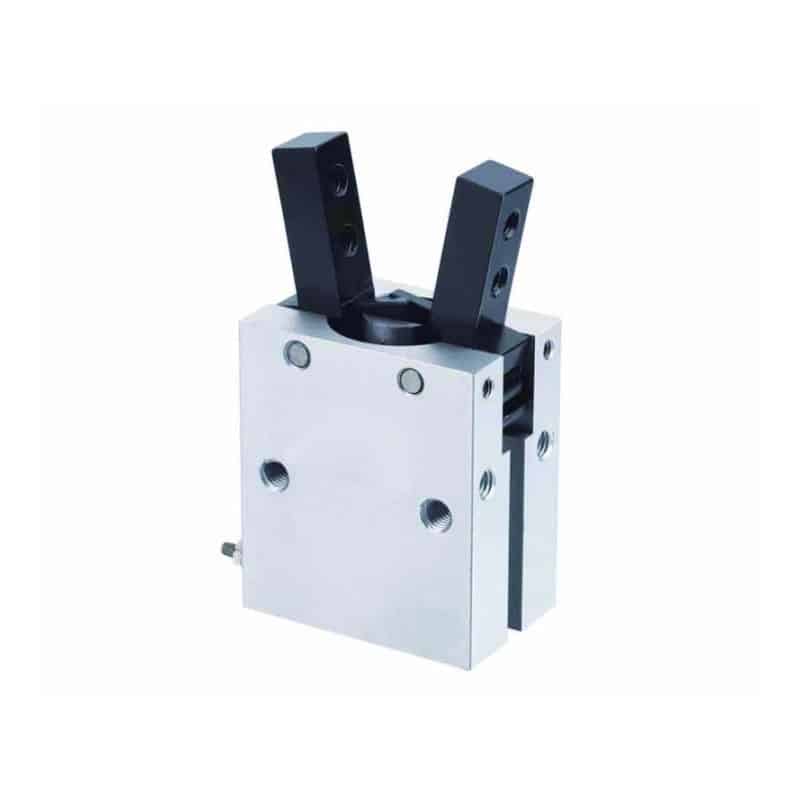
XHC parallel pneumatic gripper
This section is intentionally not another gripper-type catalog. For parallel, angular, three-jaw, toggle, and wide-opening selection, use the existing pneumatic gripper types guide. For a station-level compact-cylinder example outside the robot wrist, see compact cylinders in PCB assembly.
How Should You Control Finger Length, Offset, and Jaw Moment?
SMC’s worked MHZ2 example reports 24 N at 0.4 MPa with a 30 mm gripping-point distance, and defines effective gripping force as the thrust of one finger (SMC MHZ catalog). The same body can have a different usable force and guide load when the fingers become longer.
Check four separate quantities:
- Per-finger gripping force: Read the catalog graph at the actual pressure and gripping-point distance.
- Finger guide moment: Apply the workpiece force at the real contact offset, including robot acceleration and impact.
- Contact pressure: Divide clamping force by pad contact area and compare it with the workpiece damage limit.
- Finger stiffness: Confirm deflection doesn’t move the part outside the process or sensor window.
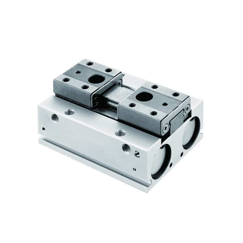
XHF low-profile parallel pneumatic gripper
What if the catalog force is adequate but the fingers exceed the permitted length or moment? Use shorter fingers, move the contact closer, add form-closed features, increase pad area, or select a gripper with a stronger guide. Raising pressure alone may increase part marking without fixing finger deflection.
Treat the contact point as a design variable. A compact body with long fingers can create a less compact load path than a slightly larger gripper whose jaws reach the part without an adapter. Compare the flange-to-contact distance, not only the body dimensions.
Mounting, Routing, and Service Envelope
ISO 9409-1 was confirmed in 2023 and uses only 6 pages to define the circular mechanical interface, while stating that the standard does not correlate interface size with load capacity (ISO 9409-1). The mounting plate must therefore satisfy the robot manual, tool load, fastener, stiffness, and locating requirements separately.
Model the full envelope in both jaw positions and across the robot path. Include fittings, speed controllers, sensor connectors, tube bend radius, cable strain relief, fastener access, quick-change motion, and the space needed to remove the gripper without disassembling the wrist.
Route flexible services so they don’t become a hidden load. A tight tube loop can pull on a small gripper, while an oversized loop can snag a fixture or enter a camera field. Anchor the service bundle near the wrist, keep repeated bending in the intended flex zone, and verify it at every extreme robot pose.
Use dowels or locating features when repeatable tool orientation matters. Fasteners provide clamp load; they shouldn’t be asked to locate a precision EOAT through clearance holes alone. ISO 9409-1 establishes interface exchangeability, not the flatness, stiffness, or tolerance stack of a custom adapter.
How Do Valves, Tubing, and Sensors Affect Timing?
SMC lists 180 cycles per minute for MHZ2 bores from 6-25 mm and 60 cycles per minute for 32-40 mm models, but those are maximum catalog frequencies (SMC MHZ catalog). Actual EOAT timing also depends on valve flow, tube volume, pressure during motion, finger mass, sensors, and PLC sequence.
Put the valve near the wrist when shorter pneumatic volume materially improves response, but include valve mass, cable mass, heat, ingress protection, and service access in the payload budget. A remote valve island reduces wrist mass but adds tube volume. Neither arrangement wins automatically.
Measure these events separately:
- robot reaches the permitted grip pose
- valve output changes state
- gripper closes far enough to contact the part
- pressure or position confirms a valid grip
- robot motion permission is issued
- release completes before the robot leaves the place position
Do not use a fixed delay as the only grip confirmation when a dropped part creates a hazard or quality risk. Position switches can confirm jaw state, but they may not prove part retention. Pressure logic can detect some faults, yet it also needs defined thresholds, timing, and fault handling.
The related solenoid valve operation guide explains valve states, while the pneumatic pressure-drop guide covers losses between the plant header and the moving tool.
What Safe State and Acceptance Tests Should the EOAT Use?
ISO/TR 20218-1:2018 is a 25-page safety-design guide for robot end-effectors, while ISO 10218-2:2025 is a 223-page standard for industrial robot applications and cells (ISO/TR 20218-1; ISO 10218-2:2025). The EOAT safe state must come from risk assessment, not a universal “open” or “closed” rule.
Ask what happens when air pressure, electrical power, communication, a sensor, or a tube fails. Dropping a heavy or sharp part may be the dominant hazard. In another process, retaining a hot or contaminated part could be worse. Select spring assist, pilot-operated checks, mechanical retention, controlled release, or redundant sensing only after that failure analysis.
Before production release, run a first-article test that records:
- complete EOAT mass, combined center of gravity, and configured payload data
- wrist interface, fasteners, locating features, stiffness, and service access
- grip force assumptions, finger length, contact pressure, and guide-moment approval
- dynamic picks at representative low, normal, and credible high acceleration
- part-present, jaw-position, pressure, and robot-permission timing
- safe response to air loss, power loss, sensor faults, and emergency stop
- repeatability after tool changes and after the service bundle has flexed
For U.S. servicing and maintenance, OSHA 29 CFR 1910.147 applies where unexpected energization, startup, or stored-energy release could cause injury (OSHA 1910.147). Commissioning tests don’t replace the site’s energy-control procedure.
FAQs About Compact Cylinders in End-of-Arm Tooling
SMC lists MHZ2 operating-pressure ranges from 0.1 to 0.7 MPa for several double-acting 16-40 mm models and identifies gripping force per finger (SMC MHZ catalog). These FAQs address the system checks that remain after a compact actuator has been shortlisted.
Does a lighter EOAT always improve robot cycle time?
No. Lower mass can help, but center of gravity and inertia also control the available motion envelope. In the worked example, 2.30 kg at a combined 114 mm offset must still be checked against the selected robot’s load diagram. Finger reach and workpiece position can matter more than body mass.
How do I calculate the EOAT center of gravity?
Multiply each component mass by its distance from the flange, add those products, then divide by total mass. The example produces 0.2623 kg m divided by 2.30 kg, or about 114 mm. Use three-dimensional coordinates and the robot manufacturer’s inertia method for final controller data.
Does ISO 9409-1 prove that the EOAT can carry the load?
No. The 6-page ISO 9409-1 standard defines the circular plate interface, designation, marking, exchangeability, and orientation. It explicitly does not correlate the interface with load-carrying ranges. Payload, center of gravity, moments, inertia, fasteners, and adapter stiffness still require model-specific verification.
How much gripping force does a robot EOAT need?
It depends on mass, acceleration direction, friction, jaw count, contact geometry, finger offset, impact, and the selected design factor. SMC’s 0.1 kg example uses 20 times workpiece weight and obtains 19.6 N. Treat that as catalog guidance, then validate the actual part and robot path.
Should the gripper open or stay closed after air loss?
There is no universal answer. ISO/TR 20218-1 contains 25 pages of end-effector safety guidance, and ISO 10218-2:2025 covers robot-cell integration. Define the safer state from dropped-part, retained-part, pinch, thermal, contamination, recovery, and stored-energy hazards, then test the selected architecture.
Conclusion: Approve the Tool as a System
The worked EOAT totals 2.30 kg at a 114 mm combined offset, while its 1 kg workpiece needs an illustrative 49.5 N per jaw at 10 m/s2 under the stated friction and design-factor assumptions. Universal Robots and SMC both show why mass, center of gravity, pressure, contact point, and force must be approved together.
Freeze the tool as one configuration: robot model, flange, adapter, actuator, fingers, valve, sensors, fittings, service bundle, workpiece range, payload data, motion limits, grip logic, and failure response. A substitute compact cylinder or gripper is acceptable only when that complete evidence package still passes.
For a machine-specific review, send the robot model, load diagram, EOAT CAD, component masses, center-of-mass coordinates, part drawing, acceleration profile, pressure at the valve, finger geometry, sensor logic, and safe-state requirement through contact. Publisher background is available on About Bepto.
Sources and Retrieval Notes
-
ISO 9409-1:2004, retrieved 2026-07-10. Used for the 6-page circular mechanical-interface scope, 2023 confirmation, and explicit exclusion of load-carrying correlation.
-
ISO 9283:1998, retrieved 2026-07-10. Used for the 60-page robot performance-criteria and test-method scope and 2021 confirmation.
-
ISO/TR 20218-1:2018, retrieved 2026-07-10. Used for the 25-page end-effector safety-design and integration scope.
-
ISO 10218-2:2025, retrieved 2026-07-10. Used for the 223-page industrial robot application and robot-cell integration scope.
-
Universal Robots payload guidance, retrieved 2026-07-10. Used for combined tool-flange payload and center-of-gravity configuration.
-
Universal Robots maximum payload guidance, retrieved 2026-07-10. Used for the relationship among payload mass, center-of-gravity offset, inertia, acceleration, gripper, and workpiece.
-
SMC MHZ parallel air gripper catalog, retrieved 2026-07-10. Used for per-finger gripping force, pressure and gripping-point graphs, the 0.1 kg selection example, operating ranges, and maximum frequencies.
-
OSHA 29 CFR 1910.147, retrieved 2026-07-10. Used only for covered servicing and maintenance where unexpected startup or stored-energy release can cause injury.
-
Universal Robots Academy, Tool Configuration: TCP, orientation, payload & center of gravity, uploaded 2021-12-16. Embedded as a 4 minute 33 second setup overview; 31,341 views at verification.