

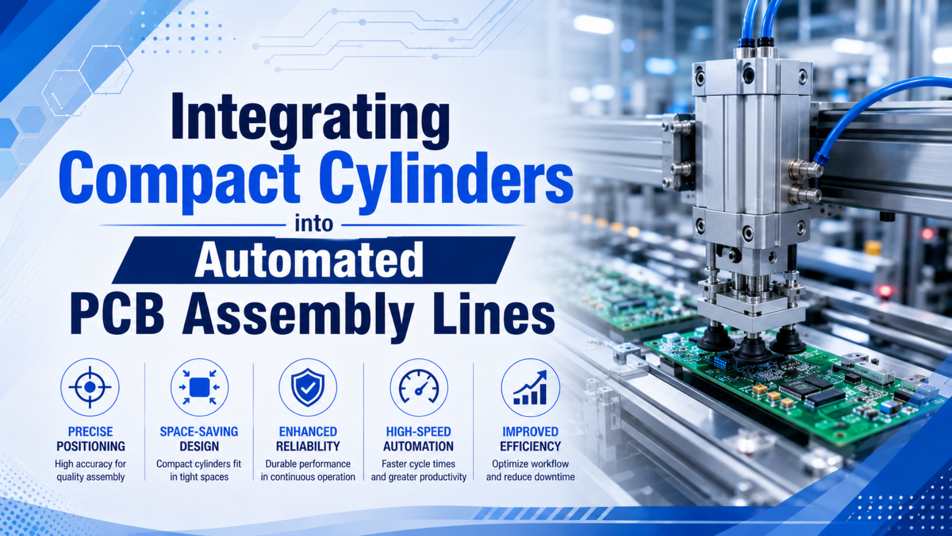
Integrating compact cylinders into automated PCB assembly lines works best when each actuator is tied to a station job: clamp, lift, locate, push, cover, reject, or fixture release. A compact pneumatic cylinder should not be specified as a vague “precision actuator.” It should be sized around force, stroke, takt time, air quality, sensor feedback, and keep-out zones around cameras, feeders, conveyors, and boards.
That distinction matters. IPC-A-610H is a 416-page electronics assembly acceptance standard, and IPC describes it as the most widely used acceptance standard in the electronics industry (IPC-A-610H, 2020). Your pneumatic design has to support inspection and repeatable handling. It cannot compensate for a weak fixture datum or an actuator that hits components instead of the carrier.
Key Takeaways
- Use compact cylinders for clear end-position tasks such as stops, clamps, lifts, diverters, and fixture locks.
- Keep high-precision placement claims separate from cylinder sizing. Electric or servo-pneumatic axes fit that problem better.
- ISO 8573-1 classifies compressed air by particles, water, and oil, so point-of-use air quality belongs in the RFQ.
- Size force and stroke before choosing sensors, valves, fittings, and mounting hardware.
Compact cylinder integration is the process of matching a short-stroke pneumatic actuator to one verified PCB station result: clamp, lift, stop, reject, locate, release, or cover. The proof is not a catalog phrase. The proof is measured force, stroke, timing, sensor state, and acceptance behavior at the machine.
In our experience, the cylinder is rarely the only cause of PCB line trouble. The real fault often sits one layer away: a board support that deflects, a flow control set too aggressively, a camera view blocked by a bracket, or a regulator that looks stable while the station is idle but drops during the move.
What Does Compact Cylinder Integration Mean in a PCB Assembly Line?
IPC says IPC-A-610H has 416 pages and is intended for inspectors, operators, and others interested in electronic assembly acceptance criteria (IPC-A-610H, 2020). In a PCB line, compact cylinder integration means making actuator motion support that acceptance process without adding board stress, contamination, blocked inspection, or unverified positioning claims.
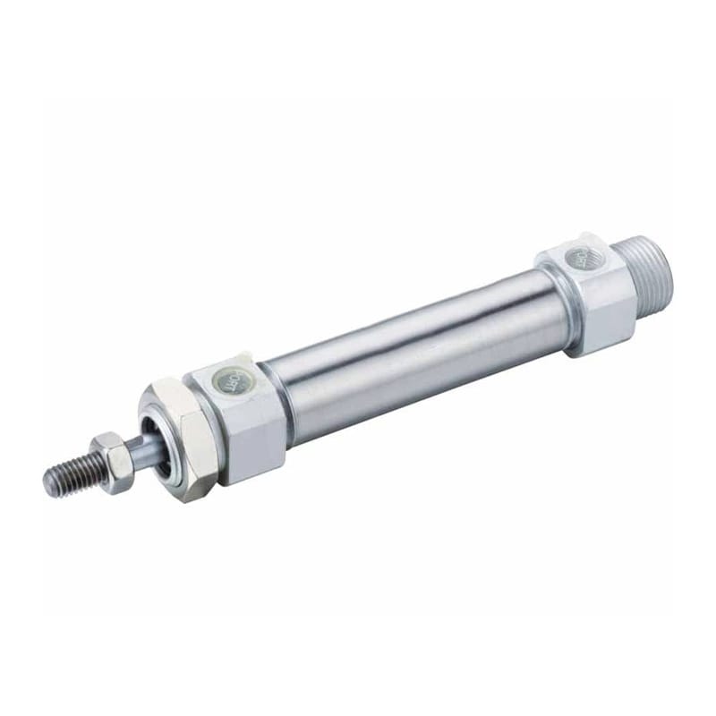
The useful starting point is the station job. A compact cylinder may raise a stop gate, lock a nest, eject a failed board, close a shield, trigger a paste fixture, or release a carrier. Those are different jobs. They need different bore sizes, stroke lengths, speed controls, switch logic, and maintenance access.
Don’t ask one small cylinder to solve every motion problem. It can be excellent at a short, repeatable two-position move. It is usually the wrong part when the board must stop at many recipe-dependent locations or follow a controlled path under a vision system.
Common PCB Station Jobs
| Station job | Cylinder task | Main risk to control |
|---|---|---|
| Conveyor stop | Raise or lower a board stop | Impact on board edge or pallet |
| Fixture clamp | Hold a PCB or carrier against a datum | Board flex, local component clearance |
| Lift table | Raise a nest into process position | Side load, guide stiffness, stroke timing |
| Reject lane | Push a failed board or carrier | Speed, alignment, soft contact |
| Cover or shield placement | Close a guard or process lid | Pinch point, repeatable end position |
| Tooling release | Unlock a fixture after inspection | Sensor confirmation before conveyor start |
The closer the cylinder is to the PCB, the more conservative the design should be. I would rather see a slower, guided, well-damped move than a fast actuator that wins 0.2 seconds and creates intermittent quality noise.
Where Do Compact Cylinders Fit, and Where Should They Not Be Used?
Festo’s actuator-selection guidance says pneumatics fit fast, repetitive motion with clear end positions, while electric actuators fit high positioning accuracy, flexible profiles, and synchronized motion (Festo, 2026). That is the boundary for PCB automation: use compact cylinders for defined mechanical actions, not open-ended placement accuracy.
For example, a compact cylinder is a strong fit for a board stop if the stop has a hard datum, sensor confirmation, and controlled approach speed. It is also a strong fit for a clamp that only needs to press a carrier against a reference face.
What about placing tiny components? That is usually not the compact cylinder’s job. Pick-and-place placement accuracy belongs to the motion platform, nozzle, vision correction, and machine calibration. A pneumatic cylinder may support that machine by actuating a guard, feeder lock, tray lift, or reject mechanism, but it should not be credited with the final placement tolerance.
If the question is truly about precision axis technology, route the reader to the cylinder versus electric actuator precision guide. If the question is closed-loop air positioning, use the servo pneumatic positioning article. This page should stay focused on integration decisions around compact cylinders.
How Should You Size Force, Bore, and Stroke for PCB Handling?
CAGI says most well-designed compressed-air systems have no more than 10% pressure drop between the compressor and point of use, and recommends checking pressure drop before raising compressor pressure (CAGI, 2022). For PCB compact cylinders, force sizing must use point-of-use pressure during motion, not only the regulator setting at idle.
Point-of-use pressure is the air pressure available at the station inlet, valve manifold, or actuator port while the cylinder is moving. It is the value that should drive force and speed calculations, because static regulator pressure can hide losses in tubing, fittings, filters, mufflers, and branch piping.
The basic force calculation is still simple:
Cylinder force = piston area x working pressure x efficiency allowanceThe engineering part is choosing the right load case. A clamp may only need a light hold-down force, but a push-off cylinder may see board edge friction, carrier drag, guide friction, and a safety factor. Too much force is not a virtue near thin boards. It can bend the panel, shift a fixture, or make a small misalignment look like a component problem.
For stroke, measure the real clearance stack: board thickness, carrier height, component keep-out, stopper height, mounting plate thickness, sensor bracket, fitting angle, and service access. A cylinder that fits in CAD can still fail when the speed controller points into a camera, feeder, or cable tray.
Use the smallest stroke that clears the process, but don’t run every compact cylinder at its mechanical limit. Leave room for mounting tolerance, switch adjustment, cushion behavior, and replacement parts. That extra few millimeters often saves the maintenance team later.
Force and Stroke Checklist
| Variable | What to capture in the RFQ | Why it matters |
|---|---|---|
| Working pressure | Dynamic point-of-use pressure | Prevents inflated force estimates |
| Required force | Load, friction, orientation, safety factor | Avoids board damage and undersizing |
| Stroke | Required travel plus adjustment margin | Protects keep-out and service space |
| Moving mass | Bracket, tooling, board, carrier | Sets impact and cushion risk |
| Contact point | Board edge, carrier, fixture, lid | Controls force path and damage mode |
| Cycle time | Extend time, retract time, dwell | Drives valve, tube, and flow sizing |
When a PCB line has random jams, I ask for the station pressure trace before I ask for a larger cylinder. A larger bore can hide a pressure-drop problem for a week, then create a harder impact when the air system is cleaned up.
How Do Air Quality, Cleanroom, and Static Controls Change the Pneumatic Design?
ISO 8573-1:2010 specifies compressed-air purity classes for particles, water, and oil, and ISO 14644-1:2015 classifies cleanroom air cleanliness using airborne particle concentrations from 0.1 um to 5 um (ISO 8573-1, 2010; ISO 14644-1, 2015). PCB pneumatic design should therefore specify air quality at the machine, not only filter hardware in the compressor room.
Point-of-use air quality is the compressed-air condition measured where the PCB station actually consumes air. It should name particle, water, and oil expectations separately, because a good compressor-room result does not prove that a downstream branch line, tube, or local filter is still clean.
Electronics assembly is sensitive to contamination in different ways. Oil carryover can collect dust. Water can corrode fittings and change valve response. Particles can end up on boards, fixtures, guide rails, or sensors. The right answer is not “add one filter.” It is a point-of-use air-quality target, a treatment train, and a maintenance interval.
The related ISO air quality standards guide explains the class notation in more detail. The coalescing filter article is the better internal link when the problem is oil aerosol or water mist.
Static control is a separate design layer. Pneumatic cylinders don’t create an ESD program by themselves, but the hardware around them can undermine one. Use conductive or grounded fixtures where the process requires it, route sensor cables away from high-current conductors, and document how the actuator bracket bonds into the machine frame.
Contamination Controls to Specify
| Risk | Pneumatic design response | Maintenance check |
|---|---|---|
| Particles | Point-of-use filtration and clean mounting | Inspect bowl, element, and downstream hose |
| Water | Dryer strategy and dew-point review | Drain receivers and check condensate |
| Oil aerosol | Coalescing filtration where needed | Track pressure drop across elements |
| Board contact residue | Avoid lubricant migration near work area | Use process-approved grease or dry design |
| Sensor instability | Shielded cable and clean grounding | Check cable clamps and connector strain |
How Should Compact Cylinders Be Mounted Around Conveyors, Cameras, and Feeders?
The Hermes Standard is published as IPC-HERMES-9852 and uses TCP/IP and XML for PCB-related data exchange between machines in SMT assembly lines (The Hermes Standard, 2026). That kind of line-level communication only helps if the physical station hardware keeps board flow, camera access, and sensor confirmation predictable.
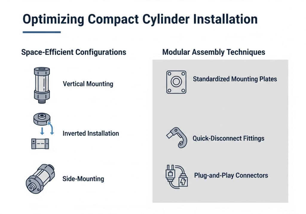
Mounting is where many compact-cylinder projects lose the benefit of a small actuator. A short body helps, but fittings, switches, speed controllers, cables, and manual access can take more space than the cylinder itself. Model the full pneumatic package, not just the actuator body.
Use guided hardware when the load is offset or the tooling needs to stay square. A compact cylinder rod is not a linear guide. If the cylinder pushes a fixture plate, support the plate with guides and let the cylinder supply force. That arrangement usually runs longer and gives the PLC cleaner end-position signals.
Mounting Rules That Prevent Rework
- Keep camera fields of view clear before locking the cylinder location.
- Put speed controllers and fittings where a technician can reach them.
- Avoid side load on the rod; use a guide or floating joint when needed.
- Separate pneumatic tubing from high-current motor and heater wiring.
- Add external stops when the process datum must not depend on the end cap.
- Confirm both cylinder positions before releasing the conveyor.
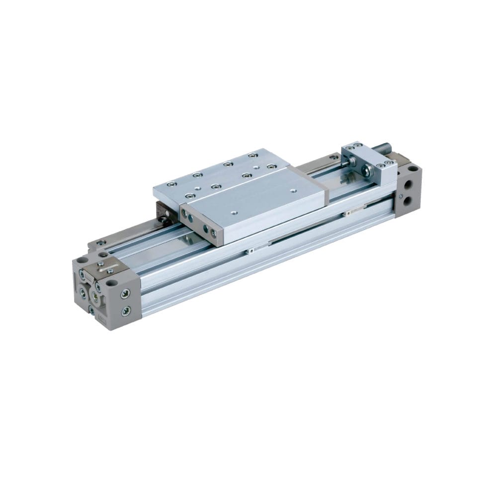
What if the line is already crowded? Then a guided compact cylinder, a rodless carriage, or a remote valve manifold may solve different parts of the space problem. The article on rodless pneumatic cylinder types is the right next step when stroke length, carriage guidance, or profile shape drives the decision.
When Should Rodless or Servo-Pneumatic Designs Replace a Compact Cylinder?
Festo describes an MPYE proportional directional valve as a 5/3-way valve that converts an analog input signal into a valve opening and can create a precise pneumatic positioning system with an external controller and displacement encoder (Festo Proportional Valves, 2026). If a PCB station needs controlled mid-stroke positioning, a simple compact cylinder with two switches is the wrong control architecture.
Servo-pneumatic positioning is closed-loop pneumatic motion using a variable valve command, feedback sensor, and controller correction. It can help when a PCB station needs moderate controlled stops, but it should be specified as a system rather than as a single upgraded cylinder.
A rodless or guided axis may be better when the actuator must move tooling along a conveyor edge, clear a wide board, or avoid a long rod projecting into the machine. A servo-pneumatic system may be better when the axis needs variable stop points, controlled deceleration, or position feedback through the stroke.
However, this upgrade should be deliberate. Servo pneumatics add valves, sensors, controller tuning, acceptance tests, and maintenance skills. Use them when the process result needs them, not because a catalog phrase sounds more precise.
What Maintenance Checks Prevent Quality Drift?
CAGI recommends changing filter elements when differential pressure exceeds 5-7 psig or at least every six months, and also recommends taps for pressure monitoring in distribution piping (CAGI, 2022). For PCB assembly, those checks protect timing, force, sensor response, and cleanliness before defects appear at inspection.
Maintenance should be station-specific. A board stop that runs every panel needs a different review than a shield cylinder that moves only during changeover. Keep a small record for each critical cylinder: pressure during motion, extend and retract time, switch response, fitting condition, guide play, and visible residue.
Also inspect the non-cylinder items. Mufflers clog. Speed controllers move. Tubing gets pinched behind a guard. A bracket loosens after many impacts. Those small changes can shift cycle time enough to break conveyor handoff logic or vision-trigger timing.
Practical Maintenance Table
| Interval | Check | Failure caught early |
|---|---|---|
| Shift start | Confirm extend/retract sensors and abnormal noise | Broken switch, loose mount, binding |
| Weekly | Check point-of-use pressure during the move | Low dynamic pressure, clogged path |
| Monthly | Inspect tubing, fittings, speed controls, and mufflers | Air leak, drifted speed, exhaust restriction |
| Six months or 5-7 psig filter drop | Replace or service filter element | Particle, water, or oil carryover |
| After product change | Recheck keep-out, contact point, and camera clearance | New board hitting old hardware |
The most useful maintenance number is often not total cycle count. It is the change in extend time under the same load and pressure. A cylinder that used to extend in 180 ms and now needs 260 ms is telling you something before the line stops.
RFQ Checklist for Compact Cylinders in PCB Assembly
ISO 8573-1 is a 9-page compressed-air purity standard, while ISO 14644-1 is a 37-page cleanroom classification standard focused on airborne particle concentration (ISO 8573-1, 2010; ISO 14644-1, 2015). A useful PCB compact-cylinder RFQ should combine actuator data with environment and acceptance data, not just bore and stroke.
Send the station drawing, not only a photo. Include the board or carrier size, the contact surface, the allowed force, the available mounting envelope, nearby cameras, feeder keep-out, tube routing, sensor type, voltage, PLC input type, and required cycle time.
For a replacement, include the current model number, photos from three sides, fitting orientation, switch part numbers, failure symptoms, and whether the problem is force, timing, leakage, contamination, or clearance. That lets the supplier choose between a compact cylinder, guided cylinder, rodless unit, gripper, or a control change.
RFQ Data to Send
| RFQ field | Good detail | Bad detail |
|---|---|---|
| Station function | “Raise PCB stop before AOI conveyor handoff” | “Need small cylinder” |
| Stroke and clearance | Travel, keep-out, fitting direction, service access | “About 30 mm” |
| Force requirement | Load, friction, board contact limit, safety factor | “Strong enough” |
| Speed target | Extend/retract time and dwell | “Fast” |
| Air quality | ISO 8573-1 class target or plant standard | “Clean air” |
| Sensors | Switch type, voltage, cable route, PLC input | “With sensor” |
| Environment | Cleanroom, solvent, ESD, temperature, residue risk | “Electronics line” |
FAQs About Compact Cylinders in PCB Assembly
IPC-A-610H was published on 2020-09-01 with 416 pages, and ISO 8573-1 remains the compressed-air purity-class reference for particles, water, and oil (IPC-A-610H, 2020; ISO 8573-1, 2010). These FAQ answers keep compact-cylinder claims tied to acceptance, air quality, and station design.
Can compact cylinders place PCB components accurately?
Usually, no. Compact cylinders can actuate stops, clamps, lifts, feeders, covers, and reject mechanisms, but component placement accuracy belongs to the placement machine, vision correction, nozzle, and motion axis. Festo’s guidance separates simple pneumatic end-position work from electric axes that need high positioning accuracy and flexible profiles.
What air quality should I specify for PCB pneumatic stations?
Use a written ISO 8573-1 target for particles, water, and oil at the point of use. The exact class depends on process risk, board exposure, lubricant restrictions, and plant standards. Don’t specify only a filter model, because downstream hoses, wet branches, and old pipe can change the air reaching the cylinder.
Do compact cylinders need position feedback?
Most compact-cylinder PCB stations need at least extend and retract confirmation. Continuous feedback is needed only when the process requires controlled mid-stroke positions or profile control. Enfield’s S2 example combines a proportional valve, sensors, and embedded electronics, which is a different system than a basic two-switch compact cylinder.
How do I avoid board damage from pneumatic clamps?
Limit force, support the board near the load path, clamp against a fixture datum rather than unsupported laminate, and control speed near contact. Size from point-of-use pressure and a realistic friction load. Then verify the result on the actual board, carrier, and product changeover condition.
When should I choose a rodless cylinder instead?
Choose a rodless or guided axis when the station needs a longer travel path, a moving carriage, or better support for offset tooling. A compact cylinder is short, but a rod and bracket can still consume space. For long conveyor-edge moves, compare guided rodless designs before forcing a standard compact cylinder into the envelope.
Conclusion
Compact cylinders can make automated PCB assembly lines cleaner, denser, and easier to maintain, but only when they are treated as station actuators with defined work. Freeze the task first. Then size force, stroke, speed, air quality, mounting, sensor logic, and maintenance checks around that task.
The weak version of this article would promise unsupported sub-millimeter accuracy. The practical version is simpler: use compact cylinders for reliable two-position actions, use guides when the load needs support, use servo-pneumatic or electric axes when the process requires controlled positions, and make every claim testable at the machine.
Source notes:
- IPC-A-610H product details, page count, publication date, and acceptance-standard context, retrieved 2026-07-08.
- ISO 8573-1:2010, compressed-air purity classes for particles, water, and oil, retrieved 2026-07-08.
- ISO 14644-1:2015, cleanroom classification by airborne particle concentration from 0.1 um to 5 um, retrieved 2026-07-08.
- CAGI Pressure Drop Technical Brief, 10% pressure-drop guideline and 5-7 psig filter differential guidance, retrieved 2026-07-08.
- Festo actuator-selection article, pneumatic and electric actuator fit, retrieved 2026-07-08.
- Festo proportional valves, MPYE positioning-system description, retrieved 2026-07-08.
- Enfield S2 cylinder positioning system, proportional valve, sensors, embedded electronics, and mid-stroke positioning description, retrieved 2026-07-08.
- The Hermes Standard, IPC-HERMES-9852, TCP/IP and XML board-data exchange context, retrieved 2026-07-08.