

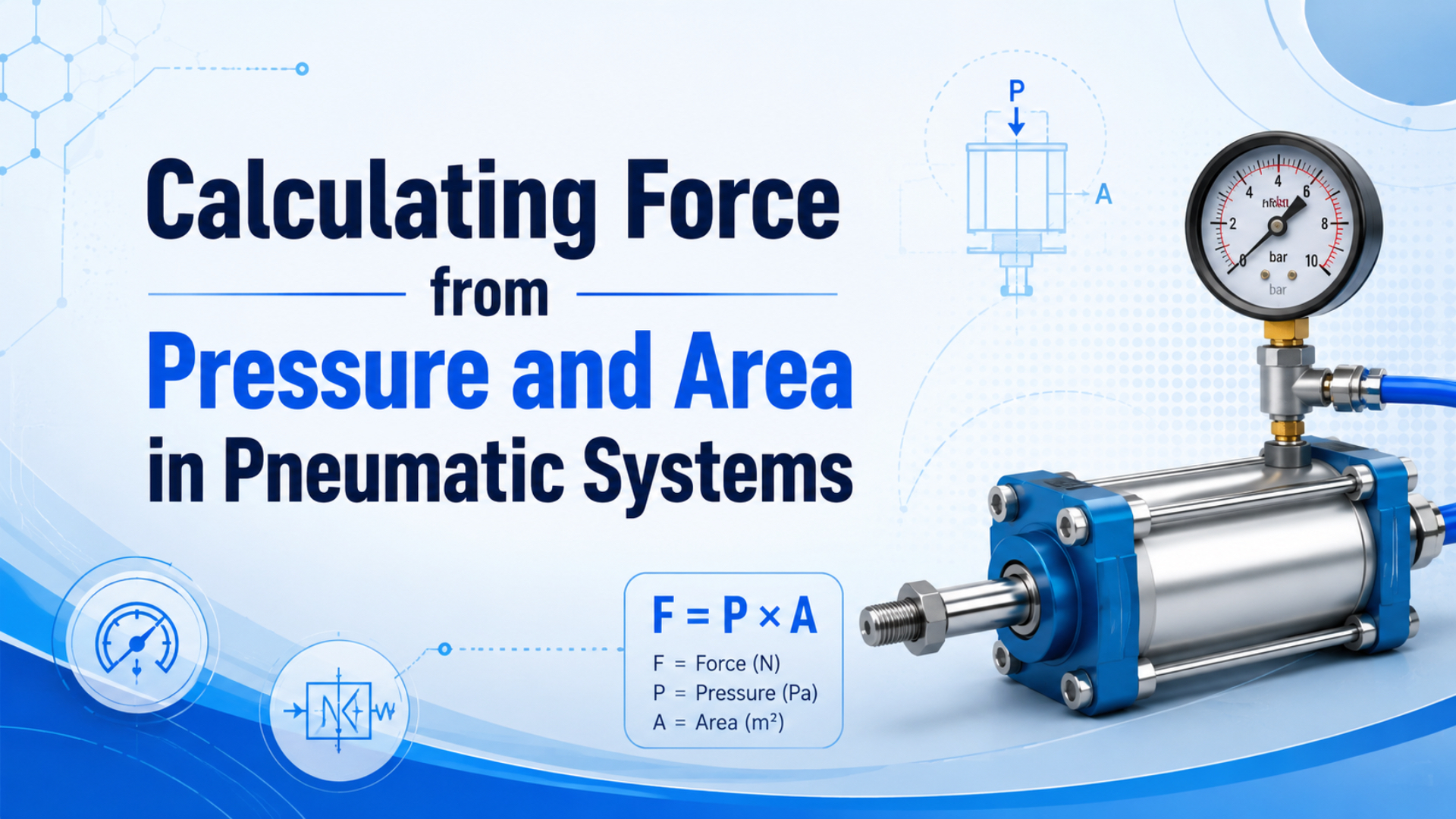
Pneumatic force starts with a simple rule: force equals working pressure times effective area. AutomationDirect’s cylinder sizing page shows the same relationship and gives a practical checkpoint: a 4 inch bore has 12.57 in2 piston area, so 100 psi produces 1,257 lbf before rod area and losses (AutomationDirect, 2026).
That formula is useful, but it is not the whole selection. Use the pressure at the actuator port during motion, not only the compressor-room gauge. Use piston area for extension. Use piston area minus rod area for single-rod retraction. Then add margin for friction, pressure drop, back pressure, acceleration, and load direction.
This article is narrower than our guide to Pascal’s Law in pneumatic systems and more focused than the broader cylinder formula guide. The job here is one worksheet: pressure, area, force, and bore size.
Key Takeaways
- Basic cylinder force is
F = P x A; AutomationDirect’s 4 inch, 100 psi example gives 1,257 lbf before practical losses.- Retraction force on a single-rod cylinder is lower because the rod removes effective piston area.
- CAGI says well-designed compressed-air systems usually stay within 10% pressure drop from compressor to point of use.
- Size the bore from measured working pressure, required load, stroke direction, friction, and safety margin.
Quick Answer: Force Equals Pressure x Effective Area
The quick calculation is F = P x A. AutomationDirect states that cylinder force is effective piston surface area multiplied by differential pressure, and its 4 inch bore example gives 1,257 lbf at 100 psi (AutomationDirect, 2026).
Use this first-pass formula:
Force = pressure x effective area
F = P x A
For imperial calculations:
pressure in psi x area in in2 = force in lbfFor metric pneumatic calculations:
1 bar = 0.1 N/mm2
force in N = pressure in bar x 0.1 x area in mm2
That metric line prevents a common 10x error. A 50 mm bore has 1,963 mm2 piston area. At 6 bar, pressure is 0.6 N/mm2, so the theoretical extension force is about 1,178 N before losses. It is not 11,778 N.
Pneumatic cylinder force is the linear push or pull created when compressed air pressure acts on effective piston area. For example, AutomationDirect’s 4 inch bore data gives 12.57 in2 area, so 100 psi produces 1,257 lbf before practical losses. Therefore, the first calculation should state three values together: working pressure, effective area, and stroke direction (AutomationDirect, 2026). If any one is missing, the force number is not ready for selection. Specifically, record whether the number describes extension, retraction, spring return, or rodless carriage force, because each case can use a different effective area and a different loss allowance. That discipline also keeps sales, maintenance, and design teams from comparing different force ratings as if they were the same value. It also makes later troubleshooting faster.
The formula is a checkpoint, not a guarantee. A clean force number only tells you what the actuator could do if the pressure reaches the correct chamber, the area is correct, and the load path does not waste the force before it reaches the work.
Which Pressure Value Should You Use?
Use differential pressure across the actuator chamber, measured as close as practical to the cylinder during motion. CAGI says most well-designed air systems have no more than 10% pressure drop between compressor discharge and point of use (CAGI, 2026).
That means the compressor discharge gauge is usually too generous for force sizing. A system showing 100 psig at the compressor may deliver less at the valve manifold and less again at the actuator port during a fast stroke. The piston only reacts to the pressure that reaches the chamber.
Use these pressure terms carefully:
| Pressure value | Where it is measured | Use for force sizing? |
|---|---|---|
| Compressor discharge pressure | Compressor outlet | No, too far upstream |
| Header pressure | Main plant-air line | Useful for diagnosis, not final force |
| Regulator outlet pressure | FRL or machine regulator | Good static check, still verify during motion |
| Actuator port pressure | Near cylinder port while moving | Best working value for force |
| Back pressure | Opposite chamber or exhaust side | Subtract it from driving pressure |
For basic cylinder force in a vented pneumatic circuit, use gauge pressure or differential pressure. Do not add atmospheric pressure to a simple push-force calculation. Absolute pressure belongs in gas-compression, storage, and air-consumption work, which the broader basic pneumatic law article covers.
Differential pressure is the pressure difference that acts across the piston, not the best pressure reading anywhere in the plant. CAGI says a well-designed compressed-air system usually stays within 10% pressure drop between compressor and point of use; in other words, force calculations should use local measured pressure, then subtract exhaust-side back pressure when it is not negligible (CAGI, 2026). That single check often explains weak strokes without changing bore. For instance, a cylinder fed from an 80 psi regulator but exhausting through a restricted muffler may behave like a smaller actuator because the opposing chamber is still carrying pressure during movement. As a result, pressure testing should happen during the failed cycle, not after the machine has stopped. This avoids blaming the wrong component.
In our experience, weak-cylinder complaints become easier once the team records pressure during the exact failed movement. A static gauge can look fine before the cycle starts. The real question is what the actuator sees while the valve, tube, fittings, and muffler are flowing.
Net force = (driving pressure - back pressure) x effective areaIf the drive side is 80 psi, the exhaust side is carrying 8 psi of back pressure, and the piston area is 3.14 in2, net theoretical force is:
(80 - 8) x 3.14 = 226 lbf before friction and load dynamicsFor field diagnosis, pair this article with pressure fluctuation troubleshooting and the guide to air cylinder working pressure.
How Do You Calculate Effective Area?
Effective area is the piston area that pressure actually acts on. ISO 15552 covers detachable-mounting pneumatic cylinders rated to 1,000 kPa, or 10 bar, with bores from 32 mm to 320 mm, confirmed current in 2025 (ISO, 2025).
For extension on a single-rod cylinder, pressure acts on the full piston area:
piston area = pi x bore^2 / 4
extension force = pressure x piston area
For retraction, the rod occupies part of the piston face:
rod area = pi x rod diameter^2 / 4
retract effective area = piston area - rod area
retraction force = pressure x retract effective area
AutomationDirect gives a clear imperial example: a 4 inch bore has 12.57 in2 area and gives 1,257 lbf at 100 psi; with a 1 inch rod on retraction, effective area drops to 11.78 in2 and force drops to 1,178 lbf at the same pressure (AutomationDirect, 2026).
Effective piston area is the area exposed to useful pressure after the geometry of the cylinder is considered. Specifically, extension on a single-rod cylinder uses full piston area, while retraction uses piston area minus rod area. ISO 15552’s standard-cylinder scope reaches 10 bar and bores from 32 mm to 320 mm, so a worksheet should confirm both the formula area and the catalog bore before quoting force (ISO, 2025). In particular, do not use outside barrel diameter, outside surface area, or nominal product family size as a substitute for the bore and rod dimensions that define force. This is also why replacement reviews should ask for rod diameter, not only stroke and mounting style. The missing rod value changes pull force.
| Calculation | Formula | 4 inch bore, 1 inch rod |
|---|---|---|
| Piston area | pi x bore^2 / 4 |
12.57 in2 |
| Rod area | pi x rod^2 / 4 |
0.79 in2 |
| Retract area | piston area - rod area |
11.78 in2 |
| Extend force at 100 psi | 100 x 12.57 |
1,257 lbf |
| Retract force at 100 psi | 100 x 11.78 |
1,178 lbf |
Do not confuse piston area with outside cylinder surface area. Outside surface area helps with coating, cleaning, heat exposure, or corrosion review. It does not calculate push force. Use the separate guide to surface area for pneumatic cylinders when the question is finish, exposure, or heat.
If the article you need is rod-side detail, use the dedicated guide to pneumatic cylinder rod area. If the actuator is rodless, check the product family. A magnetic rodless cylinder, band-style cylinder, or guided slide can have coupling and guide limits that matter before the theoretical piston force is reached.
What Reduces Usable Force?
Theoretical force becomes usable force only after losses are handled. AutomationDirect notes that pressure in force equations represents differential pressure and that systems should be designed with calculated forces at least 25% above actual requirements (AutomationDirect, 2026).
The most common losses are ordinary machine details:
| Loss source | What it does | Field check |
|---|---|---|
| Seal and guide friction | Uses part of the cylinder thrust | Compare breakaway and moving force |
| Pressure drop | Lowers chamber pressure during flow | Gauge near the actuator during stroke |
| Back pressure | Opposes the driving chamber | Check exhaust restriction and muffler |
| Side load | Turns thrust into guide friction | Check alignment and external support |
| Acceleration force | Consumes force to move mass faster | Calculate mass x acceleration |
| Vertical load | Adds gravity to the force demand | Include load direction and holding risk |
CAGI lists causes of pressure drop that fit many weak-cylinder cases: piping, fittings, filters, dryers, corrosion, leaks, receiver condition, and excessive air velocity. It also recommends air velocity through piping at 20 ft/s or lower to reduce turbulence and pressure drop (CAGI, 2026).
Use a staged formula when the application is near the limit:
theoretical force = working pressure x effective area
net force = (drive pressure - back pressure) x effective area
effective force = net force x (1 - friction allowance)
safe load = effective force / safety factor
The mistake is not using a safety factor. The mistake is using one safety factor to hide several unknowns. Pressure stability, friction, back pressure, acceleration, mounting alignment, and load variation each deserve a quick check before the bore is increased.
How Do You Size Bore From Required Load?
Work backward from the required load. AutomationDirect recommends factoring in 25% more force than the load actually requires to overcome friction, pressure drop, and other factors, then choosing the next larger available cylinder bore (AutomationDirect, 2026).
The basic bore-sizing workflow is:
- Define the load force, stroke direction, speed, and orientation.
- Choose the lowest reliable working pressure at the actuator port.
- Add force for friction, acceleration, process load, and gravity.
- Apply the safety factor or design margin.
- Divide required force by working pressure to get required area.
- Convert required area to bore.
- Select the next standard bore and verify mounting, flow, cushioning, and air use.
Use this formula for the first pass:
required theoretical force = actual load force x margin
required area = required theoretical force / working pressure
bore = sqrt(4 x required area / pi)
Example:
actual load force = 400 lbf
margin = 1.25
required theoretical force = 500 lbf
working pressure = 80 psi
required area = 500 / 80 = 6.25 in2
bore = sqrt(4 x 6.25 / pi) = 2.82 in
Choose the next larger standard bore, then check the real catalog. If 3 inch is the next common bore, the theoretical extension force at 80 psi is:
3 inch bore area = 7.07 in2
force = 80 x 7.07 = 566 lbf before lossesFor standard product selection, connect force sizing to the physical part family. A standard pneumatic cylinder also needs the right solenoid valve, tube route, fitting size, and FRL unit. A bore-only selection can still fail if the air path cannot feed it.
Worked Examples and RFQ Checks
Unit checks matter because NIST lists 1 psi as 6,894.757 pascals, while pneumatic catalogs may mix psi, bar, MPa, in2, and mm2 (NIST, 2025). Write the unit after every number before trusting the result.
Example 1: Metric Extension Force
bore = 63 mm
pressure = 6 bar
area = pi x 63^2 / 4 = 3,117 mm2
6 bar = 0.6 N/mm2
theoretical extension force = 0.6 x 3,117 = 1,870 N
Use that number as the top of the worksheet. If the application needs a 1,200 N safe load and you use a 1.5 safety factor after losses, the 63 mm bore may be tight once friction, pressure drop, and acceleration are added. Check before ordering.
Example 2: Imperial Retraction Force
bore = 2.5 in
rod = 0.625 in
pressure = 90 psi
piston area = pi x 2.5^2 / 4 = 4.91 in2
rod area = pi x 0.625^2 / 4 = 0.31 in2
retract area = 4.91 - 0.31 = 4.60 in2
theoretical retract force = 90 x 4.60 = 414 lbf
If the load needs 400 lbf pulling force, this looks close but risky. Add friction and pressure variation, and the safe load will probably fall below the target. Either raise local working pressure within component limits, reduce losses, or select a larger bore.
Example 3: Back-Pressure Check
bore = 2 in
area = 3.14 in2
drive pressure = 80 psi
back pressure = 8 psi
net pressure = 72 psi
net theoretical force = 72 x 3.14 = 226 lbf
That is why exhaust restrictions matter. A clogged muffler, long tube, small fitting, or aggressive meter-out setting can turn a correct force calculation into a weak stroke.
RFQ Data to Send
Send these values when you ask for a cylinder sizing review:
| Data | Why it matters |
|---|---|
| Required push and pull force | Sets bore and rod-side area check |
| Working pressure during motion | Avoids compressor-gauge sizing errors |
| Bore, rod, and stroke if replacing | Confirms area and dimensional fit |
| Load mass and orientation | Adds gravity and acceleration checks |
| Target speed or cycle time | Connects force sizing to valve and flow |
| Valve, tube length, and fitting sizes | Finds pressure drop and back-pressure risks |
| Mounting style and side load | Protects guide life and alignment |
| Environment and duty cycle | Sets seal, lubrication, and margin needs |
The better worksheet is not longer. It is more specific. If you can name pressure, area, load, movement direction, and losses, the bore choice usually becomes clear.
FAQs About Force Calculations in Pneumatic Systems
AutomationDirect’s cylinder sizing reference ties together force, pressure, bore area, rod-side retraction, and the 25% design-margin starting point, which makes it a practical source for common force-calculation questions (AutomationDirect, 2026).
What is the basic formula for pneumatic cylinder force?
The basic formula is F = P x A, where force equals working pressure times effective area. Use psi with in2 for lbf, or convert bar to N/mm2 for metric work. For a simple metric shortcut, 1 bar = 0.1 N/mm2, so 6 bar equals 0.6 N/mm2.
Should I use gauge pressure or absolute pressure?
Use gauge pressure or differential pressure for a basic cylinder force calculation in a vented pneumatic circuit. The piston responds to pressure difference across the chamber. Use absolute pressure when you calculate gas compression, air storage, receiver sizing, or air consumption, where atmospheric pressure is part of the gas state.
Why is retraction force lower than extension force?
Retraction force is lower on a single-rod cylinder because the rod removes part of the pressure-acting area. AutomationDirect’s 4 inch bore example drops from 12.57 in2 full piston area to 11.78 in2 effective retract area with a 1 inch rod, reducing 100 psi force from 1,257 lbf to 1,178 lbf.
How much safety margin should I use?
AutomationDirect recommends calculated force at least 25% above the actual requirement. Treat that as a starting point. Use more margin for vertical loads, shock, variable friction, poor air stability, high duty cycle, dirty environments, side load, worn cylinders, or safety-related holding tasks.
What if the calculated force still does not move the load?
Measure pressure at the actuator port during the failed stroke, check back pressure on the exhaust side, and inspect guide alignment, side load, seals, mufflers, fittings, tubing, and valve flow. The formula may be correct while the machine loses usable pressure or wastes force through friction.
Final Check Before Selection
ISO 15552 defines the 10 bar standard-cylinder scope, CAGI gives the 10% pressure-drop reference for well-designed systems, and AutomationDirect recommends at least 25% calculated force margin above the actual requirement (ISO, 2025; CAGI, 2026; AutomationDirect, 2026).
Use F = P x A to make the first calculation. Then make it usable: select the right pressure value, calculate the correct effective area, subtract back pressure, allow for friction, add margin, and choose the next standard bore that still fits the machine.
The practical rule is short: pressure creates force, area scales it, and the air circuit decides how much of that force reaches the load.
Sources
- AutomationDirect: Cylinder Sizing and Force, force formula, bore-area table, 4 inch bore at 100 psi, rod-side force example, differential-pressure note, and 25% margin guidance. Retrieved 2026-07-08.
- AutomationDirect video: How to Select a Pneumatic Cylinder, force-based bore selection and 25% allowance before selecting the next available cylinder size. Retrieved 2026-07-08.
- CAGI: Technical Brief on Pressure Drop, 10% pressure-drop reference, pressure-drop causes, 20 ft/s velocity guidance, and pressure-drop mitigation checklist. Retrieved 2026-07-08.
- ISO 15552:2018, 1,000 kPa (10 bar) detachable-mounting pneumatic-cylinder scope, 32 mm to 320 mm bore range, and 2025 confirmation. Retrieved 2026-07-08.
- NIST: Pressure and Gas Flow Unit Conversions, pressure-unit conversion reference including psi and pascal values. Retrieved 2026-07-08.