

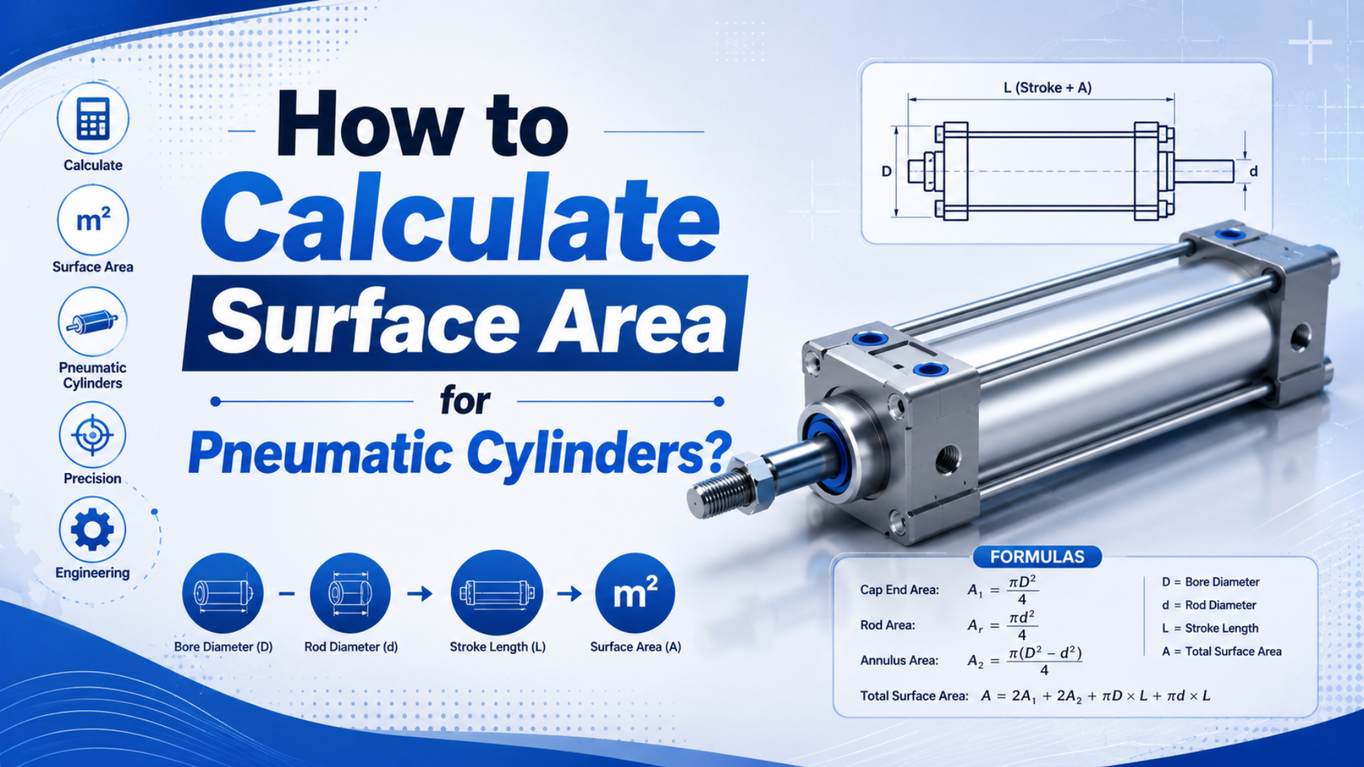
Pneumatic cylinder surface area is calculated differently depending on which surface you mean. The cylinder barrel uses curved-wall area, the piston face uses circular area, the exposed rod uses rod circumference times length, and coating or heat checks need the exposed external surfaces, not the pressure-force area.
That distinction prevents a common mistake. A piston area calculation helps estimate force. A barrel surface-area calculation helps estimate coating, cleaning, inspection, and heat exchange. A rod surface-area calculation helps estimate exposed chrome, wiper contact, corrosion exposure, and protective boot coverage.
Key Takeaways
- Barrel or rod outside area:
A = pi x D x L.- Piston force area:
A = pi x D^2 / 4.- ISO 15552 covers 32-320 mm, 10 bar cylinders; measured dimensions still decide area (ISO 15552, 2018).
The practical rule is simple: name the surface before using a formula. “Cylinder area” can mean barrel coating area, piston pressure area, rod exposed area, seal contact area, or heat-transfer area. Those are not interchangeable.
What is the Basic Cylinder Surface Area Formula?
Use A = pi x D x L for curved cylinder wall area, and use A = 2 x pi x r^2 + 2 x pi x r x L only when both flat ends count. ISO 15552 covers 10 bar pneumatic cylinders with 32-320 mm bores (ISO 15552, 2018).
For a pneumatic cylinder body, the first decision is whether you need the curved barrel area only or a rough external envelope. The curved barrel area is usually enough for tube coating, cleaning, basic heat exposure, or inspection planning.
Use the diameter form when you know outside diameter:
Curved barrel area = pi x outside diameter x barrel lengthUse the radius form when the drawing gives radius:
Curved barrel area = 2 x pi x radius x barrel lengthFor a simplified closed cylinder with two flat ends:
Total simple-cylinder area = 2 x pi x radius^2 + 2 x pi x radius x lengthReal pneumatic cylinders are not perfect closed cans. Tie rods, end caps, ports, cushions, sensor slots, mounting lugs, and rod glands add or hide surface area. For quotes, use catalog dimensions or CAD. For a quick estimate, the formulas above are good starting points.
How Do You Calculate Piston Surface Area?
Piston face area is A = pi x D^2 / 4; it is the pressure area for force, not coating coverage. NIST lists 1 psi as 6,894.757 Pa, so convert pressure units before multiplying area and pressure (NIST, 2025).
Use piston area when you care about force:
Piston face area = pi x bore^2 / 4
Force = pressure x piston face area
Example for a 63 mm bore:
Area = pi x 63^2 / 4 = 3,117 mm2
At 6 bar = 600,000 Pa
Ideal extend force = 600,000 x 0.003117 = 1,870 N
That is not the barrel surface area. It is the pressure area on the piston face. If you use this number for paint or heat dissipation, the answer will be wrong.
For a broader geometry refresher before the pneumatic-force step, compare this with the separate guide on working out the total surface area of a cylinder.
| Bore | Piston face area | Ideal force at 6 bar |
|---|---|---|
| 32 mm | 804 mm2 | 482 N |
| 50 mm | 1,963 mm2 | 1,178 N |
| 63 mm | 3,117 mm2 | 1,870 N |
| 80 mm | 5,027 mm2 | 3,016 N |
| 100 mm | 7,854 mm2 | 4,712 N |
For double-acting cylinders, retract force is lower because the rod occupies part of the rod-side chamber. Subtract rod area before calculating retract force.
Piston Area vs Barrel Surface Area
Piston area grows with diameter squared, but curved barrel area grows linearly with diameter and length. ISO 15552’s 32-320 mm bore range makes this difference large: a 100 mm bore has about 9.77 times the piston area of a 32 mm bore, before stroke length is even considered (ISO 15552, 2018).
For the same stroke length, a larger bore gives more force much faster than it increases barrel wall area. That is why force sizing and coating-area estimating should stay separate.
Compare a 100 mm bore and 32 mm bore:
Piston area ratio = (100 / 32)^2 = 9.77
Curved-area ratio at same length = 100 / 32 = 3.13
This also matters for heat. A larger cylinder can generate or absorb more work, but its surface area does not increase as quickly as its piston area. In high-cycle service, that can make thermal review worth doing.
If the job is specifically a rodless cylinder tube or housing, keep the calculation narrower; rodless actuator profiles add guide, carriage, and slot surfaces that a simple round-cylinder sketch does not show.
From replacement RFQs, the fastest way to catch a bad calculation is to ask what the area is for. If the answer is “force,” use piston area. If the answer is “paint,” use exposed outside surface. If the answer is “rod wear,” use rod and seal contact.
What is Rod Surface Area Calculation?
Rod surface area is the exposed cylindrical area of the piston rod, usually calculated as A = pi x D x L. ASTM B177/B177M covers engineering chromium electroplating as a guide for smooth, adherent chromium coatings of desired thickness, so rod exposure matters for plating and repair planning (ASTM B177/B177M, 2021).
For a straight exposed rod:
Rod outside surface area = pi x rod diameter x exposed lengthExample:
Rod diameter = 20 mm
Exposed length = 300 mm
Rod surface area = pi x 20 x 300 = 18,850 mm2
Convert that to square meters:
18,850 mm2 = 0.01885 m2Use this number for exposed rod cleaning, visible coating or plating estimates, corrosion exposure, and boot coverage. Do not confuse it with rod cross-section area. Rod cross-section area is pi x D^2 / 4, and it is used when subtracting rod area from retract-side piston area.
| Rod calculation | Formula | Typical use |
|---|---|---|
| Exposed rod surface | pi x D x L |
plating, cleaning, boot coverage |
| Rod cross-section | pi x D^2 / 4 |
retract force, buckling inputs |
| Rod-end face | pi x D^2 / 4 |
exposed end face or contact face |
How Do Rod-Side Area and Seal Contact Change the Answer?
Rod-side force uses piston area minus rod cross-section, while seal contact uses circumference times contact width. NIST lists 1 psi as 6,894.757 Pa, so align pressure and area units before comparing extend force, retract force, and seal contact (NIST, 2025).
For retract force:
Rod-side effective area = piston area - rod cross-section area
Retract force = pressure x rod-side effective area
For seal contact estimates:
Seal contact band area = pi x contact diameter x contact widthThat seal band area is a maintenance and friction discussion, not the same as pressure area. A narrow seal can create a small contact band but still hold pressure. A worn or damaged rod surface can shorten seal life even if all force calculations look correct.
For round seal-band and bore-measurement checks on slotless actuators, the companion guide on rodless cylinder circumference keeps circumference separate from surface area.
For troubleshooting, separate the questions:
- Weak retract stroke: check rod-side effective pressure area, pressure drop, and load.
- Rod corrosion: check exposed rod surface area, environment, and protection.
- Seal wear: check rod surface finish, side load, lubrication, contamination, and seal contact path.
- Coating estimate: check exposed external surfaces, not internal pressure areas.
How Do You Calculate Heat Transfer Surface Area?
Heat-transfer area is the exposed surface that exchanges heat with air or another medium. NASA describes 3 heat-transfer modes: conduction, convection, and radiation, so cylinder area belongs in the heat path, not in the force formula (NASA Glenn, 2026).
For a practical pneumatic cylinder estimate, start with exposed outside surfaces:
Approximate heat-transfer area =
  exposed barrel curved area
  + exposed end-cap area
  + exposed rod area
  + added fin or bracket area when relevant
Then apply the appropriate thermal model. A simple convection expression is often written as:
Heat transfer rate = h x A x temperature differenceThe hard part is not the area formula. It is selecting the correct heat-transfer coefficient, airflow condition, cylinder material, duty cycle, and heat source. A high-speed pneumatic cylinder may heat from seal friction, compressed-air temperature, ambient enclosure temperature, or repeated cushioning work.
Festo notes that adjustable pneumatic cushioning depends on moving mass, speed at damping, target deceleration, working pressure, and cylinder resistance (Festo, 2022). Surface area is only one part of that thermal and motion picture.
What Surface Area Do Coating and Plating Quotes Need?
Coating and plating quotes need the exposed surface that will actually receive treatment, plus masking and waste allowances. ASTM B177/B177M covers engineering chromium electroplating procedures and test methods, so rod area and specified coating thickness must be quoted together (ASTM B177/B177M, 2021).
For a simple rod plating volume estimate:
Plating volume = exposed rod surface area x plating thicknessFor paint or coating:
Coating material needed =
  exposed surface area / coverage rate
  + waste allowance
Send the supplier:
- Part drawing or measured diameter and length.
- Which faces are masked.
- Whether threads, rod ends, wrench flats, or grooves are included.
- Required coating or plating standard.
- Required inspection method.
- Quantity and rework allowance.
Do not use the piston force area for a plating quote. Do not include hidden internal surfaces unless the process actually treats them. If only the rod is replated, the barrel surface area is irrelevant.
When the supplier asks whether you mean total surface area or curved surface area, the TSA vs CSA guide for rodless cylinder calculations gives the scope language to keep the quote clean.
What Should You Measure Before Calculating?
Measure outside diameter, bore, rod diameter, exposed length, stroke, and any surface features before calculating. AutomationDirect describes pneumatic cylinders as using compressed air acting on a piston inside a cylinder to move a load, which is why the piston, rod, and body surfaces serve different functions (AutomationDirect, 2024).
Use this checklist:
| Measurement | Use it for | Tool or source |
|---|---|---|
| Bore diameter | piston face area, force | catalog, drawing, bore gauge |
| Barrel outside diameter | coating, heat, cleaning | calipers, drawing, catalog |
| Barrel exposed length | coating, heat, inspection | drawing or tape measure |
| Rod diameter | rod surface and retract area | calipers, catalog |
| Exposed rod length | plating, corrosion, boot | stroke and installed position |
| End-cap dimensions | rough external area | CAD, drawing, supplier data |
| Mounting hardware | exposed coating area | drawing or physical inspection |
For replacement work, photographs help, but they are not dimensions. If the project is about coating, send the surfaces to be coated. If the project is about force, send bore, rod diameter, pressure, load, and stroke. If the project is about heat, send duty cycle, speed, pressure, ambient temperature, and enclosure condition.
For actuator-family matching beyond area math, start from the pneumatic cylinders category and then verify the specific bore, stroke, guide style, and mounting pattern.
Common Mistakes in Pneumatic Cylinder Surface Area
The biggest mistakes are mixing piston face area with barrel area, using nominal sizes as measured diameters, and copying heat-transfer assumptions. ISO 15552 was confirmed current in 2025 and defines 10 bar dimensional interchangeability, but application surfaces still need measurement (ISO 15552, 2018).
Watch for these errors:
- Using
2 x pi x r^2 + 2 x pi x r x Lwhen only the curved barrel is coated. - Using piston face area as paint area.
- Using rod surface area when retract force needs rod cross-section.
- Forgetting end caps, tie rods, brackets, and ports for exposed-area quotes.
- Including hidden internal faces that will never receive coating.
- Mixing inches and millimeters in the same formula.
- Treating catalog bore as outside diameter.
- Using unsupported percentage improvements for heat-transfer claims.
If a calculation looks surprisingly large or small, compare the formula units. Surface area should end in square units. Force should end in newtons or pounds-force. Coating volume should end in cubic units or liters of material. The unit often catches the mistake before production does.
Conclusion
Pneumatic cylinder surface area is not one number. ISO 15552 gives a 32-320 mm, 10 bar cylinder context, while force and coating checks need different surfaces. Start with geometry, then add pressure, coating, rod, or heat requirements (ISO 15552, 2018).
Start by naming the surface. Use piston face area for force, barrel curved area for coating and heat estimates, rod surface area for exposure and plating, and rod cross-section for retract-force calculations. Then verify the dimensions on the drawing or the actual cylinder before sending the RFQ.
FAQs About Cylinder Surface Area Calculations
FAQ answers separate surface-area formulas from pressure-force formulas. ISO 15552 covers 10 bar pneumatic cylinders with bores from 32 mm to 320 mm, so formula choice depends on force, coating, rod exposure, or heat (ISO 15552, 2018).
What is the basic cylinder surface area formula?
For curved outside area, use A = pi x D x L, where D is outside diameter and L is length. For a simplified closed cylinder, use A = 2 x pi x r^2 + 2 x pi x r x L, which includes two flat circular ends.
How do you calculate piston surface area?
Use A = pi x D^2 / 4, where D is the bore diameter. This is the piston face area used for pressure-force calculations. It is not the outside barrel area for coating, cleaning, or heat-transfer estimates.
How do you calculate piston rod surface area?
Use A = pi x D x L, where D is rod diameter and L is exposed rod length. Use this for exposed rod cleaning, plating, corrosion protection, and boot coverage. Use pi x D^2 / 4 only when you need rod cross-section.
What surface area should I use for coating a pneumatic cylinder?
Use only the exposed surfaces that will receive the coating: barrel outside wall, end caps, brackets, or rod surfaces if specified. Add masking and waste allowance separately. Do not include hidden bore surfaces or piston pressure area unless the process treats those surfaces.
Does surface area affect pneumatic cylinder heat transfer?
Yes. Exposed surface area is one factor in heat exchange, along with material, airflow, duty cycle, ambient temperature, seal friction, and cushioning work. Use surface area as the geometry input, then check the thermal model and operating conditions before changing the cylinder design.
What information should I send for a surface-area RFQ?
Send bore, outside diameter, rod diameter, exposed lengths, stroke, drawings, photos, surfaces to include, surfaces to mask, coating or plating standard, operating environment, and the reason for the calculation. State whether the job is force, coating, heat, corrosion, or seal review.
Sources
- ISO: ISO 15552:2018, pneumatic cylinders with detachable mountings, 1,000 kPa (10 bar) series, and 32-320 mm bore scope. Retrieved 2026-06-04.
- NIST: Pressure and Gas Flow Unit Conversions, pressure conversion table including 1 psi = 6,894.757 Pa. Retrieved 2026-06-04.
- ASTM: B177/B177M Standard Guide for Engineering Chromium Electroplating, engineering chromium electroplating scope, coating thickness intent, and test methods. Retrieved 2026-06-04.
- NASA Glenn: Heat Transfer, heat-transfer mode context for conduction, convection, and radiation. Retrieved 2026-06-04.
- Festo: Cylinder cushioning, the three most common methods, adjustable pneumatic damping factors including mass, speed, deceleration, pressure, and cylinder resistance. Retrieved 2026-06-04.
- AutomationDirect: Pneumatic actuator and air cylinder basics, cylinder operation context using compressed air acting on a piston. Retrieved 2026-06-04.
- AutomationDirect video: What is a Pneumatic Cylinder?, visual context for cylinder body, piston, rod, ports, and motion. Retrieved 2026-06-04.