

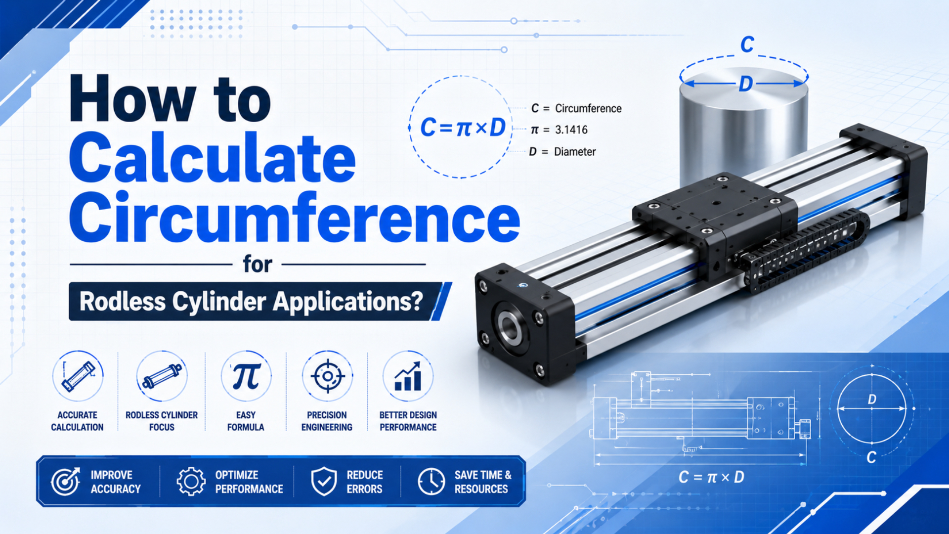
Rodless cylinder circumference is the distance around a circular bore, tube, or measured cylinder section. Use C = pi x d when you know diameter, or C = 2 x pi x r when you know radius. The harder part is choosing the right diameter before you calculate.
For a 63 mm circular bore, circumference is pi x 63 = 197.9 mm. That number can help with bore-area checks, seal discussions, surface contact estimates, and replacement measurements. It should not be confused with stroke length, carriage travel, or curved surface area.
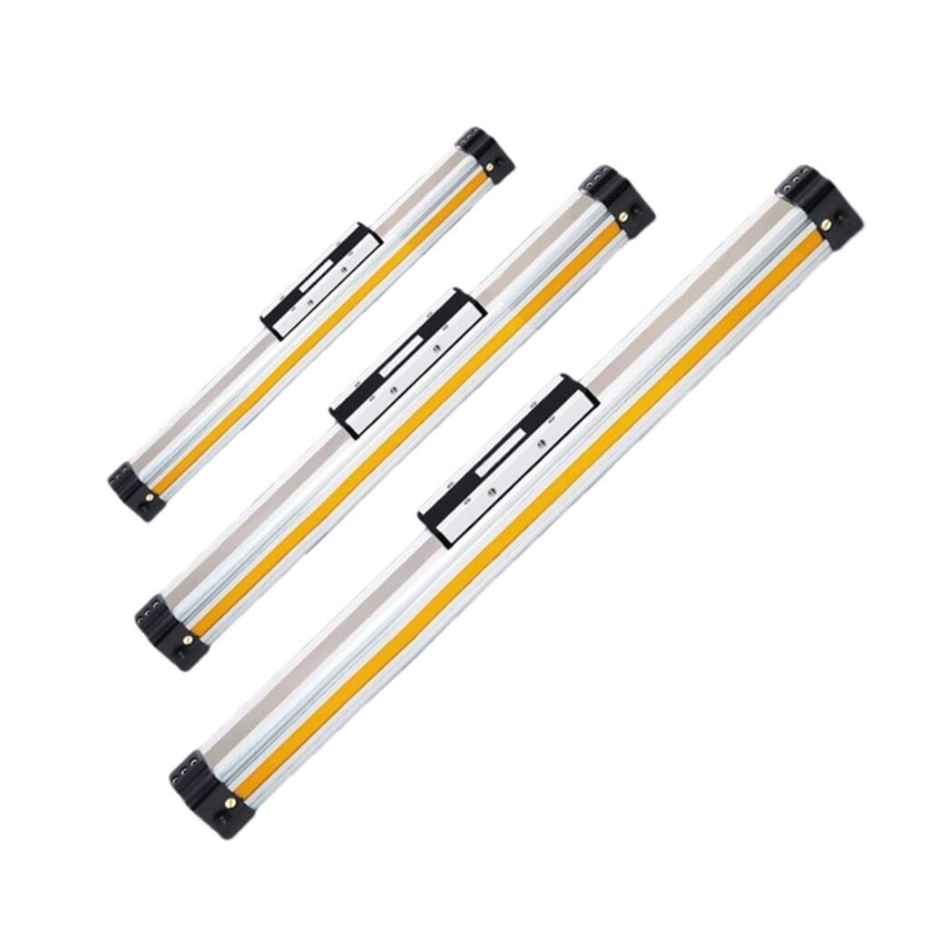
The OSP-P Series rodless cylinder shows why circumference questions need context. A rodless cylinder has a bore, an outer profile, a carriage path, sealing bands, wipers, ports, and guide options. Those are not the same circle.
Key Takeaways
- Circumference is
C = pi x d; a 63 mm bore is 197.9 mm (MathWorld, 2026).- Parker lists OSP-P bores from 10 mm to 80 mm, so bore and outside-profile circumference are separate checks.
- For RFQs, send bore, OD/profile size, stroke, carriage photos, seal-band condition, and measured pressure.
The best first question is not “what is the circumference?” It is “which circumference are we using?” A bore circumference helps with piston or seal geometry. An outside-profile circumference helps with clamps, covers, and inspection. A carriage path dimension belongs in guide and wiper selection.
Table of Contents
- What is the Basic Circumference Formula for Rodless Cylinders?
- Rodless Cylinder Diameter Zones
- How Do You Measure Diameter for Rodless Air Cylinder Circumference?
- What Tools Help Calculate Circumference in Pneumatic Applications?
- How Does Circumference Affect Rodless Cylinder Performance?
- Replacement RFQ Circumference Checks
- FAQs About Circumference Calculations
What is the Basic Circumference Formula for Rodless Cylinders?
Use C = pi x d for a circular rodless-cylinder bore or C = 2 x pi x r when radius is known. MathWorld defines circle circumference as 2 pi r = pi d, and NIST describes pi as the ratio of circumference to diameter (MathWorld, 2026; NIST, 2021).
In a rodless cylinder, this formula applies cleanly only to a circular section. The bore is circular. Some outside housings and guide profiles are not. If the outside profile is rectangular, slotted, or rail-shaped, do not force C = pi x d onto the whole profile.
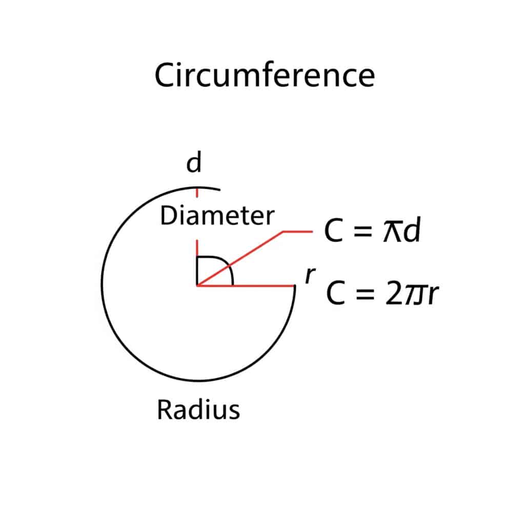
The formula diagram is useful for bore references and round OD checks. It is less useful for profile cylinders unless the drawing clearly identifies a circular feature.
Basic Formula
C = pi x d
C = 2 x pi x r
d = 2 x r
Where:
Cis circumference.dis diameter.ris radius.piis approximately 3.14159.
Common Bore Circumference Table
| Bore diameter | Radius | Bore circumference |
|---|---|---|
| 10 mm | 5 mm | 31.4 mm |
| 16 mm | 8 mm | 50.3 mm |
| 25 mm | 12.5 mm | 78.5 mm |
| 32 mm | 16 mm | 100.5 mm |
| 40 mm | 20 mm | 125.7 mm |
| 50 mm | 25 mm | 157.1 mm |
| 63 mm | 31.5 mm | 197.9 mm |
| 80 mm | 40 mm | 251.3 mm |
Those bore sizes match the OSP-P range Parker lists for its modular rodless actuator. That makes the table useful for first-pass communication, but it is not a substitute for the manufacturer’s drawing.
Quick Examples
32 mm bore: C = pi x 32 = 100.5 mm
63 mm bore: C = pi x 63 = 197.9 mm
80 mm bore: C = pi x 80 = 251.3 mm
If you only need a rough mental estimate, use diameter x 3.14. Avoid diameter x 3 unless you are checking whether a result is wildly wrong. On a 63 mm bore, d x 3 gives 189 mm, about 4.8% low.
Rodless Cylinder Diameter Zones
Measure the diameter that matches the job: bore diameter for piston and seal geometry, outside diameter for covers or clamps, and carriage or guide dimensions for load support. Parker lists OSP-P bores from 10 mm to 80 mm, plus an aluminum profile body and sealing band details (Parker OSP-P, 2026).
That one catalog family already shows three different measurement zones. The bore is an internal circular dimension. The outside body is a profile. The carriage wraps or rides along part of the body. Mixing those dimensions is how a simple circumference task turns into a wrong replacement order.
Measurement Zones
| Zone | What it answers | Use circumference formula? |
|---|---|---|
| Bore | Piston area, bore-circle reference, some seal discussions | Yes, if circular bore diameter is known |
| Outside body | Clamps, covers, packaging clearance | Only if the body section is circular |
| Seal band path | Band inspection, replacement, wiper contact | Use manufacturer data and inspection |
| Carriage or guide | Load support and moment checks | No, use guide-load ratings |
| Stroke | Travel length | No, stroke is linear distance |
When the cylinder is still in design, start with the datasheet. When the cylinder is already installed and the nameplate is gone, take photos first, then measure. A measured circumference without the actuator family can still mislead the supplier.
For product-family comparison, separate a basic profile cylinder from a DGC rodless cylinder or an MY1H precision guided rodless cylinder. Circumference will not tell you which guide package is carrying the load.
How Do You Measure Diameter for Rodless Air Cylinder Circumference?
For small circular sections, use calipers; for larger round sections, use an OD tape or circumference tape and convert back to diameter. Pi Tape publishes outside-diameter and inside-diameter tape instructions in inch and millimeter versions, including ranges from 50.80 mm to 304.80 mm (Pi Tape, 2026).
Clean the surface first. Dust, oil, burrs, tape wrinkles, and carriage damage can add just enough error to make the result look like a different bore family. If the body is a profile, measure the drawing dimensions instead of wrapping a tape around a non-circular shape.
Practical Measurement Process
- Identify whether you need bore, OD, or profile dimension.
- Clean the measured surface.
- Measure at two or three positions along the cylinder.
- Rotate the caliper measurement 90 degrees when the section is circular.
- Record the tool, unit, and location.
- Photograph the nameplate, carriage, end caps, ports, and seal band.
Caliper vs OD Tape
| Tool | Best use | Risk |
|---|---|---|
| Digital caliper | Small accessible diameters and machined parts | Jaw angle or pressure error |
| OD tape | Larger round OD checks | Tape skew or non-circular profile |
| Datasheet | New design, standard replacement, hidden bore | Wrong series or option chosen |
| Photo plus nameplate | Supplier identification | Nameplate may be missing or damaged |
In replacement work, we have found photos more useful than a single dimension. A customer may send “63 mm circumference,” but the photo reveals whether they measured a bore, a rounded cover, a carriage rail, or the outside of a sensor track.
What Tools Help Calculate Circumference in Pneumatic Applications?
A calculator is enough for the formula, but the tool chain should protect the measurement. NIST notes that pi is the ratio of circumference to diameter, while Pi Tape provides direct OD and ID tape methods, so the workflow can be either measure diameter then calculate or measure circumference then infer diameter (NIST, 2021; Pi Tape, 2026).
Use tools according to what can go wrong. A smartphone calculator does not fix a dirty cylinder surface. CAD does not fix an unknown aftermarket replacement. A caliper does not reveal whether the actuator is a magnetic, band-style, cable, or guided rodless unit.
Calculation Workflow
If diameter is known:
C = pi x d

If circumference is measured:
d = C / pi

If radius is known:
C = 2 x pi x r
Tool Selection Table
| Task | Recommended tool | Output to record |
|---|---|---|
| Quick bore circumference | Calculator with pi key | Bore diameter and calculated circumference |
| Installed round OD check | OD tape | Measured OD, circumference, tool range |
| Replacement identification | Photos plus datasheet | Series, bore, stroke, mount, carriage style |
| CAD packaging | CAD model or drawing | OD/profile dimensions and clearance |
| Seal discussion | Manufacturer seal data | Groove, band, wiper, and material details |
Do you need five decimals of pi? Usually no. For a 63 mm bore, pi = 3.14159 gives 197.920 mm, while pi = 3.14 gives 197.820 mm. The difference is 0.100 mm. Measurement choice and product identification usually matter more.
How Does Circumference Affect Rodless Cylinder Performance?
Circumference affects performance indirectly through bore size, seal contact, surface contact, and available piston area. Parker lists OSP-P maximum operating pressure at 8 bar and extend force from 47 N to 3010 N at 6 bar, but those forces come from pressure and area, not circumference alone (Parker OSP-P, 2026).
The key distinction is this: circumference grows linearly with diameter, but piston area grows with diameter squared. So a 100 mm bore has about 3.13 times the circumference of a 32 mm bore, yet about 9.77 times the bore area.
Circumference vs Area at 6 Bar
| Bore diameter | Circumference | Bore area | Theoretical force at 6 bar |
|---|---|---|---|
| 32 mm | 100.5 mm | 804 mm^2 | 483 N |
| 63 mm | 197.9 mm | 3,117 mm^2 | 1,870 N |
| 80 mm | 251.3 mm | 5,027 mm^2 | 3,016 N |
| 100 mm | 314.2 mm | 7,854 mm^2 | 4,712 N |
The force values assume 6 bar = 0.6 N/mm^2 and ignore friction, pressure drop, back pressure, cushioning, load angle, and guide losses. Use them as theory checks, not catalog guarantees.
Where Circumference Helps
Circumference helps with:
- Bore-circle communication.
- Surface contact estimates.
- Seal or band path discussions.
- OD measurement checks.
- Coating, wrap, sleeve, and guard planning when the section is circular.
Circumference does not replace:
- Piston area.
- Guide moment ratings.
- Magnetic coupling force.
- Seal-band service data.
- Pressure and flow measurements under motion.
For the surface-area side of the topic, keep this page separate from the pipe surface area calculation guide. That page covers pi x D x L; this one stays focused on rodless cylinder circular sections and replacement measurements.
For broader selection context, compare this measurement article with how a rodless air slide works and the rodless actuator family guide. Those pages cover force transfer and control architecture, while this page stays on circumference and measurement.
Replacement RFQ Circumference Checks
Include circumference or diameter in a replacement RFQ when the nameplate is missing, the bore is uncertain, or the supplier must distinguish similar rodless-cylinder families. SMC lists MY1B mechanically jointed rodless-cylinder data such as 0.2 to 0.8 MPa pressure and 100 to 1000 mm/s centralized-piping piston speed (SMC MY1B catalog, 2025).
Those catalog values depend on the actual series and option package. A circumference measurement can narrow the search, but it cannot identify the guide type, shock absorber, stroke adjustment unit, sensor track, or seal-band condition by itself.
RFQ Measurement Checklist
Send these details:
- Current model number or nameplate photo.
- Bore or measured circular section diameter.
- Stroke length.
- Overall body/profile dimensions.
- Carriage width and guide style.
- Port size and fitting orientation.
- Sensor type and cable position.
- Photos of both end caps.
- Photos of seal band, wiper, and carriage.
- Measured pressure during motion.
- Load mass, load offset, and mounting orientation.
If you only send circumference, the supplier still has to guess the actuator family. If you send circumference plus carriage photos and stroke, the quote can quickly move from “similar-looking cylinder” to “correct replacement package.”
Replacement Mistakes to Avoid
| Mistake | Result | Better check |
|---|---|---|
| Measuring outside profile as bore | Wrong force estimate | Use nameplate or catalog bore |
| Measuring around a non-circular body | Meaningless circumference | Use drawing dimensions |
| Ignoring seal-band condition | Repeat leakage after replacement | Photograph band and wiper |
| Omitting stroke | Correct bore, wrong length | Measure travel end to end |
| Omitting pressure | Good dimensions, poor motion | Measure pressure while moving |
CAGI recommends a well-designed compressed-air system keep pressure drop from compressor discharge to point of use under 10%; it also notes every 2 psig of excess pressure can add about 1% compressor power use (CAGI, 2026). That is why a replacement quote should include operating pressure, not only dimensions.
If the quote also needs thrust checks, pair the circumference data with pneumatic cylinder force calculation. Circumference can identify a round section, but force still needs pressure and area.
FAQs About Circumference Calculations
What is the easiest way to calculate circumference?
Use C = pi x d. If the rodless cylinder bore is 63 mm, circumference is 3.14159 x 63 = 197.9 mm. Use this only for circular sections such as bore references. For a profiled body or carriage, use the manufacturer’s drawing.
How do you measure diameter for circumference calculations?
Use calipers on small circular sections and an OD tape on larger round sections. Measure at more than one location, clean the surface first, and note whether you measured bore, outside body, or another round feature. Pi Tape publishes OD and ID tape instructions for this kind of measurement workflow.
Is rodless cylinder circumference the same as stroke length?
No. Circumference is the distance around a circular section. Stroke length is the straight travel distance of the piston or carriage. A Parker OSP-P rodless cylinder can have a 63 mm bore and a much longer stroke, so the two dimensions answer different questions.
Does circumference determine rodless cylinder force?
No. Force comes from pressure times piston area, and piston area is pi x d^2 / 4. Circumference can help identify the bore, but it is not the force formula. A 63 mm bore at 6 bar is about 1,870 N before losses.
What should I send for a rodless cylinder replacement quote?
Send bore or measured diameter, calculated circumference if useful, stroke, model number, body/profile dimensions, carriage photos, end-cap photos, port location, sensor type, seal-band condition, load, mounting orientation, and pressure during motion. That package is stronger than a circumference value alone.
Sources
- Wolfram MathWorld, “Circumference”, https://mathworld.wolfram.com/Circumference.html. Retrieved 2026-06-04. Supports
C = 2 pi r = pi d. - NIST, “Circumference, Area and Volume”, https://www.nist.gov/pml/owm/circumference-area-and-volume. Retrieved 2026-06-04. Supports pi as the ratio of circumference to diameter.
- Pi Tape, “Video and PDF Instructions”, https://pitape.com/resources/downloads-page/. Retrieved 2026-06-04. Supports OD and ID tape measurement workflow.
- Parker Hannifin, “OSP-P Rodless Cylinders”, https://discover.parker.com/OSPPSeries. Retrieved 2026-06-04. Supports OSP-P bore range, pressure, force, sealing band, profile body, and guide context.
- AutomationDirect, “Rodless Cylinders Provide a Compact Pneumatic Linear Motion Option”, https://library.automationdirect.com/rodless-cylinders-provide-compact-pneumatic-linear-motion/. Retrieved 2026-06-04. Supports internal piston and external carriage explanation.
- SMC, “MY1B Mechanically Jointed Rodless Cylinder catalog”, https://www.smcworld.com/catalog/BEST-5-2-en/pdf/2-p1211-1325-my1b_en.pdf. Retrieved 2026-06-04. Supports pressure, piston-speed, and stroke-adjustment context.
- CAGI, “Working With Compressed Air”, https://www.cagi.org/working-with-compressed-air/. Retrieved 2026-06-04. Supports pressure-drop and compressor power context.
- Enfield Technologies, “S2 Positioning - Better Rodless Cylinder Positioning”, https://www.enfieldtech.com/portfolio/Position/better-rodless-cylinder-positioning. Retrieved 2026-06-04. Supports the embedded rodless cylinder positioning video context.