

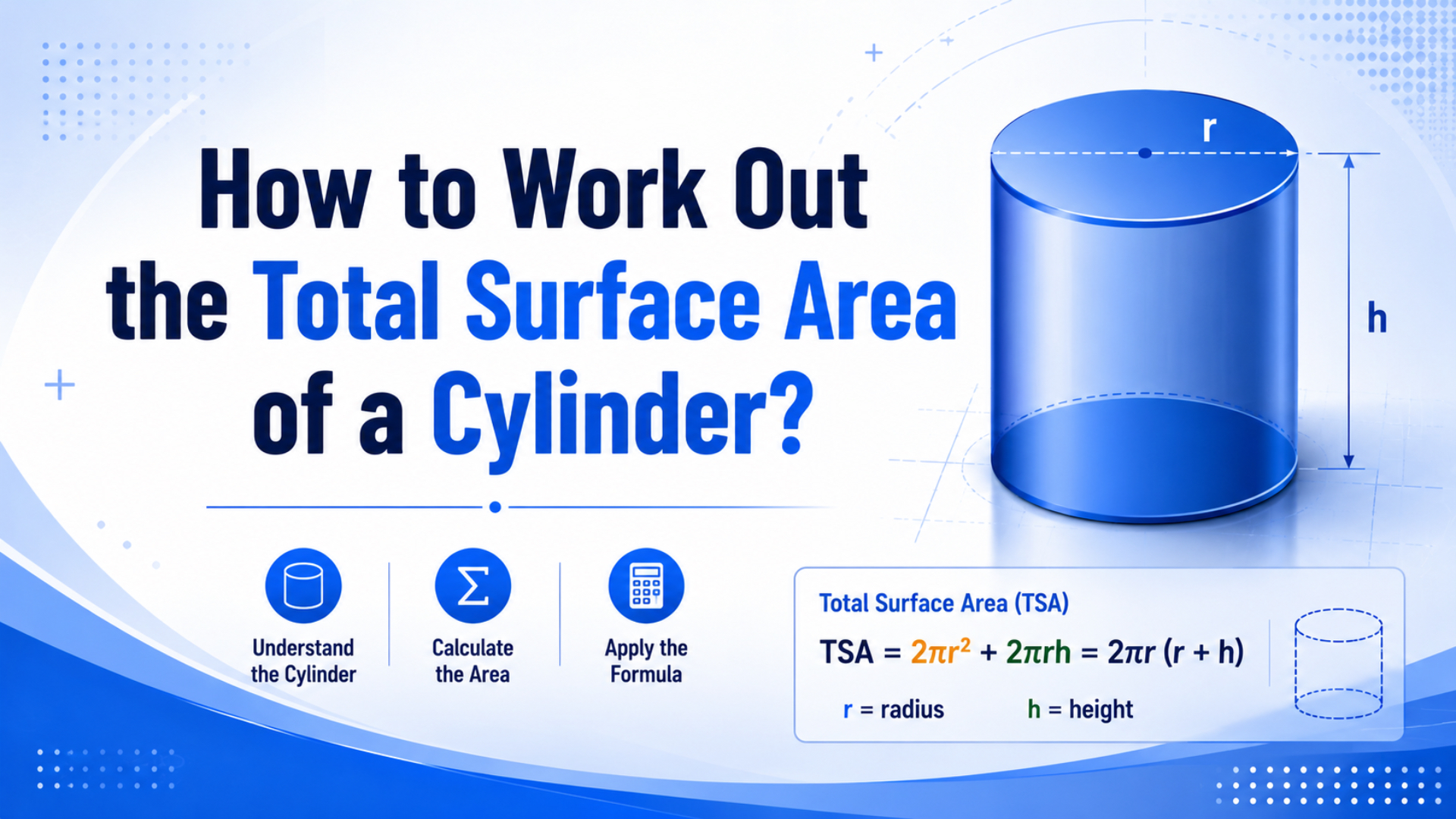
To work out the total surface area of a cylinder, add the area of the two circular ends to the curved side wall. Formula: A = 2*pi*r^2 + 2*pi*r*h, where r is radius and h is height or length.
For pneumatic cylinder sizing, that is only half the story. Total surface area helps with coating, cleaning, heat exposure, and outside contact area. Force output uses piston area, A = pi*r^2, not total surface area. Mixing those two areas is the fastest way to oversize or undersize an actuator.
Key Takeaways
- OpenStax gives total cylinder surface area as
S = 2*pi*r^2 + 2*pi*r*hfor radiusrand heighth.- Pneumatic force uses effective piston area, not total outside surface area.
- At 6 bar, a 32 mm bore has about 804 mm2 piston area and about 483 N theoretical force before losses.
What Is the Formula for Total Cylinder Surface Area?
Cylinder total surface area is S = 2*pi*r^2 + 2*pi*r*h; OpenStax explains the formula as two circular ends plus the lateral surface of the cylinder (OpenStax, 2023). Apply this formula when you need the outside area of a solid cylindrical body.
Here is the clean breakdown:
Area of one circular end = pi*r^2
Area of two circular ends = 2*pi*r^2
Curved side area = circumference x height = 2*pi*r*h
Total surface area = 2*pi*r^2 + 2*pi*r*h
For a cylinder with 16 mm radius and 1000 mm length, the two ends total about 1,608 mm2. Curved side wall area is about 100,531 mm2. Total surface area is about 102,139 mm2, or 0.102 m2.
That example shows why length matters. On a long actuator body, the side wall dominates total surface area. End caps matter mathematically, but coating, cleaning, and heat exposure usually live on the long curved surface.
Which Surface Area Matters in Pneumatic Cylinder Sizing?
Pneumatic force sizing uses piston area, not total surface area; NASA states that pressure force equals pressure times surface area, and in a cylinder that active area is the piston face (NASA Glenn, 2026). For extension force, start with A = pi*r^2.
That distinction saves real mistakes. If you use total outside surface area in a force calculation, the answer can be dozens or hundreds of times too high on a long cylinder. Air pressure is not acting on the outside tube coating. It acts on the piston face inside the bore.
Match the area name to the engineering job:
| Area type | Formula | Use it for |
|---|---|---|
| Piston area | pi*r^2 |
Extension force and bore sizing |
| Rod-side effective area | piston area - rod area |
Retract force on single-rod cylinders |
| Lateral surface area | 2*pi*r*h |
Tube coating, cleaning, heat exposure |
| Total surface area | 2*pi*r^2 + 2*pi*r*h |
Total outside area of a closed cylinder shape |
In actuator sizing reviews, I treat “surface area” as an unsafe phrase until the drawing says which surface. Bore face, rod-side annulus, tube outside, bore wall, and end-cap area all answer different engineering questions.
How Do You Calculate Piston Area and Force?
AutomationDirect says cylinder force is calculated from effective piston area multiplied by differential pressure, and its sizing guidance adds 25% force margin for friction, pressure drop, and other factors (AutomationDirect, 2026). Sizing math starts simple, but the design margin is practical.
In metric pneumatic work, keep the units consistent:
1 bar = 0.1 N/mm2
6 bar = 0.6 N/mm2
Piston area = pi*bore^2/4
Theoretical force = pressure x piston area
Example for a 32 mm bore at 6 bar:
Piston area = pi*(32^2)/4 = 804 mm2
Pressure = 0.6 N/mm2
Theoretical force = 0.6 x 804 = 482 N
That does not mean the machine can lift or push 482 N reliably. Seal friction, guide drag, tubing loss, valve restriction, back pressure, acceleration, and mounting geometry reduce the usable number. This is why many sizing workflows add a margin after the theoretical calculation.
On single-rod cylinders, retract force is lower than extend force because the rod takes away active area. Rodless cylinders do not have an external piston rod, but they still need coupling, seal, guide, and carriage-load checks before the force number is useful.
What Are the Most Common Calculation Mistakes?
CAGI’s pressure-drop brief says well-designed compressed-air systems should have no more than 10% pressure drop between compressor discharge and any point of use (CAGI, 2026). That matters because cylinder force should use pressure at the actuator port during motion, not only the regulator setting.
Mistake one is using diameter as radius. If the bore is 32 mm, the radius is 16 mm. Squaring 32 instead of 16 makes the piston area 4 times too large.
Mistake two is mixing total surface area with piston area. Total surface area may be useful for coating a cylinder body, but it does not calculate push force.
Mistake three is ignoring unit conversion. A useful metric shortcut is bar x cm2 x 10 = N. If you work in mm2 instead, convert bar to N/mm2: 6 bar is 0.6 N/mm2.
Mistake four is sizing from static pressure. A gauge reading 6 bar at rest may fall during fast motion if the valve, fitting, tubing, filter, or regulator is too small. Pressure under flow is the number that matters.
When a force complaint reaches the RFQ desk, I ask for pressure during motion before I ask for a larger bore. A bigger cylinder with the same undersized valve can still move poorly.
Worked Example for a Rodless Cylinder Body
Parker’s OSP-P rodless-cylinder catalog lists 10-80 mm bores, standard strokes to 6000 mm, 8 bar maximum operating pressure, and theoretical force values at 6 bar (Parker OSP-P catalog, 2025). Those catalog values line up with pressure times piston area in selection.
Take a 32 mm bore, 1000 mm stroke rodless cylinder body. Use 16 mm as radius for piston-area and simple outside-area examples if the outside body diameter is being approximated. In a real quote, the actual profile dimensions from the catalog drawing should drive the outside-area calculation.
Piston area = pi*16^2 = 804 mm2
Theoretical force at 6 bar = 804 x 0.6 = 482 N
Total surface area of a simple 32 mm diameter x 1000 mm cylinder shape:
2*pi*16^2 + 2*pi*16*1000 = 102,139 mm2
Notice the scale difference. The outside surface area is about 127 times larger than the piston area in this simplified example. That is exactly why the wrong area creates wildly wrong force results.
When Does Total Surface Area Matter in Pneumatics?
Total surface area matters when the surface itself is the engineering problem; OpenStax’s formula counts the outside of the cylinder, while CAGI’s 10% pressure-drop guidance reminds pneumatic designers to separate surface checks from flow and pressure checks (OpenStax, 2023; CAGI, 2026). Pick each calculation for the right job.
Choose total or lateral surface area for coating estimates, washdown exposure, corrosion protection, cleaning contact, labeling, inspection planning, and rough heat-exposure comparisons. If a cylinder sits in a dusty, wet, or food-adjacent area, outside area can matter for maintenance.
Bore area drives pneumatic force. Bore volume drives air consumption. Tubing inside diameter drives flow area. Pipe or tube surface area supports cleaning and heat-transfer checks. These are nearby calculations, but they are not interchangeable.
Rodless cylinders add another layer: the external carriage and guide surfaces. The tube may have a calculated outside area, but the carriage, sealing strip, guide rail, and wiper contact surfaces often decide the real maintenance burden.
What Should You Send for a Sizing or Replacement RFQ?
Parker’s OSP-P catalog publishes bore, stroke, pressure, cushioning, and theoretical force tables, but a correct replacement still needs application data beyond the geometry (Parker OSP-P catalog, 2025). Send both the calculation inputs and the machine conditions before reliable selection and matching.
On a surface-area or coating question, send cylinder outside dimensions, tube profile, stroke, exposed length, material, finish requirement, washdown condition, and whether the end caps count in the coating estimate.
On a force or bore question, send required load force, moving mass, stroke, pressure at the actuator during motion, cycle rate, orientation, valve size, tubing size, stop method, and whether the cylinder pushes, pulls, lifts, clamps, or carries an offset load.
With a rodless-cylinder replacement, add carriage dimensions, guide style, sensor type, port location, mounting hole pattern, model label photos, and failure symptoms. A surface-area calculation can help with the drawing, but the replacement decision still needs load path and pressure data.
My RFQ shortcut is to ask for three areas before model matching: piston area for force, rod-side annulus if it is a single-rod cylinder, and exposed outside area if the customer is asking about coating, washdown, or corrosion. It keeps the conversation from drifting.
Conclusion
Cylinder total surface area is 2*pi*r^2 + 2*pi*r*h, while pneumatic force uses piston area pi*r^2; NASA’s pressure relation explains why pressure must act on the correct surface (NASA Glenn, 2026). Keep those two areas separate and the sizing conversation gets cleaner.
Choose total surface area when the outside surface matters. Choose piston area when force matters. Choose rod-side effective area when retract force matters. Choose flow area when velocity or pressure drop matters.
That is the practical answer. The formula is simple, but the naming is where mistakes start. Ask which surface is being measured before you calculate.
FAQs About Cylinder Surface Area
Cylinder surface area questions usually mix geometry and pneumatic force; OpenStax gives the total surface formula, while AutomationDirect and NASA connect cylinder force to effective area and pressure (OpenStax, 2023; AutomationDirect, 2026; NASA Glenn, 2026). The short answers below separate those jobs.
What is the formula for total surface area of a cylinder?
The total surface area formula is A = 2*pi*r^2 + 2*pi*r*h, where r is radius and h is height or length. The first term counts the two circular ends. The second term counts the curved side wall.
Is total surface area the same as piston area?
No. Total surface area is the outside area of a closed cylinder shape. Piston area is the circular bore area that pressure acts on inside the cylinder. Pneumatic force sizing uses piston area, pi*r^2, not total surface area.
How do I calculate pneumatic cylinder force from area?
Use F = P x A, where P is pressure and A is effective piston area. In metric units, 6 bar equals 0.6 N/mm2. A 32 mm bore has about 804 mm2 piston area, so theoretical force is about 482 N before losses.
Why does a larger bore increase force so quickly?
Bore force rises with area, and area depends on radius squared. Doubling bore diameter gives about 4 times the piston area, before friction and pressure loss. That is why small bore changes can have a large effect on force and air consumption.
When should I calculate lateral surface area only?
Use lateral surface area, 2*pi*r*h, when the two ends do not matter. Examples include estimating tube coating, wrap labels, exposed side-wall cleaning area, or heat exposure on the cylindrical body. Include the two ends only when they are also exposed or coated.
What data should I send for a cylinder sizing quote?
Send bore or required force, stroke, available pressure during motion, load mass, movement direction, speed target, valve and tubing size, mounting orientation, stop method, and environment. For rodless cylinders, also send carriage offset, guide type, sensor style, and failure photos if it is a replacement.
Sources
-
OpenStax: Volume and Surface Area, cylinder total surface area formula and geometry explanation. Retrieved 2026-06-04.
-
NASA Glenn Research Center: Air Pressure, pressure force relationship used to connect pressure and active area. Retrieved 2026-06-04.
-
AutomationDirect: How to Select a Pneumatic Cylinder, cylinder sizing by required force and available pressure, plus margin discussion. Retrieved 2026-06-04.
-
AutomationDirect: Pneumatics In Depth, Cylinder Sizing, effective surface area and differential pressure relationship for extension force. Retrieved 2026-06-04.
-
Parker: OSP-P Pneumatic Rodless Cylinders and Linear Guides catalog, bore sizes, stroke data, pressure limits, and theoretical force tables. Retrieved 2026-06-04.
-
CAGI: Technical Brief on Pressure Drop, compressed-air pressure-drop guidance and 10% point-of-use design benchmark. Retrieved 2026-06-04.