

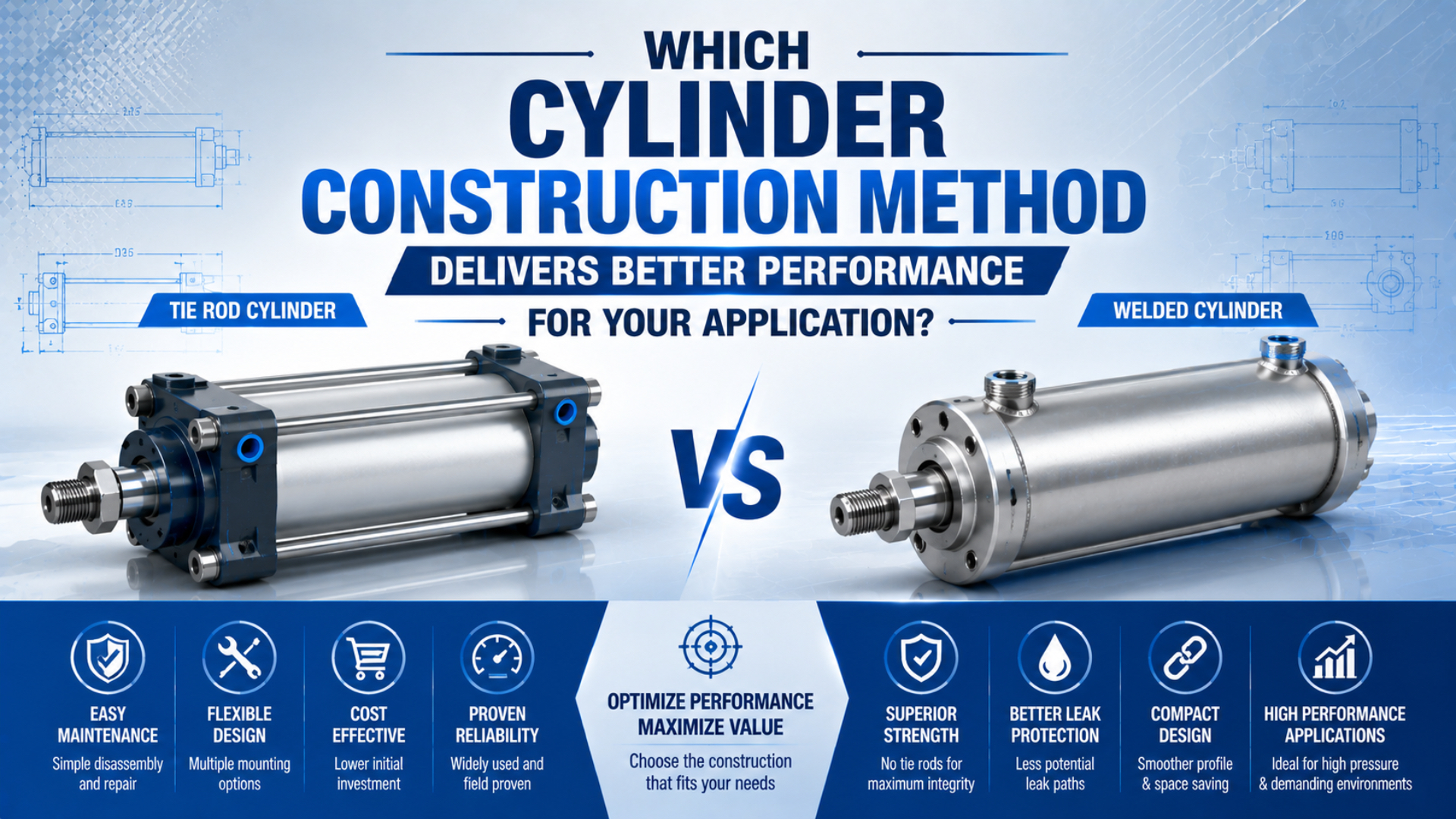
Neither profile nor tie-rod cylinder construction is universally better. In matched 63 mm AVENTICS ISO 15552 examples, the PRA profile cylinder and TRB tie-rod cylinder both list 1,960 N extension force at 6.3 bar and a 10 bar maximum working pressure (AVENTICS PRA; AVENTICS TRB). The real choice is about envelope, sensor mounting, exposure, service method, and configuration evidence.
Key Takeaways
- A matched 63 mm profile and tie-rod pair both deliver 1,960 N at 6.3 bar.
- Construction changes the external package and service route, not the force equation.
- Confirm the exact drawing, repair instructions, environment, and sensor arrangement before choosing.
Profile vs Tie-Rod Cylinders: The Short Answer
The 63 mm AVENTICS PRA profile example and TRB tie-rod example both specify 1,765 N retraction force, 1,960 N extension force at 6.3 bar, and 10 bar maximum pressure (AVENTICS PRA; AVENTICS TRB). That matched result rules out a blanket performance winner.
Treat construction as a packaging and lifecycle decision after bore, stroke, pressure, load direction, speed, cushioning, and mounting are established. A profile body may give you a cleaner rectangular envelope and integrated switch slots. An exposed tie-rod design may offer a familiar clamped assembly and convenient external attachment points. Those are useful differences, but they aren’t substitutes for an application calculation.
The quickest decision rule is simple: if two candidates meet the required force, stroke, mount, speed, and environment, choose the one whose external geometry and documented service route reduce machine-level risk. If either candidate misses a configured interface, its construction advantages no longer matter.
What Actually Changes With the Construction Method?
ISO 15552 covers a 10 bar dimensional series with bores from 32 to 320 mm, but it standardizes basic, mounting, and accessory dimensions rather than one mandatory body architecture (ISO 15552:2018, confirmed 2025). Profile and tie-rod cylinders can therefore share an interface family while retaining different external structures.
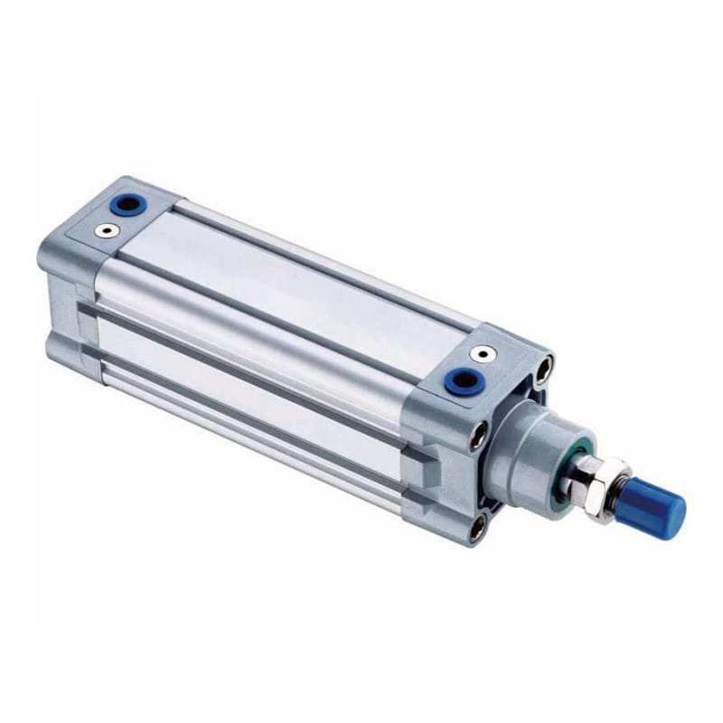
Profile cylinder construction is an arrangement that usually places the working barrel inside an extruded aluminum body with longitudinal grooves or sensor slots. The exact end-cap retention method is model-specific. It shouldn’t be described as automatically seamless, leak-free, or non-repairable.
Tie-rod cylinder construction is an arrangement that uses external rods and fasteners to clamp separate end caps around the barrel. That doesn’t mean the barrel must be welded, nor does it prove every unit can be repaired in the field. The manufacturer’s assembly and repair instructions still control the safe service method.
Why Doesn’t Construction Create More Cylinder Force?
The matched 63 mm examples produce the same 1,960 N extension force at the same 6.3 bar basis because pneumatic force follows pressure and effective piston area (AVENTICS PRA; AVENTICS TRB). A profile extrusion or four external tie rods doesn’t add piston area.
For an ideal extension calculation:
Here, is extension force, is effective pressure at the cylinder after line and valve losses, and is piston bore. Retraction uses , where is rod diameter. Actual usable force must also allow for friction, pressure variation, acceleration, and the application’s safety margin.
What happens if you replace a 63 mm tie-rod cylinder with a 63 mm profile cylinder at the same effective pressure? The theoretical piston force doesn’t rise. If more force is required, revisit bore or pressure within the lowest-rated component limit. The Cylinder Force Calculator helps compare those inputs without treating construction as a multiplier.
Are Pressure Rating, Rigidity, and Rod Buckling Construction Advantages?
Parker’s ISO 15552 P1F family includes both smooth-profile and tie-rod designs, with the technical catalogue listing a 1 to 10 bar operating range for the family (Parker P1F technical catalogue). Pressure rating is therefore a series and configuration property, not a profile-body privilege.
Rigidity also needs a defined load path. The cylinder tube and end retention matter for pressure containment, but side load, mount alignment, guide stiffness, rod diameter, and unsupported length can dominate machine behavior. If the rod is carrying a cantilevered moment or binding through misalignment, changing the barrel exterior won’t solve the root cause. Review cylinder deflection in cantilevered mounts and side-load mitigation separately.
Rod buckling is a compressive-column check. Parker’s catalogue selects rod diameter against maximum piston thrust, stroke or buckling length, and mounting condition, with a recommended safety factor range of 3.5 to 5. The Pneumatic Cylinder Rod Buckling Calculator can screen that risk, but it still needs the actual rod, stroke, mount, and load.
Where Does Profile Construction Usually Help?
The AVENTICS PRA example combines an ISO 15552 profile body, magnetic piston, and sensor compatibility in a 63 mm, 10 bar configuration (AVENTICS PRA). Profile construction tends to help when the machine benefits from an orderly rectangular envelope, integrated grooves, and fewer exposed external rods.
Those features can matter in a guarded assembly cell where a switch must slide along the barrel without extra brackets. A smoother exterior may also be easier to wipe than exposed rods, nuts, and recesses. Still, “smooth” isn’t the same as hygienic certification. Washdown suitability depends on materials, ingress protection, seals, fasteners, lubricants, drainage, chemical compatibility, and installation orientation.
Profile construction can also simplify CAD packaging, but don’t assume every profile cylinder is shorter or narrower. Port orientation, cushioning adjusters, magnet sensors, cable exits, mounting feet, and rod accessories can set the true envelope. In our experience, a 3D model with the installed accessories exposes conflicts that a bare-cylinder catalogue silhouette misses.
Where Do Exposed Tie Rods Usually Help?
AVENTICS publishes one repair instruction covering PRA and TRB cylinders, including model-specific tie-rod assembly steps and tightening torques (AVENTICS PRA/TRB repair instructions). That evidence shows why serviceability must be judged from the exact manual: both architectures can have documented repair routes, but the work sequence differs.
Exposed tie rods can make the clamped structure visually clear and can support supplier-specific switch brackets or accessories. In our experience, maintenance teams familiar with the design may prefer it when qualified technicians, spare seals, torque data, clean assembly space, and post-repair tests are available. Is that automatically the lowest-cost choice? No. Access time, contamination risk, downtime, and replacement availability still matter.
Tie rods also create external surfaces and gaps that may be undesirable around debris, frequent wiping, close guarding, or snag-sensitive cabling. Conversely, a protected machine zone may make those concerns negligible. If repair economics drive the choice, use the exact failure and parts evidence in a repair-versus-replace assessment rather than assigning a universal service-life advantage.
A Seven-Factor Selection Matrix
The ISO 15552 scope spans 32 to 320 mm bores and a 10 bar series, yet those standardized dimensions don’t select the body style for you (ISO 15552:2018, confirmed 2025). A useful matrix separates standards-controlled interfaces from supplier-controlled construction and application-controlled acceptance criteria.
| Selection factor | Evidence to request | Profile tends to fit when | Tie-rod tends to fit when |
|---|---|---|---|
| Installed envelope | Option-specific 2D/3D drawing with fittings, sensors, mounts, and cable bend | A smooth rectangular body or integrated slot reduces interference | External rods and brackets fit within the available guard space |
| Sensors | Approved switch list, groove or bracket details, sensing range | Integrated grooves simplify sensor positioning | External bracket hardware is preferred or already standardized |
| Environment | Material, coating, IP, seal, lubricant, and cleaner compatibility | Fewer exposed rods make routine exterior cleaning simpler | The area is protected and external gaps don’t create a maintenance issue |
| Service route | Repair manual, kit number, torque table, test procedure | The exact profile series has supported repair or fast replacement | The exact tie-rod series supports qualified disassembly and stocked parts |
| Stroke and bore | Catalogue range plus buckling calculation | Required size lies in the supplier’s profile range | Long stroke or large bore is better supported in the tie-rod range |
| Retrofit | ISO family plus full configured drawing comparison | All interfaces and accessories clear without modification | Existing brackets, switches, and service practice favor the tie-rod package |
| Pressure and force | Rated pressure, bore, rod, force basis, valve losses | The selected profile SKU meets the calculated duty | The selected tie-rod SKU meets the same calculated duty |
In practice, some rows point in opposite directions. Weight the matrix by failure consequence instead of counting checkmarks. A sensor-bracket preference shouldn’t outweigh an incompatible cleaner, an undersized rod, or an inaccessible emergency replacement. For site-wide decisions, connect the matrix to a controlled pneumatic cylinder standardization plan.
Can an ISO 15552 Profile Cylinder Replace a Tie-Rod Cylinder Directly?
ISO 15552 standardizes basic, mounting, and accessory dimensions for detachable mountings across 32 to 320 mm bores, but it doesn’t promise identical ports, rod threads, cushions, sensors, materials, or option codes (ISO 15552:2018, confirmed 2025). A shared standard is the start of a retrofit check, not its completion.
Use this evidence stack before releasing a replacement:
- Match the standard family, bore, stroke, mounting style, and mounting dimensions.
- Compare the full configured drawings, including retracted and extended length, rod thread, ports, cushion adjusters, sensor grooves, and accessory clearances.
- Confirm pressure, temperature, materials, seals, lubricant, environment, speed, side load, and buckling limits.
- Verify switches, connectors, cable routes, fittings, flow controls, and guards on the actual machine.
- Inspect the first article, run a controlled functional test, and freeze the approved part code and drawing revision.
Would “ISO 15552” alone catch a cable connector that strikes a guard? It wouldn’t. The safer method is the four-layer approval process in our guide to ISO 15552 cylinder interchangeability: dimensional fit, configured interfaces, functional equivalence, and validated release.
Conclusion: Select the Evidence, Then the Construction
Matched 63 mm AVENTICS profile and tie-rod examples both publish 1,960 N extension force at 6.3 bar and 10 bar maximum working pressure (AVENTICS PRA; AVENTICS TRB). That comparison is more useful than a generic claim that one construction is stronger, faster, or longer-lived.
Start with the motion and load. Then verify pressure, mounting, guidance, cushioning, sensors, environment, and maintenance capability. Once both candidates pass those gates, construction becomes a practical choice: profile for the external package and integrated features it can offer, or tie rod for the exposed clamped architecture and service approach supported by its documentation.
Profile vs Tie-Rod Cylinder FAQs
ISO 15552 defines a 10 bar dimensional series from 32 to 320 mm bores, but its scope doesn’t declare a universal construction winner (ISO 15552:2018, confirmed 2025). These five answers separate force and pressure facts from model-specific packaging, maintenance, environment, and retrofit decisions.
Do profile cylinders produce more force than tie-rod cylinders?
No. A matched 63 mm AVENTICS PRA profile cylinder and TRB tie-rod cylinder both list 1,960 N extension force at 6.3 bar. Force comes from effective pressure and piston area, with friction and dynamic allowances reducing usable output. Construction should not be entered as a force multiplier.
Are profile cylinders rated for higher pressure?
Not inherently. The matched AVENTICS 63 mm PRA profile and TRB tie-rod examples both list a 10 bar maximum working pressure. Check the exact series, bore, stroke, temperature, medium, and options. Never transfer the rating from one supplier or configuration to another because the exterior looks similar.
Are tie-rod cylinders always easier to repair?
No. AVENTICS publishes repair instructions covering both PRA profile and TRB tie-rod cylinders, with bore-specific assembly and torque details. Repairability depends on the exact model, manual, parts, technician capability, cleanliness, and post-repair testing. Exposed tie rods alone don’t prove that field repair is safe or economical.
Which construction is better for washdown or clean areas?
Neither body style proves washdown suitability. A profile exterior may present fewer exposed rods and gaps, but the decision also requires material, coating, ingress, seal, lubricant, drainage, cleaner, temperature, and corrosion evidence. Approve the complete configured cylinder and installation against the site’s sanitation and chemical requirements.
Can an ISO 15552 profile cylinder replace a tie-rod cylinder directly?
Sometimes, but ISO 15552 alone is insufficient. It standardizes defined basic, mounting, and accessory dimensions across 32 to 320 mm bores. You must still compare stroke, overall length, ports, rod end, cushions, sensors, materials, accessories, environment, and performance, then validate the configured replacement on the machine.
Sources and technical references
- ISO 15552:2018, confirmed 2025. Used for the 10 bar dimensional series, 32 to 320 mm bore scope, and standardized basic, mounting, and accessory dimensions.
- AVENTICS PRA profile cylinder, R412014214. Used for the 63 mm bore, 1,765 N retract force, 1,960 N extend force at 6.3 bar, and 10 bar maximum pressure.
- AVENTICS TRB tie-rod cylinder, R480163018. Used for the matched 63 mm bore, force basis, forces, and 10 bar maximum pressure.
- AVENTICS PRA/TRB repair instructions. Used for model-specific assembly, repair sequence, and tie-rod tightening evidence.
- Parker P1F ISO cylinder technical catalogue. Used for smooth-profile and tie-rod family options, operating pressure range, and rod-buckling selection factors.
- How to Select a Pneumatic Cylinder from AutomationDirect, uploaded 2021-04-16. Used as the embedded 2 minute 18 second cylinder-selection overview.