

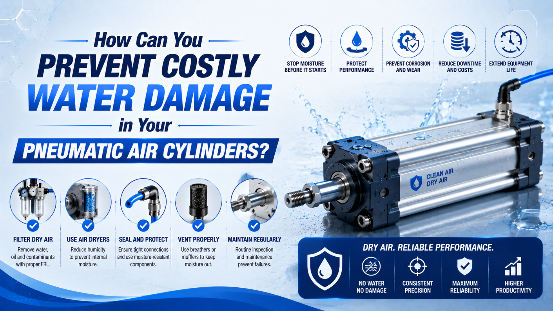
Prevent water damage in pneumatic air cylinders by controlling moisture at its source, proving the pressure dew point at the machine inlet, removing condensate before it can travel downstream, and protecting the actuator from external washdown or weather. A wet cylinder is evidence of a system or enclosure problem, not automatically a reason to buy a different cylinder.
The most important distinction is where the water came from. Internal condensation usually points to wet supply air, a failed drain, an overloaded dryer, or a cold section of piping. Water entering around a rod, end cap, port, or sealing band points instead to an external-ingress problem. The corrective actions are different.
Key Takeaways
- Diagnose internal supply-air moisture separately from rain, washdown, coolant, or process-water ingress.
- Specify pressure dew point at the machine inlet and keep it below the coldest surface in the air route.
- Separators, filters, drains, and dryers perform different jobs; an FRL does not replace a properly selected dryer.
- Inspect the failed cylinder and the air system before deciding whether to repair or replace the actuator.
How Does Water Reach a Pneumatic Cylinder?
Water reaches a cylinder through two primary routes: it travels inside the compressed-air supply, or it crosses the actuator’s external boundary. Parker explains that cooling compressed air below its dew point causes water vapor to condense (Parker Drying Compressed Air Guide, 2017). That mechanism can occur far downstream of the compressor.
Internal supply-air moisture
Internal supply-air moisture is water vapor, aerosol, or liquid carried through the compressed-air route toward the actuator. Ambient air always carries some water vapor. Compression concentrates that vapor, and aftercooling turns part of it into liquid. Separators and drains should remove the bulk liquid; a dryer lowers the remaining vapor content. Water can still reach a cylinder when:
- an aftercooler, receiver, separator, or automatic drain is not working correctly;
- the dryer is bypassed, overloaded, undersized, or operating outside its rated inlet conditions;
- wet legacy pipework releases stored condensate after the dryer has been repaired;
- a distribution line has low points, poor slope, or bottom-fed drops that carry liquid toward the machine;
- the machine inlet or actuator cools below the pressure dew point;
- a local filter bowl fills because its drain is blocked or isolated.
The pattern may be intermittent. A machine can run dry during a warm afternoon and receive liquid water after a cold shutdown, a high-flow production peak, or a failed receiver drain.
External ingress
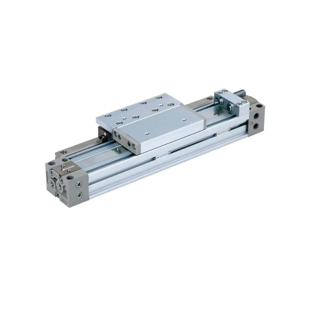
External ingress means water crossing the actuator’s outside boundary rather than arriving through the air ports. It can come from washdown, rain, coolant spray, condensation on the actuator body, or process liquid. It may pass a damaged rod seal, worn scraper, loose port fitting, end-cap joint, cable entry, or sealing band. Retraction can carry liquid and debris across a rod seal, while a rodless cylinder may have additional external interfaces defined by its design.
Do not treat an ingress-protection rating as proof that an assembled machine is protected in every orientation. Ports, fittings, sensors, mounting surfaces, pressure equalization, and the direction of a spray can change the real boundary. Check the cylinder manufacturer’s installation and environmental limits for the exact model.
[UNIQUE INSIGHT] If several cylinders on one branch show similar internal rust, investigate the air supply first. If damage is concentrated on the exposed side of one actuator or follows a washdown direction, investigate the external boundary first. The spatial pattern often separates a shared utility fault from a local enclosure fault.
What Evidence Separates Wet Supply Air From External Ingress?
Start with evidence from the failed component and from the live air system. ISO 8573-1 classifies compressed-air purity by particles, water, and oil independently of the measurement location (ISO 8573-1:2010, 2010). Your inspection therefore needs named sampling points, operating conditions, and photographs rather than a single statement that the plant has “dry air.”
| Evidence | More consistent with wet supply air | More consistent with external ingress | Next check |
|---|---|---|---|
| Similar corrosion in multiple actuators or valve manifolds | Yes | Less likely | sample branch air and inspect upstream drains |
| Water in receiver, separator, or local filter bowl | Yes | No | test drain operation and dryer performance |
| Damage concentrated near the rod end or exposed sealing interface | Possible | Yes | inspect scraper, rod, band, orientation, and spray path |
| Corrosion on both internal end caps with rust particles in ports | Yes | Possible | inspect supply tubing and upstream pipe debris |
| External staining around a loose fitting or port | Less likely | Yes | pressure-test fitting and improve shielding |
| Moisture appears only during peak flow | Yes | Less likely | compare dryer capacity and inlet conditions with peak demand |
| Moisture appears after washdown but not before | Less likely | Yes | reproduce the exposure safely and inspect the enclosure boundary |
Use a clean, dry container to inspect condensate from designated drains. Record its appearance, but do not identify oil, lubricant, or microbial contamination by color alone. If the process is sensitive, send a controlled sample to a qualified laboratory and document the sampling method.
Measure pressure dew point at the dryer outlet and near the affected machine while the system is operating at representative flow. Also record line pressure, ambient temperature, compressed-air temperature, dryer alarms, drain status, and recent load changes. A one-time reading at no flow can miss a peak-demand problem.
When the cylinder can be dismantled safely and the manufacturer permits it, preserve the location of rust, pitting, swollen seals, contaminated grease, and debris before cleaning. Photograph each end cap, tube or profile, piston, rod or sealing band, ports, cushions, guides, and wear surfaces.
[PERSONAL EXPERIENCE] In our experience, we found that replacing the wettest cylinder first often removes the best evidence. Photograph the installation, isolate the branch, collect air-quality data, and preserve teardown findings before washing parts. From our work, that sequence is the clearest way to distinguish the failed part from the condition that caused it.
How Should Pressure Dew Point Be Specified?
Specify pressure dew point at a defined pressure and location, then compare it with the coldest temperature the air will encounter. CAGI’s compressed-air purity guide lists ISO 8573-1 water classes by pressure dew point, including Class 4 at no more than +3 °C and Class 2 at no more than -40 °C (CAGI Compressed Air Purity Guide, 2025).
Pressure dew point is the temperature at which water vapor begins to condense at the compressed-air line pressure. It is not relative humidity and is not the same as atmospheric dew point. Therefore, a room-humidity table cannot establish whether water will condense inside a pressurized branch. Compare the measured pressure dew point with the coldest pipe, valve, hose, or cylinder surface that the compressed air contacts.
| ISO 8573-1 water class | Pressure dew point limit | Typical interpretation |
|---|---|---|
| Class 2 | ≤ -40 °C | low-dew-point applications and cold exposure |
| Class 4 | ≤ +3 °C | common refrigerated-dryer reference condition |
| Class 5 | ≤ +7 °C | warmer systems with a limited condensation margin |
| Class 6 | ≤ +10 °C | only suitable where every downstream surface remains warmer |
These classes are limits, not automatic application recommendations. Select the requirement from the component manufacturer’s air-quality specification, the process risk, the lowest expected temperature, and the measurement location. A food, pharmaceutical, paint, electronics, or instrument-air process may also impose customer or regulatory requirements beyond cylinder protection.
A useful drawing note includes:
- the required ISO 8573-1 particles:water:oil class, if applicable;
- the pressure dew point and the line pressure at which it applies;
- the acceptance point, such as the machine isolation valve or valve manifold inlet;
- normal and peak flow conditions;
- the lowest expected ambient and component temperature;
- the measurement method, alarm limit, and corrective-action owner.
For a deeper treatment of measurement terminology, see the pressure dew point guide. For the complete three-part purity notation, use the ISO air-quality standards guide.
What Does Each Air-Treatment Stage Actually Remove?
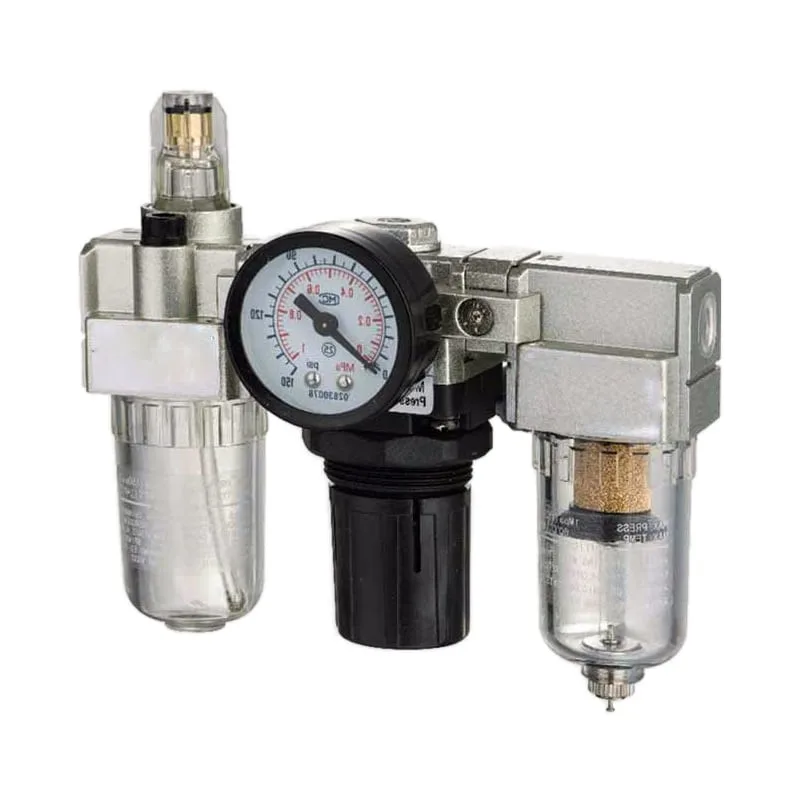
No single air-treatment component removes every form of water. Festo describes filter-regulator units as devices that separate contaminants and liquid water while controlling downstream pressure (Festo Air Preparation, 2024). Vapor removal and a specified low pressure dew point require a suitable dryer, not merely a finer local filter.
| Treatment stage | Primary moisture function | What it cannot prove by itself |
|---|---|---|
| Aftercooler | cools compressed air so bulk vapor condenses | that all liquid has been drained |
| Water separator | removes entrained bulk liquid | a low pressure dew point |
| Receiver and automatic drain | collects and discharges condensate | dryer performance at peak flow |
| Refrigerated dryer | lowers water-vapor content for many above-freezing installations | suitability for every cold or critical process |
| Desiccant dryer | achieves lower pressure dew points when correctly selected and maintained | dry air if prefilters, drains, regeneration, or desiccant are compromised |
| Particulate or coalescing filter | removes specified particles or aerosols and captured liquid | removal of water vapor to a defined dew point |
| Local filter-regulator | final liquid/particle separation and pressure control | correction of a wet distribution network |
Parker recommends condensate drains at locations such as aftercoolers, receivers, filters, dryers, and distribution low points (Parker Condensate Drain Guide, 2019). A drain must be installed, valved, sized, and maintained so it actually discharges. A closed isolation valve can make a healthy drain appear defective; an open bypass can waste air or defeat treatment.
Dryer selection must be corrected for maximum inlet temperature, minimum inlet pressure, peak flow, ambient conditions, and required outlet dew point. When an alarm appears only during a production surge, compare those actual conditions with the manufacturer’s rating rather than assuming the dryer nameplate flow is available under every condition.
Lubrication is a separate decision. Do not add an airline lubricator as a water-control measure. Follow the valve and cylinder manufacturers’ lubrication instructions, because introducing oil into a system designed for non-lubricated service can create compatibility and maintenance problems.
A Cylinder-Specific Prevention Plan
A reliable prevention plan controls water from the compressor room to the actuator boundary. Parker’s dryer troubleshooting guidance lists high flow, high inlet temperature, drain faults, bypass leakage, filter condition, aftercooler performance, and desiccant condition among relevant checks (Parker Dryer Manual, 2018). The plan should assign each check to a measurable acceptance criterion.
- Define the requirement. Record the required pressure dew point, acceptance location, line pressure, peak flow, and coldest expected temperature. Add the relevant ISO 8573-1 class only after the application requirement is known.
- Remove bulk condensate early. Verify the aftercooler, separator, receiver, and automatic drains under real operating conditions. Route condensate for compliant treatment and disposal.
- Select and verify the dryer. Apply the manufacturer’s correction factors. Confirm performance at peak demand and after seasonal temperature changes.
- Protect the distribution network. Avoid unintended low points, use appropriately arranged drops and drip legs, and drain known collection points. After a major moisture event, inspect the downstream network for retained liquid and rust.
- Check the point of use. Measure pressure dew point and dynamic pressure near the valve manifold or actuator, not only at the compressor room.
- Maintain local preparation. Inspect bowls, elements, differential-pressure indicators, and drains according to condition, manufacturer guidance, and risk. A calendar alone cannot reveal an overloaded element or blocked drain.
- Protect the actuator externally. Use the correct enclosure, guarding, scraper arrangement, corrosion-resistant materials, fittings, and mounting orientation for washdown, coolant, outdoor, or condensing service.
- Control shutdown and restart. Drain designated low points, investigate alarms, and verify the branch before restarting a moisture-sensitive machine.
Avoid publishing one universal filter-change or drain-check interval. Duty, inlet quality, environment, and consequence of failure vary too widely. Base the interval on differential pressure, drain operation, dew-point trend, inspection findings, manufacturer instructions, and documented risk.
[UNIQUE INSIGHT] A compliant dryer outlet does not close the investigation. Old branch piping can store liquid, a receiver can reintroduce condensate, and a local low point can remain wet. Acceptance at the machine inlet is what connects central air treatment to cylinder reliability.
If moisture occurs mainly in cold areas, use the separate cold-weather pneumatic failure guide. If rust particles are already reaching small passages, the control-valve contamination guide covers the downstream valve risks.
Repair and Replacement Boundaries
Repair or replacement should follow a safe inspection and the manufacturer’s limits, not a generic rule based on visible rust alone. Condensed water can create corrosion, but the critical decision depends on pitting depth, sealing-surface condition, dimensional tolerance, bearing or guide damage, cushion function, available repair parts, and whether the original ingress path has been corrected.
Before disassembly, isolate electrical and pneumatic energy, exhaust trapped pressure through the designed safe path, secure gravity or stored mechanical loads, and follow the site’s lockout procedure. Some actuator chambers, accumulators, or vertical loads can retain hazardous energy even after the main supply is closed.
Consider an authorized repair only when the manufacturer permits rebuilding and the inspected pressure-containing, guiding, and sealing surfaces remain within specification. Replace the actuator or affected structural parts when corrosion, scoring, deformation, cracked components, damaged threads, or unavailable tolerances make a safe repair uncertain.
Do not sand, plate, hone, or substitute seals without an approved repair specification. Removing corrosion can change clearances and surface finish. Seal material also cannot be selected from a simple “water resistance” ranking: temperature, lubricant, cleaning chemical, pressure, speed, and manufacturer approval all matter.
Most importantly, correct the upstream or external ingress path before returning the machine to service. A new cylinder connected to the same wet branch or exposed to the same spray path is a replaced symptom, not a closed corrective action.
What Data Belongs in a Moisture-Damage RFQ?
A useful replacement or troubleshooting request identifies the cylinder and documents the conditions that damaged it. Dryer selection guidance depends on flow, pressure, temperature, and required dew point, while cylinder selection also depends on load, stroke, speed, mounting, and environment. Missing those variables encourages a dimensional match that repeats the original failure.
Include:
- manufacturer, complete model number, bore, stroke, port size, and mounting style;
- rodless or rod-type construction, guide arrangement, sensors, and cushion options;
- working pressure, dynamic pressure at the machine, cycle profile, speed, load, and side load;
- compressed-air purity requirement and measured pressure dew point at a named location;
- normal and peak flow, dryer model, filter grades, drain arrangement, and recent alarms;
- lowest ambient temperature and any washdown, coolant, rain, salt, chemical, or condensation exposure;
- photographs of the installed orientation, tubing route, filter bowls, drains, ports, rod or sealing band, and internal damage;
- teardown findings, maintenance records, failure timing, and whether other components on the branch are affected;
- applicable safety, food-contact, cleanroom, corrosion, or customer specifications.
Do not describe the problem only as “waterproof cylinder required.” State whether the evidence points to internal supply moisture, external ingress, or both. That distinction changes the air-treatment scope, cylinder materials, sealing interfaces, guarding, and validation plan.
For a technical review, send the model number, operating conditions, air-quality data, application photos, and teardown evidence through the technical contact page.
Pneumatic Cylinder Water-Damage FAQs
Water-damage questions are best answered by separating vapor, liquid condensate, particles, and external exposure. ISO 8573-1 treats water as an independent compressed-air contaminant category, while equipment manufacturers define the environmental and air-quality limits for their own products. The following answers are diagnostic starting points, not substitutes for model-specific instructions.
Can a standard pneumatic filter remove all water before it reaches the cylinder?
No. A standard filter or separator can remove captured liquid droplets and specified particles, but it does not by itself lower water vapor to a defined pressure dew point. Use properly selected bulk-liquid separation, drains, and a dryer, then verify the dew point at the machine inlet.
Why is the dryer outlet dry while the cylinder still contains water?
Water may remain in a receiver or legacy branch, collect in a low point, pass a failed downstream drain, or enter the cylinder externally. Test pressure dew point and inspect condensate at multiple points from the dryer outlet to the machine while the system runs at representative flow.
Is visible rust enough reason to replace the whole cylinder?
Not always. The decision depends on the location and severity of corrosion, pitting, sealing-surface condition, dimensional tolerance, guide or bearing damage, cushion function, and the manufacturer’s repair limits. Isolate the machine, preserve evidence, and inspect before cleaning or ordering parts.
Will a stainless-steel or corrosion-resistant cylinder solve wet-air failures?
It may reduce some external-corrosion risks, but it does not correct wet compressed air, failed drains, or inadequate drying. Material selection and ingress protection must match the environment, while the air system still needs a verified pressure dew point and functioning condensate-removal chain.
Where should pressure dew point be measured for cylinder protection?
Measure it at the point where the air-quality requirement applies, usually near the machine inlet or valve manifold, at the relevant line pressure and operating flow. Compare that value with the coldest downstream surface. Dryer-outlet measurements are also useful, but they do not prove the branch remains dry.
Where Do the Technical Limits Come From?
The limits and troubleshooting boundaries in this guide come from published standards and manufacturer engineering documents. ISO defines the purity-class framework; CAGI reproduces the water-class limits; Parker and Festo explain condensation, treatment stages, drain locations, dryer selection, and fault checks. Together, these sources separate documented engineering limits from application-specific decisions.
- ISO 8573-1:2010, Compressed air, Part 1: Contaminants and purity classes. Official standard page. Retrieved 2026-07-18.
- CAGI Compressed Air Purity Guide. ISO 8573-1 water-class reference table. Retrieved 2026-07-18.
- Parker Drying Compressed Air Guide. Condensation mechanism and dryer fundamentals. Retrieved 2026-07-18.
- Parker Condensate Drain Guide. Recommended drain locations and condensate-management principles. Retrieved 2026-07-18.
- Parker DME Dryer Operating Manual. Dryer selection inputs and dew-point troubleshooting checks. Retrieved 2026-07-18.
- Festo: How does an air preparation unit work?. Filter-regulator operation and liquid separation. Retrieved 2026-07-18.
- YouTube: Air Quality Classes ISO 8573-1. Visual supplement for the standard’s particle, water, and oil classes. Retrieved 2026-07-18.