

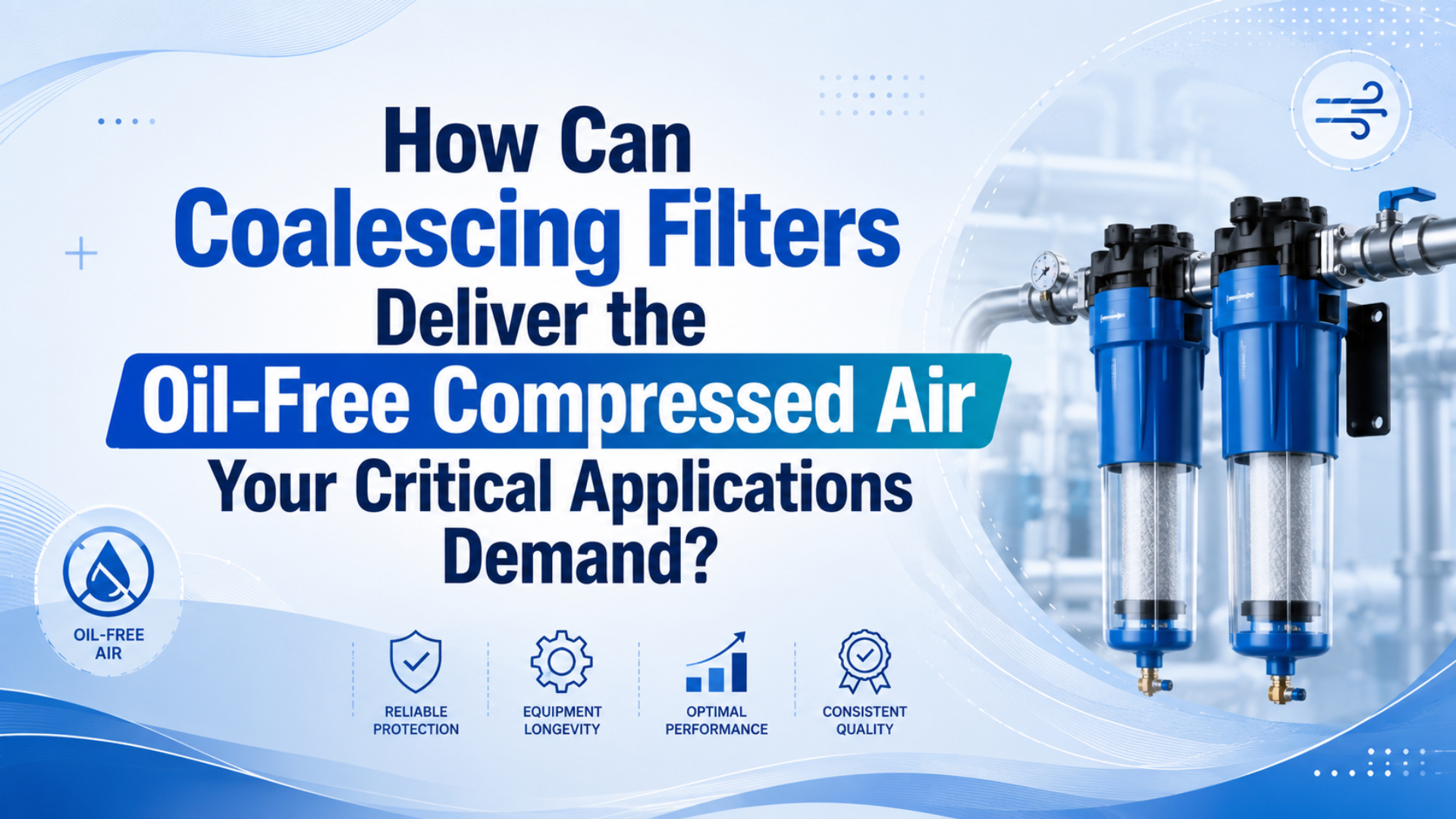
A coalescing filter can help deliver very low-oil compressed air, but it cannot make every system oil-free by itself. It removes liquid oil aerosol, entrained water droplets, and fine solids. It does not remove water vapor, and it may need an adsorption stage to control oil vapor.
For a critical process, the defensible approach is to define the required ISO 8573-1 particle:water:oil classes, select a complete treatment train, and verify the result at the point where the air enters the machine or product-contact process. A filter’s catalog rating is useful evidence. It isn’t an acceptance test for the installed system.
Key Takeaways
- Parker rates one high-efficiency coalescing grade at 0.01 mg/m3 remaining oil under stated test conditions.
- Oil aerosol, oil vapor, and water vapor require different treatment and test methods.
- Specify the measurement point, peak flow, pressure drop, and acceptance limit before selecting a filter.
How Can a Coalescing Filter Support Oil-Free Compressed Air?
Parker rates its OIL-X Grade AA coalescing stage for 0.01 mg/m3 maximum remaining oil at 21 degrees C and 99.9999% filtration efficiency under stated test conditions (Parker OIL-X, accessed 2026). That is strong product-level performance, not proof that every installed system will deliver the same air quality.
Coalescing media works by making small liquid droplets collide with fibers, merge into larger droplets, and move to the drainage layer. The bowl and drain then remove the collected liquid. This process is well suited to oil aerosol and liquid water carried in the air stream.
Oil aerosol is a suspension of fine liquid oil droplets in the compressed-air stream. It differs from oil vapor, which remains in the gas phase. That distinction determines whether coalescing media can capture the contaminant or whether the system needs adsorption and a separate vapor test.
Three conditions decide whether the catalog result can be reproduced in a plant:
- The inlet contaminant must be within the element’s tested challenge range.
- Air flow, pressure, and temperature must remain within the rated conditions.
- The drain and downstream treatment must prevent collected liquid or vapor from reaching the process.
A nominal particle rating such as 0.01 micron does not describe the entire air-quality result. It doesn’t state the water pressure dew point. It doesn’t prove oil-vapor removal. It also doesn’t reveal the pressure loss at peak flow. For the underlying filtration mechanism and general grade selection, use the separate coalescing filter guide. This article focuses on critical-process verification.
Why Doesn’t an Oil-Free Compressor Set the Point-of-Use Air Class?
ISO 8573-1 defines 3 separate compressed-air purity groups, particles, water, and oil, and applies them independently of where air is specified or measured in the system (ISO 8573-1, 2010). An oil-free compressor describes the compression technology. The process still needs a measured particle:water:oil result at its acceptance point.
This distinction prevents two common specification errors. First, an oil-free compressor does not control rust, pipe scale, condensate, hose debris, or contamination introduced during maintenance. Second, a coalescing filter installed after an oil-lubricated compressor does not convert the compressor itself into an oil-free design.
Ambient air and distribution piping also matter. CAGI notes that atmospheric air can contain oil vapor and that an oil-free compressor alone does not guarantee oil-free air at every downstream location (CAGI Resource Library, accessed 2026). The exact inlet load is site-specific, so a universal inlet-oil range isn’t defensible without measurement.
Write the requirement at the place where the risk exists:
Compressed air at the process inlet:
ISO 8573-1 particles:water:oil = [P]:[W]:[O]
Normal flow: ___
Peak flow: ___
Operating pressure: ___
Measurement point: after final treatment, before the process connection
In our experience, the most useful air-quality notes identify both the class and the physical sampling point. A class written only on the compressor-room drawing leaves maintenance and quality teams guessing whether it applies before the dryer, after the main filter, at the machine inlet, or at the process connection.
The related ISO air-quality guide explains how to write the three class numbers. If water is the limiting contaminant, review pressure dew point before selecting another filter.
Which Contaminants Can Coalescing Media Remove?
ISO 8573-2:2018 covers liquid oil and oil aerosols but excludes oil vapor, while ISO 8573-5:2025 provides the separate gas-chromatography method for oil vapor (ISO 8573-2, 2018; ISO 8573-5, 2025). Those 2 standards show why one coalescing element cannot be credited with every form of oil removal.
Oil vapor is oil contamination present in the gas phase rather than as suspended liquid droplets. Cooling may change how much vapor condenses, but a coalescing filter should not be credited with vapor control unless the complete system has been tested for that fraction.
| Contaminant | Coalescing filter role | Additional control that may be required |
|---|---|---|
| Liquid oil aerosol | Primary duty; droplets collect, merge, and drain. | Upstream bulk separation if the inlet load is high. |
| Liquid water droplets | Captures entrained droplets. | Separator and reliable automatic drainage for bulk liquid. |
| Fine solids | Some solids are captured, but heavy loading raises restriction. | Particulate prefilter for rust, scale, and installation debris. |
| Oil vapor | Not the same as liquid aerosol. | Activated carbon or another validated adsorption stage. |
| Water vapor | Not removed by ordinary filtration. | Refrigerated, membrane, or desiccant dryer selected by dew point. |
The useful design boundary is contaminant state, not the word “oil.” A laboratory report for oil aerosol does not automatically prove total oil performance when vapor is present. Likewise, a dry line can still carry oil aerosol, while a low-oil line can still fail its water class. Each risk needs the right treatment and measurement method.
This boundary also improves troubleshooting. Wet filter bowls point toward condensate and drain loading. Oil odor downstream of a functioning coalescing stage may indicate vapor or saturated adsorption media. Rust inside a pneumatic control valve points back toward water and distribution piping, not necessarily filter efficiency.
What Treatment Train Does a Critical Application Need?
Parker specifies that its 0.01 mg/m3 Grade AA coalescing stage should be preceded by Grade AO, while its 0.003 mg/m3 oil-vapor reduction stage is preceded by AO plus AA (Parker OIL-X, accessed 2026). The exact grade names are vendor-specific, but the staged-treatment principle is broadly useful.
A critical-process treatment train commonly includes:
- Aftercooling and a receiver to cool air and collect condensate.
- A bulk liquid separator and dependable drain.
- A dryer selected for the required pressure dew point.
- A particulate prefilter when rust or scale could load the fine media.
- A coalescing filter for liquid oil aerosol and fine droplets.
- An adsorption or activated-carbon stage when oil vapor is part of the limit.
- A final sterile or particulate stage only when the process specification requires it.
- A sampling point after final treatment and before the critical process.
Think of the train as a set of control layers. The dryer controls water vapor. The coalescing stage controls liquid aerosol. Adsorption controls vapor. The final test confirms their combined result. Buying the finest element available doesn’t repair a missing dryer, a flooded separator, an oil-saturated carbon bed, or dirty downstream piping.
Treatment order also depends on the equipment supplier. Some dryers require upstream oil-aerosol protection; others specify filtration after the dryer. Temperature affects both condensation and adsorption, so the final arrangement must follow the dryer and filter manuals rather than a universal diagram.
At machine level, a filter regulator can protect local valves and actuators, but it shouldn’t be asked to replace the compressor-room separator, dryer, and main filtration system. The FRL sizing guide explains how local treatment capacity affects flow and pressure.
How Should You Specify and Size a Coalescing Filter?
ISO 12500-1 requires coalescing-filter performance to include outlet oil-aerosol concentration in mg/m3 and pressure-drop characteristics under standard rating parameters (ISO 12500-1, 2007). Parker publishes its stated flows at 7 bar(g), 20 degrees C, 1 bar(a) reference pressure, and 0% relative water-vapor pressure, showing why port size alone cannot select a filter.
Start with the required result, then collect the operating data:
| RFQ input | Why it changes the decision |
|---|---|
| Required ISO particle:water:oil classes | Defines what must be controlled and measured. |
| Normal and peak flow | Prevents an element from being sized only for average demand. |
| Minimum process pressure | Sets the available pressure-drop budget. |
| Operating and inlet temperature | Affects condensation, vapor loading, and adsorption. |
| Compressor type and expected oil load | Helps determine prefiltration and treatment stages. |
| Dryer type and pressure dew point | Separates moisture control from oil-aerosol control. |
| Clean and saturated differential pressure | Shows restriction at the start of service. |
| Drain type and condensate handling | Prevents collected liquid from returning downstream. |
| Test method and sampling point | Makes the final acceptance result reproducible. |
Compare flow at the actual working pressure, not just the catalog’s headline capacity. Parker’s own data shows that saturated differential pressure changes with percentage of rated flow. A filter can therefore meet its oil-aerosol rating yet still be unsuitable because it consumes too much of the machine’s pressure margin.
In our experience, an RFQ that lists only port size usually produces avoidable follow-up. Peak flow, working pressure, inlet temperature, required oil result, dryer arrangement, drain type, and available pressure-drop budget are the inputs that separate a workable filter selection from a housing that merely fits the pipe.
CAGI recommends no more than 10% total pressure drop between compressor discharge and point of use, and estimates that every 2 psig of excess operating pressure raises compressor power by about 1% (CAGI, accessed 2026). That is a system guardrail, not an allowable drop for one filter.
The Bepto compressed-air pressure-drop calculator can estimate losses through connected tubing and piping. It cannot replace the filter manufacturer’s tested differential-pressure curve, so it is intentionally provided as a normal link rather than a calculator card.
How Do Critical Applications Set the Acceptance Limit?
U.S. food regulation 21 CFR 117.40 requires compressed air introduced into food or used on food-contact surfaces to be treated so it doesn’t contaminate food, but it specifies 0 universal oil-concentration limits (eCFR, accessed 2026). The process owner must translate product risk and applicable standards into a written acceptance value.
For example, a product-contact air nozzle needs an acceptance plan that names the product risk, oil fraction, particle limit, water requirement, microbiological requirement if applicable, production condition, sampling location, laboratory method, detection limit, and corrective action. The adjacent actuator branch may have a less demanding target because its air never contacts the product. Treating both branches identically can waste pressure and replacement elements, while testing only the easier actuator branch can miss the actual product risk. The regulation supplies the contamination-control obligation, but the plant’s validated process must supply the measurable limits. This is why a generic statement such as “food air requires 0.01 ppm oil” should never replace a documented hazard review and point-of-use acceptance procedure (21 CFR 117.40, accessed 2026).
Food, pharmaceutical, electronics, painting, and medical-device operations may all need tighter air quality than general factory motion. They do not automatically share one oil limit. The correct requirement can come from a product standard, validated process, customer specification, equipment supplier, risk assessment, or regulatory interpretation.
Use this acceptance sequence:
- Identify whether compressed air contacts the product, product-contact surface, instrument, or only an actuator.
- List the harmful contaminants and their physical states.
- Assign a limit and test method to each contaminant.
- Name the sampling point and production condition.
- Define pass/fail action, retest rules, and change-control requirements.
The same machine can need two air specifications. Product-contact blow-off may require documented oil, particle, water, and microbiological limits. A guarding cylinder on that machine may only need reliable general-purpose air. Separating those branches can reduce treatment cost while keeping the critical process measurable.
Avoid replacing risk assessment with industry-wide claims such as “all pharmaceutical air must be 0.01 ppm” or “every electronics line needs Class 1.” Even Class 0 isn’t a universal zero. It is a user- or supplier-defined limit more stringent than Class 1 for the specified contaminant, with its own test and acceptance conditions.
How Should You Verify Oil Content at the Point of Use?
ISO 8573-2 describes 2 main approaches for oil-aerosol analysis: Method A collects oil with inline coalescing filters, while Method B uses sampling discs followed by solvent extraction and instrumental analysis (ISO 8573-2, 2018). Oil vapor is tested separately under ISO 8573-5, so the sampling plan must state which fraction is being measured.
Place the final acceptance point after the last treatment stage and before the process connection. Also consider upstream diagnostic points at the compressor outlet, dryer outlet, main header, and machine inlet. Results from these locations answer different questions; they shouldn’t be treated as interchangeable certificates.
Point-of-use air quality means the measured condition at the location where the process, machine, or component receives the compressed air. A compressor-outlet certificate can support diagnosis, but it cannot prove the condition after dryers, filters, storage, old piping, hoses, and local regulators.
Before sampling, document:
- production state and air demand;
- system pressure and air temperature;
- recent filter or dryer service;
- sampling-line material and cleanliness;
- stabilization or purge time required by the test method;
- whether the result covers aerosol, vapor, liquid oil, or total oil;
- laboratory method, detection limit, uncertainty, and report units.
Why test during representative production? A clean result at idle may miss flow-dependent pressure loss, drain overload, contamination released by cycling equipment, or a branch that is used only during peak demand. The acceptance condition should resemble the process condition that creates the risk.
In our experience, upstream and downstream samples are most valuable when they answer one written diagnostic question. Sampling everywhere without a hypothesis adds cost but may not identify whether the source is the compressor, dryer, filter train, distribution header, local branch, or process hose.
If the result fails, don’t immediately add another fine filter. Compare upstream and downstream samples, inspect drains, confirm dryer performance, check for old lubricated branches, and verify that the adsorption stage hasn’t saturated. That sequence locates the source instead of masking it.
What Maintenance Keeps Coalescing Performance Defensible?
Parker specifies a 12-month element change for its AO and AA grades, while Donaldson’s DF system uses a differential-pressure indicator to identify an appropriate replacement interval (Parker OIL-X; Donaldson DF, accessed 2026). Those 2 approaches show why a universal quarterly or 2,000-hour rule is unreliable.
Use the manufacturer’s interval as the upper boundary, then adjust maintenance to application risk and measured condition. Differential pressure is valuable, but it is a restriction indicator, not a direct air-quality measurement. A torn or bypassed element can show low pressure drop while passing contamination.
Record these items for each filter stage:
| Maintenance record | Decision it supports |
|---|---|
| New-element differential pressure | Establishes a baseline at normal and peak flow. |
| Current differential pressure | Identifies loading and lost pressure margin. |
| Drain operation and bowl condition | Shows whether captured liquid is leaving the housing. |
| Element installation date and hours | Supports scheduled replacement. |
| Upstream dryer and separator condition | Reveals overload sources. |
| Downstream oil and dew-point results | Confirms whether the treatment train still meets its target. |
CAGI also warns that compressed-air filters cannot reduce moisture vapor or pressure dew point (CAGI Resource Library, accessed 2026). If a bowl repeatedly fills with water, inspect the separator, dryer, drains, and pipe temperature. Shortening the coalescing-element interval alone won’t correct the moisture source.
After an element change, depressurize and isolate the housing according to its manual, inspect seals and bowl condition, install the correct element and flow direction, restore pressure gradually, and record the new baseline. Critical processes may require a downstream quality test before production is released.
Build the Specification Around Verification, Not the Word Oil-Free
ISO 8573-1 separates compressed-air purity into 3 contaminant groups, while ISO 8573-2 and ISO 8573-5 use different methods for aerosol and vapor (ISO 8573-1, 2010; ISO 8573-2, 2018; ISO 8573-5, 2025). A reliable critical-air specification must therefore define the contaminant, limit, treatment stage, measurement point, and test method.
A coalescing filter is excellent at the job it was designed to do: remove liquid aerosols and drain them from the air stream. It becomes misleading only when its micron rating or vendor outlet value is used as proof of water-vapor control, oil-vapor removal, or point-of-use compliance.
Start with the process risk. Then specify the particle:water:oil target, normal and peak demand, pressure-drop budget, treatment stages, sampling location, and maintenance evidence. That approach produces an air-quality result that engineering, quality, maintenance, and suppliers can all verify.
FAQ About Coalescing Filters and Oil-Free Compressed Air
Parker’s 0.01 mg/m3 Grade AA rating, ISO 8573-1’s 3 contaminant groups, and the separate ISO 8573-2 and ISO 8573-5 test methods answer most recurring questions (Parker OIL-X; ISO, accessed 2026). The key is to distinguish a filter rating from the measured performance of the complete installed system.
Can a coalescing filter remove oil vapor?
No. A coalescing filter is designed mainly for liquid oil aerosol and entrained droplets. ISO 8573-2:2018 explicitly excludes oil-vapor testing, while ISO 8573-5:2025 covers vapor by pressurized sampling and gas chromatography. If vapor is included in the oil limit, use a validated adsorption stage and test both fractions.
Is a 0.01-micron filter automatically ISO 8573-1 Class 1?
No. A 0.01-micron product rating doesn’t establish the complete particle, water, and oil classes. ISO 8573-1 treats those as 3 separate groups. Confirm particle-count performance, pressure dew point, total-oil requirement, test method, and sampling point instead of translating one media rating into an entire air-quality class.
Do oil-free compressors still need coalescing filters?
It depends on the installed system and process limit. Oil-free compression does not remove downstream rust, condensate, hose debris, or contamination left in old piping. Define the 3 ISO 8573-1 contaminant classes and test at the point of use. Add coalescing filtration only when liquid aerosol or droplet control is required.
How often should a coalescing element be replaced?
Follow the filter manufacturer’s interval and condition limits. Parker lists 12 months for specific OIL-X AO and AA elements, while Donaldson offers differential-pressure-based replacement support. Don’t apply either value to an unrelated housing. Track installation date, differential pressure, drain condition, inlet loading, and downstream quality results together.
Where should compressed-air oil content be measured?
Measure at the point where the air-quality promise applies, normally after final treatment and before the critical process connection. ISO 8573-1 says purity classes apply independently of system location. Additional samples at the compressor, dryer, header, or machine inlet can isolate the source, but they don’t replace final point-of-use acceptance.
Sources
The evidence base uses 4 ISO standard pages, 1 U.S. regulation, and 4 primary industry resources. ISO 12500-1 remains the central performance reference because it covers both outlet oil-aerosol concentration and pressure drop for coalescing-filter testing (ISO 12500-1, 2007). Product values remain tied to their manufacturers and stated test conditions.
- ISO 8573-1:2010, Compressed air purity classes, accessed 2026-07-14.
- ISO 8573-2:2018, Oil aerosol content measurement, accessed 2026-07-14.
- ISO 8573-5:2025, Oil vapor content measurement, accessed 2026-07-14.
- ISO 12500-1:2007, Coalescing filter oil-aerosol test methods, accessed 2026-07-14.
- 21 CFR 117.40, Equipment and utensils, accessed 2026-07-14.
- Parker OIL-X Compressed Air Filters, product performance and test conditions, accessed 2026-07-14.
- Donaldson DF Series Compressed Air Filter Housings, differential-pressure monitoring, accessed 2026-07-14.
- CAGI Resource Library, air-treatment boundaries and maintenance guidance, accessed 2026-07-14.
- CAGI Working With Compressed Air, pressure-drop and energy guidance, accessed 2026-07-14.
- Trace Analytics, Compressed Air & Gas Quality: Why It’s Important, video, accessed 2026-07-14.