

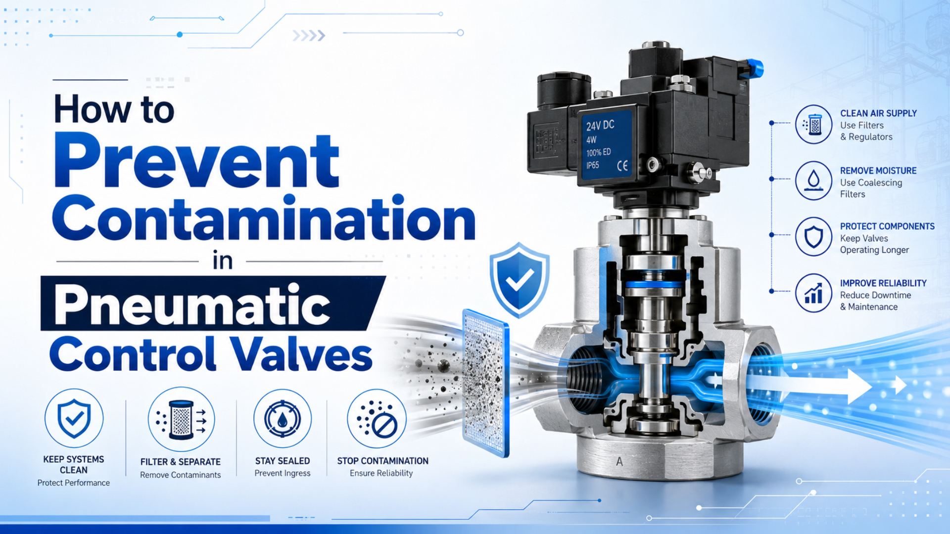
Prevent contamination in pneumatic control valves by defining the required air purity at the valve inlet, removing bulk liquid before fine filtration, selecting a dryer for the required pressure dew point, controlling pipe-generated debris, and verifying the result at representative sampling points. A filter alone cannot remove every contaminant.
Particles, liquid water, water vapor, oil aerosol, oil vapor, rust, pipe scale, seal debris, thread compound, and maintenance dirt behave differently. Each needs the right control method. The practical goal isn’t “clean air” as a vague promise. It is a measured particle, water, and oil condition that matches the valve manufacturer’s specification and the machine environment.
Key Takeaways
- ISO 8573-1 uses three independent classes for particles, water, and oil; Class 1.4.1 does not mean a −40°C pressure dew point.
- Parker and SMC both publish 5 μm filtration guidance for specific directional-valve families.
- Filters remove particles or aerosols, while dryers reduce water vapor and pressure dew point.
- Sample at the point of use and inspect failed valves before changing the treatment train.
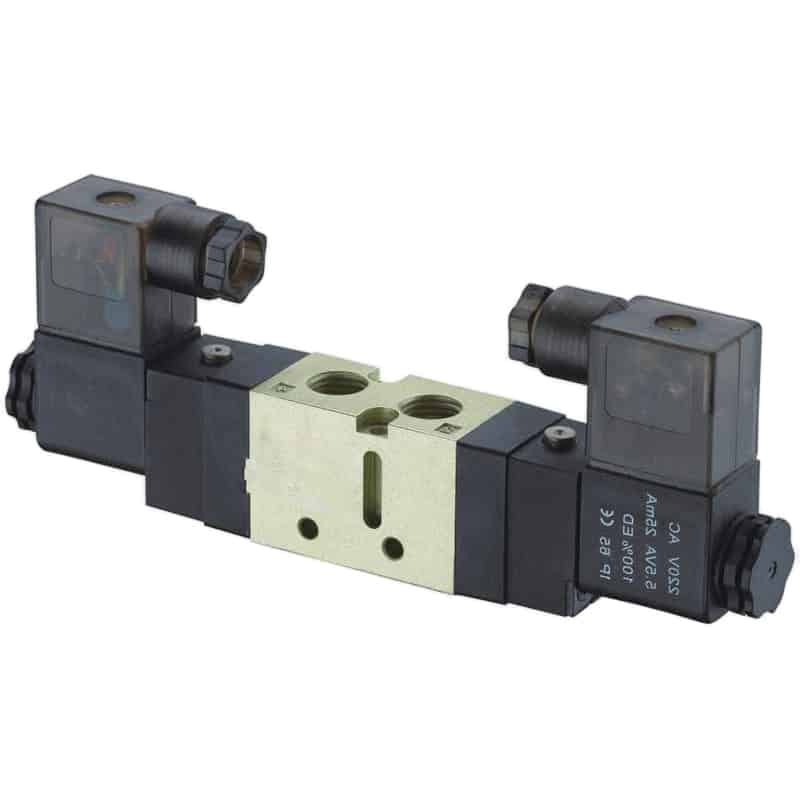
Small pilot passages, sliding seals, seats, and exhaust paths can all be affected by particles, condensate, oil residue, or installation debris.
Where does pneumatic valve contamination come from?
CAGI lists 10 common compressed-air contaminants: water vapor, liquid water, water aerosols, liquid oil, oil vapor, oil aerosols, rust, pipe scale, atmospheric dirt, and microorganisms (CAGI Resource Library, accessed 2026). Preventing valve problems begins by locating which source can create the residue found at the point of use.
Supply-side contamination enters with ambient air or is added during compression and treatment. Compressor intake air can contain dust, pollen, hydrocarbon vapor, moisture, and microorganisms. An oil-injected compressor can add oil aerosol, vapor, and wear debris. An oil-free compression chamber reduces one source, but it doesn’t remove contaminants already present in ambient air or downstream piping.
Water contamination changes form as pressure and temperature change. The aftercooler condenses much of the water vapor carried through the compressor, creating liquid water and aerosol that need separation and drainage. Any vapor left can condense farther downstream if the pipe temperature falls below the pressure dew point. See the pressure-dew-point guide for the temperature relationship.
Distribution-system contamination develops after the compressor room. Corroding steel pipe releases rust and scale. Old receiver tanks, dead legs, poorly drained low points, saturated desiccant, degraded hoses, and seal fragments can add material that an upstream filter cannot intercept if it is generated downstream of that filter.
Maintenance contamination is often local. Cut tubing, metal chips, excess thread sealant, dirty replacement parts, open manifolds, contaminated tools, and flushed debris can enter a valve during installation. A spotless compressor room doesn’t protect a valve assembled on a dirty bench.
The residue’s location is evidence. Contamination found upstream and downstream of a point-of-use filter suggests breakthrough, bypass, wrong installation, or a saturated element. Clean inlet air with debris inside one manifold points instead toward local assembly, wear, exhaust ingestion, or material compatibility.
How should ISO 8573-1 air-purity classes be applied?
ISO 8573-1:2010 defines three separate purity classifications for particles, water, and oil, independent of where the air is specified or measured (ISO, accessed 2026). Write the class as [particles:water:oil], then state the measurement location and operating condition; don’t assign one “precision valve” class to every product.
The first number covers solid particles. The second covers water, usually by pressure dew point for the relevant classes. The third covers total oil, including aerosol, liquid, and vapor as defined by the standard. A dash means that contaminant hasn’t been specified. Class 0 is not zero contamination; it is a user- or supplier-defined requirement stricter than Class 1.
CAGI’s reproduced ISO table shows why each digit must be read separately (CAGI Compressed Air Purity Guide, 2026):
| Example class | What the digit means |
|---|---|
| Particle Class 1 | Up to 20,000 particles/m³ at 0.1–0.5 μm, 400 at 0.5–1.0 μm, and 10 at 1.0–5.0 μm |
| Water Class 2 | Pressure dew point at or below −40°C |
| Water Class 4 | Pressure dew point at or below +3°C |
| Oil Class 1 | Total oil at or below 0.01 mg/m³ |
Therefore [1:4:1] combines Particle Class 1, Water Class 4, and Oil Class 1. It does not specify “particles smaller than 0.1 μm,” and its water digit does not mean −40°C. The site’s ISO compressed-air quality guide explains the class table in more detail.
Select the target in this order:
- Obtain the valve or manifold’s required inlet-air specification.
- Add process requirements, such as low-temperature operation, paint compatibility, food contact, or analytical instrumentation.
- Identify the point where the class must be achieved.
- Choose treatment equipment capable of meeting all three digits at peak flow and worst inlet conditions.
- Define the ISO 8573 test method and sampling plan used for acceptance.
What if the valve manual only says “filtered compressed air”? Ask the supplier for filtration grade, water limit, oil compatibility, lubrication policy, and test basis. A filter micron label alone does not define an ISO 8573 class.
Treatment stages for particles, water, and oil
CAGI separates at least four treatment jobs: mechanical separation, particulate filtration, coalescing filtration, and adsorption, while air dryers remove water vapor (CAGI Treatment Handbook, 2017). Correct sequencing prevents a fine filter or dryer from receiving bulk liquid and contamination it was not designed to handle.
A typical plant-air path may include:
compressor intake filter
→ compressor
→ aftercooler
→ moisture separator and drain
→ prefilter or coalescing filter as required
→ dryer
→ afterfilter where required
→ receiver and distribution
→ point-of-use filter/regulator
→ control valve
The exact order depends on dryer type and manufacturer instructions. A desiccant dryer commonly needs upstream protection from liquid water and oil aerosol, plus downstream particulate filtration for desiccant dust. A refrigerated dryer and a membrane dryer have different inlet requirements. Follow the selected equipment’s published arrangement.
| Treatment component | Primary job | What it does not replace |
|---|---|---|
| Aftercooler | Lowers air temperature so vapor can condense | Separator, drain, dryer, or filter |
| Moisture separator | Removes bulk entrained liquid | Removal of water vapor |
| Particulate filter | Captures rated solid particles | Dryer or oil-vapor adsorption |
| Coalescing filter | Collects fine liquid water and oil aerosols into drainable drops | Removal of water vapor or all oil vapor |
| Compressed-air dryer | Reduces water vapor and pressure dew point | Particle and oil control unless specifically integrated |
| Activated-carbon adsorber | Reduces oil vapor and odor under specified conditions | Bulk-liquid or particulate protection |
| Point-of-use FRL | Local filtration, pressure regulation, and optional lubrication | Central drying and upstream condensate control |
CAGI notes that particulate and coalescing filters may remove very small solid or liquid particles, but activated carbon is used for vapor adsorption and should be protected from gross liquid oil. The site’s coalescing-filter guide explains the aerosol mechanism. One “0.01 μm filter” label cannot prove control of particles, water vapor, oil aerosol, and oil vapor simultaneously.
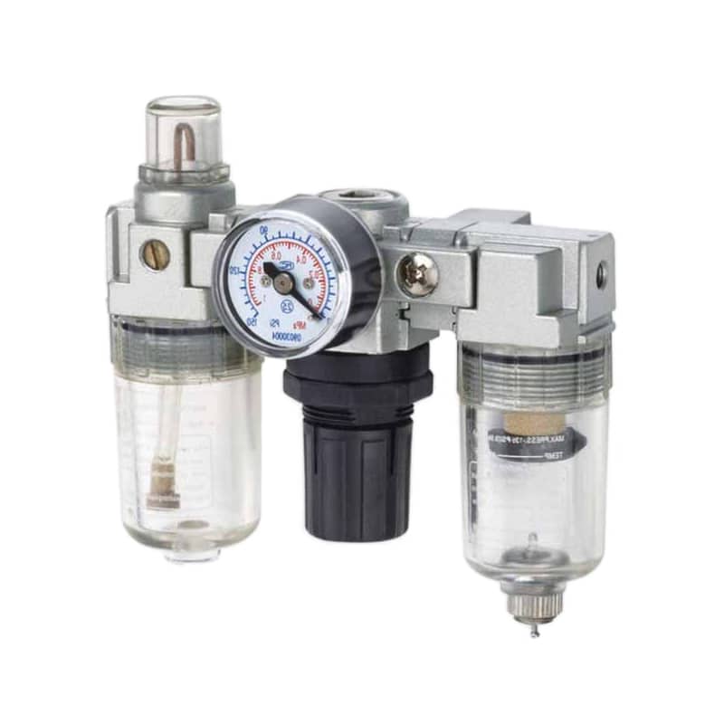
An FRL can protect a local valve station, but the filter bowl cannot reduce pressure dew point and the lubricator should only be used when downstream components permit or require lubrication.
What filtration should be installed close to the valve?
SMC’s SY-series manual specifies an upstream filter close to the valve with filtration of 5 μm or finer, and Parker likewise recommends a 5 μm filter near its Isys ISO valve (SMC SY manual; Parker Isys service instructions, accessed 2026). These are product-family requirements, not an automatic rule for every pneumatic valve.
Place the final filter upstream of the protected valve group and downstream of piping that may shed debris. Keep enough clearance to inspect the bowl, drain condensate, read a differential indicator, and replace the element without opening dirty pipe over the manifold. Follow the permitted mounting orientation and bowl-material limits.
Finer isn’t always better. A fine element collects more material and can create excessive pressure drop if it is undersized or used without a coarse upstream stage. Festo describes 40 μm and 5 μm standard filtration and recommends staged filtration when higher purity is needed, rather than loading the finest element with every large particle (Festo, accessed 2026).
Size the filter using the manufacturer’s corrected-flow data at the actual:
- inlet pressure
- peak and average flow
- ambient and air temperature
- required filtration grade
- permitted clean and loaded pressure drop
- bowl and drain type
- condensate chemistry
Do not apply an unsupported 125–150% multiplier. Use the supplier’s sizing method and leave a documented pressure-drop margin for element loading. If multiple valves exhaust and refill large cylinders simultaneously, use that peak demand rather than summing nameplate flows blindly.
Lubrication deserves a written decision. Some modern valves are designed for non-lubricated air; once oil is added, continuous lubrication may be required and an incompatible oil can swell or soften seals. Check the valve manual before installing or filling a lubricator.
How can valve residue reveal the contamination source?
Parker calls foreign material lodging in valves a major cause of breakdown and warns that poorly filtered air can leave dirt and varnish inside spool-and-sleeve assemblies (Parker Isys service instructions, accessed 2026). Teardown evidence should guide corrective action before filters, dryers, or valves are replaced by guesswork.
Start by recording the failure state. Did the valve fail to shift, shift slowly, leak across ports, stick only after a cold start, or fail after maintenance? Measure inlet pressure, pilot pressure, coil voltage, and downstream response before disassembly. A control or electrical fault can resemble contamination.
Then preserve the evidence. Photograph the valve, ports, filter bowl, drain discharge, and residue. Bag the failed parts. Note whether the contamination is dry, oily, sticky, metallic, fibrous, crystalline, or waterborne. Don’t wash the component before the failure review.
| Observation | Possible source | Confirm before acting |
|---|---|---|
| Orange or brown particles | Steel-pipe corrosion or receiver rust | Magnet test, microscopy, upstream/downstream samples |
| White granular dust | Desiccant attrition or process powder | Element location, particle composition, dryer afterfilter |
| Clear liquid water | Inadequate separation, drainage, or dew-point control | Pressure dew point, drain operation, pipe temperature |
| Sticky amber or dark film | Compressor oil, degraded lubricant, seal residue, process vapor | Oil analysis, lubricant records, seal compatibility |
| Metal chips or thread compound | Installation or repair debris | Recent work history and local manifold inspection |
| Swollen or softened seals | Chemical or lubricant incompatibility | Material identification and compatibility review |
| Failures only below freezing | Condensate freezing or unsuitable materials | Local temperature and pressure dew point |
Compare samples across the treatment train. A sample after the dryer but before the distribution header separates compressor-room treatment from downstream pipe contamination. A point-of-use sample directly ahead of the valve shows what the component receives. A drain sample can reveal liquid water and oil but cannot, by itself, establish particle or vapor class. The woodworking contamination case study shows how external dust and supply-air contamination require different corrective actions.
Replacing the failed valve before sampling can erase the strongest diagnostic boundary. Take air and residue samples first, then install the replacement with a temporary monitoring plan so the corrective action can be verified rather than assumed.
Where and how should compressed-air quality be tested?
The ISO 8573 series uses different methods for oil aerosol, humidity, particles, oil vapor, gaseous contaminants, microorganisms, and liquid water; ISO 8573-1 links these measurement parts to the purity specification (ISO, accessed 2026). A single particle counter or dew-point sensor cannot certify all three class digits.
Define the purpose of each sampling point:
- Compressor-room outlet: verifies central treatment performance.
- Distribution-header end: reveals pipe-generated contamination and moisture risk at the remote system boundary.
- Critical valve-group inlet: verifies the air the valve actually receives.
- Before and after a suspect filter: detects breakthrough, bypass, or unexpected loading.
- Temporary diagnostic point: isolates a branch or recent installation change.
Sampling hardware can create false results. Use clean, compatible tubing and fittings, purge the sampling line, control the test flow, avoid sampling from a condensate trap unless liquid is the target, and follow the instrument and ISO method. Record pressure, temperature, flow, pressure dew point, date, location, and operating state.
Don’t invent a universal monthly or quarterly interval. Set frequency from risk, process sensitivity, historical stability, sensor capability, maintenance events, and supplier requirements. Retest after dryer service, filter bypass, major piping work, compressor changes, unexplained valve failures, or any event that could alter the contamination boundary.
For food, pharmaceutical, paint, analytical, breathing-air, or product-contact applications, the pneumatic valve may not be the only concern. Process rules can require additional contaminants, validation methods, or limits beyond a general machinery air specification.
How should filters, drains, dryers, and valves be maintained?
Festo explains that filter saturation raises pressure drop and can be monitored with a differential-pressure indicator, while Parker recommends regular bowl drainage or an automatic drain where manual access is difficult (Festo; Parker, accessed 2026). Maintenance should combine condition signals with manufacturer time and service limits.
Use differential pressure to identify loading, but don’t make it the only replacement trigger. Coalescing media can become contaminated by oil chemistry, adsorption media can become exhausted, bowls can craze, drains can stick, and elements can age even when pressure drop remains modest. Follow the element’s stated service life and inspection requirements.
Test automatic drains rather than assuming they work. A failed-closed drain carries liquid downstream. A failed-open drain wastes compressed air and may reduce system pressure. Route condensate according to applicable environmental rules, especially when compressor oil is present.
Dryer maintenance should verify more than “unit running.” Check pressure dew point at a representative load, inlet temperature, purge or refrigeration performance, prefilter condition, drain operation, and alarms. For adsorption dryers, inspect downstream afterfiltration for desiccant dust.
Valve maintenance should follow its service instructions. Before disassembly, isolate energy, exhaust stored pressure, and prevent unexpected machine movement. Use compatible, residue-free cleaning methods and approved replacement seals. Do not use abrasive tools on spool bores or seats. For valve-group layout and service isolation, refer to the modular pneumatic circuit guide.
A practical record includes:
- filter element model and change reason
- clean and loaded differential pressure
- drain inspection and discharge condition
- dryer pressure-dew-point trend
- particle and oil results at named locations
- failed-valve symptoms and teardown findings
- piping or compressor changes
- corrective action and post-repair verification
The most useful maintenance metric isn’t “filters changed on schedule.” It is whether air quality at the valve remains within the specified particle, water, and oil limits while pressure and flow stay adequate for reliable shifting.
FAQs About Preventing Contamination in Pneumatic Control Valves
CAGI’s ISO 8573 table assigns Water Class 4 to a pressure dew point of +3°C and Water Class 2 to −40°C, so the middle digit must be checked before specifying a dryer (CAGI Purity Guide, 2026). These answers keep filtration, drying, sampling, and maintenance separate.
What ISO 8573-1 class should a pneumatic control valve use?
Use the class required by the valve manufacturer and process. There is no universal class for every control valve. Specify particles, water, and oil independently, identify the point of measurement, and add stricter process requirements where low temperature, painting, food contact, analytical equipment, or product exposure demands them.
Does a 5 μm filter make compressed air dry?
No. A 5 μm particulate filter captures rated solid particles and may separate some bulk liquid depending on its construction, but it does not remove water vapor or set pressure dew point. Use a correctly selected dryer for vapor removal and a separator or coalescing stage for entrained liquid and aerosol.
Does an oil-free compressor eliminate valve contamination?
No. Oil-free compression reduces oil introduced in the compression chamber, but intake air can still contain oil vapor, particles, moisture, and microorganisms. Downstream piping can add rust, scale, seal debris, and maintenance contamination. Treatment must be selected for the required point-of-use purity.
Should filters be replaced only when differential pressure rises?
No. Differential pressure is an important loading indicator, but element age, oil contamination, adsorption capacity, bowl condition, manufacturer service limits, and air-quality test results can require earlier replacement. Use condition data together with the filter manufacturer’s instructions and the application’s risk level.
How can I confirm contamination caused a valve failure?
Record the symptom, pressure, pilot signal, voltage, and timing before teardown. Photograph and retain residue, inspect the valve and nearby filter, and compare samples upstream and at the point of use. Confirm particle, water, oil, or material incompatibility before changing the treatment system.
Final contamination-prevention checklist
SMC and Parker both specify 5 μm filtration close to particular directional-valve families, while Festo documents other products using 40 μm or ISO 8573 classes such as [7:4:-] (SMC; Parker; Festo, accessed 2026). Always start with the exact component requirement.
- Required ISO 8573 particle, water, and oil classes documented separately
- Measurement location and operating conditions defined
- Bulk liquid removed before fine filtration or the dryer
- Dryer selected for the required worst-case pressure dew point
- Particulate, coalescing, and adsorption stages assigned distinct jobs
- Filter and dryer sized from corrected peak-flow data
- Point-of-use filtration matches the valve manual
- Lubrication policy and seal compatibility confirmed
- Distribution low points, drains, dead legs, and corroding pipe reviewed
- Sampling points available before and after critical treatment stages
- Failed valves preserved for evidence-based teardown
- Differential pressure, dew point, drain condition, and test results trended
- Post-maintenance and post-modification air quality verified
Clean valve air is a measured system condition, not a filter label. Define the requirement, build the correct treatment chain, sample at the point of use, and use failure evidence to decide what needs to change.
Sources
- ISO, “ISO 8573-1:2010 Compressed air, Part 1: Contaminants and purity classes.” https://www.iso.org/standard/46418.html
- Compressed Air & Gas Institute, “Compressed Air Purity Guide,” 2026. https://www.cagi.org/assets/documents/pdfs/publications/cagi-compressed-air-purity-guide.pdf?updated=1755803863
- Compressed Air & Gas Institute, “Compressed Air Treatment,” 2017. https://www.cagi.org/assets/documents/pdfs/handbook/Chapter3CompressedAirGasHandbook.pdf?updated=1658947024
- SMC, “SY Series 5 Port Solenoid Valve Precautions.” https://www.smcworld.com/upfiles/manual/en-jp/files/SY3000x-OMJ0003.pdf
- Parker Hannifin, “Isys ISO Valve Installation and Service Instructions.” https://www.parker.com/content/dam/Parker-com/Literature/Literature-Files/pneumatic/Instruction-sheets/Valve/Service_Isys-ISO-Valve.pdf
- Parker Hannifin, “P33 Safety Exhaust Valve Installation and Service Instructions.” https://www.parker.com/content/dam/Parker-com/Literature/Pneumatics-Division-Europe/PDE-Documents/Valves/Parker_Pneumatic_P33-Safety-Exhaust-Valve_Installation-and-Service-Instructions_30061150101B05-%28English%29.pdf
- Festo, “How does an air preparation unit work?” https://www.festo.com/ie/en/e/blog/in-practice/how-does-an-air-preparation-unit-work-id_1522870