

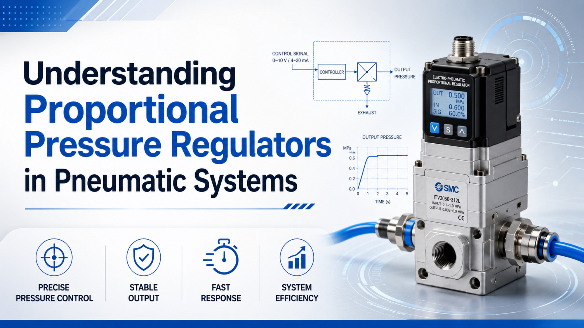
A proportional pressure regulator converts an electrical setpoint into a controlled pneumatic outlet pressure. Unlike a manually adjusted mechanical regulator, it can change pressure from the PLC for different products, process steps, or force targets.
The regulator controls pressure at its sensor. It does not directly control cylinder force, gripper force, flow, or position. Those results also depend on actuator area, friction, opposing pressure, downstream volume, restrictions, load, and mechanics. Start with the process variable, then choose pressure range, flow, exhaust behavior, signal, and acceptance test.
Key Takeaways
- A 0-10 V or 4-20 mA command is model-specific; verify scaling, impedance, supply voltage, and fault behavior.
- Pressure regulation needs both forward flow and, for rapid pressure reduction, adequate relieving or exhaust capacity.
- Cylinder force begins with
pressure x effective area, but real output also includes friction, back pressure, linkage, and structure.- Test pressure response with production tubing, downstream volume, load, supply variation, and the actual pressure sensor location.
What Is a Proportional Pressure Regulator?
Festo groups proportional pressure regulators separately from proportional flow and directional valves, and lists model-dependent voltage or current setpoints such as 0-10 V and 4-20 mA (Festo proportional valves, accessed 2026). A proportional pressure regulator is an electro-pneumatic device that adjusts outlet pressure from a variable electrical setpoint.
Most industrial designs combine three functions:
- Electronics interpret the command signal.
- An internal pressure sensor measures regulated outlet pressure.
- Fill and, where provided, exhaust valves correct the measured pressure toward the target.
That makes the unit a closed pressure loop. If outlet pressure is below target, it admits air. If pressure is above target, a relieving design exhausts air. A non-relieving design may need downstream consumption or a separate exhaust path before pressure can fall.
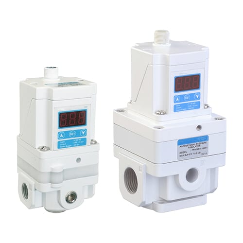
Don’t confuse this device with the broader family covered in the proportional valve motion-control guide. A proportional flow valve meters airflow. A proportional directional valve routes and meters air to actuator ports. A proportional pressure regulator targets downstream pressure.
The word proportional describes the command relationship, not guaranteed linearity across the complete pneumatic process. The regulator can track an electrical pressure target while the machine’s force or motion remains nonlinear.
How Does the Internal Pressure Loop Work?
ISO 4414 sets general rules and safety requirements for pneumatic systems and components, including their application and predictable operation (ISO 4414, 2010). Inside a proportional regulator, the relevant loop is setpoint, pressure sensor, controller, fill/exhaust element, downstream volume, and measured outlet pressure.
The simplified sequence is:
PLC setpoint -> input scaling -> internal controller
-> fill or exhaust valve -> outlet pressure sensor -> controller
The regulator reacts to pressure error. It doesn’t know whether the cylinder produced the desired clamp force or whether a gripper damaged the part. For direct force control, the machine may need a load cell or force sensor in an external loop. For pressure-only control, the internal sensor may be enough.
What happens after a setpoint step? The regulator first changes valve opening. Air then travels through its passages, tubing, fittings, and downstream chamber. Pressure rises as mass enters the volume. The internal sensor observes that rise and reduces the command as the target approaches. Delay and compressibility mean the response cannot be inferred from electronics alone.
Hysteresis, repeatability, linearity, resolution, deadband, sensitivity, and accuracy are different specifications. Compare values only when the manufacturer defines whether they refer to full scale, reading, span, or another reference and states the supply pressure, outlet volume, flow, temperature, and test method.
Why Do Relieving and Non-Relieving Designs Matter?
ISO 4414 requires pneumatic circuits to address pressure control and release of stored energy, while OSHA 29 CFR 1910.147 covers hazardous-energy control during servicing (ISO 4414, 2010; OSHA Control of Hazardous Energy, accessed 2026). A relieving regulator can vent excess downstream pressure; a non-relieving regulator cannot actively provide the same reduction path.
Suppose a recipe changes from a high pressure to a low pressure. A relieving regulator can open an internal exhaust element until the sensor reaches the lower target. Response depends on exhaust capacity, downstream volume, line restriction, and whether another source continues feeding the circuit.
A non-relieving regulator stops adding air, but trapped pressure may remain until the process consumes it or another valve vents the chamber. That can be acceptable for a slowly consuming process. It is unsuitable when the machine expects an immediate, controlled pressure decrease from the regulator alone.
| Design question | Why it matters |
|---|---|
| Must pressure decrease without downstream consumption? | Requires a defined exhaust or relieving path |
| Can the downstream circuit backfeed? | Regulator may need reverse-flow protection or a separate circuit strategy |
| Is exhausted air hazardous, dirty, or noisy? | Exhaust routing and treatment must be specified |
| Can trapped pressure move a load? | Safe energy isolation and mechanical restraint may be required |
| What happens after power or signal loss? | Fail pressure, hold, vent, or undefined behavior must be documented |
A relieving function is not a safety dump valve. It may be too small, too slow, or not safety-rated for emergency pressure removal. Define normal pressure control and safety-related exhaust as separate functions unless the selected architecture is certified and validated for both.
How Do Flow Capacity and Downstream Volume Change Response?
ISO 6358-1 provides test methods for pneumatic component flow-rate characteristics using compressible fluids (ISO 6358-1, 2013). A proportional regulator’s response depends on its fill and exhaust flow curves as well as the volume and restrictions between the regulator, sensor, and process.
Large downstream volume usually takes longer to pressurize. Small volume can respond quickly but may expose valve pulsing, sensor noise, or overshoot. Long tubing adds volume and pressure delay. Small tube ID, elbows, fittings, manifolds, and silencers restrict flow in both fill and exhaust directions.
The correct question isn’t “What is the regulator response time?” Ask instead:
- What setpoint step was applied?
- What supply pressure and initial outlet pressure were used?
- What downstream volume and tube geometry were connected?
- Was the outlet flowing or blocked?
- What error band defined settling?
- Was the measurement taken at the regulator port or at the process?
Sizing only for steady consumption can fail during fast pressure ramps. A regulator may hold pressure accurately after the process stabilizes but show a large transient drop when several actuators fill together. Conversely, a larger regulator isn’t always better. Oversized flow relative to a tiny volume can make low-pressure control difficult if the internal valves add too much mass per correction.
Proportional regulator sizing has two operating points: the peak mass flow needed to move pressure and the small corrective flow needed to hold pressure. Good selection checks both, plus exhaust capacity when the setpoint falls.
How Does Regulated Pressure Translate Into Cylinder Force?
For a pneumatic cylinder, theoretical force begins with F = P x A; extension uses full piston area while retraction uses the annular area after rod area is subtracted. The pressure difference across both sides determines net force, not the regulator setpoint alone (pressure differential and force guide).
For a single-rod cylinder:
Extension area = pi x bore^2 / 4
Retraction area = pi x (bore^2 - rod^2) / 4

Ideal extension force = cap-end pressure x extension area
Ideal retraction force = rod-end pressure x retraction area
Real process force then changes with seal friction, guide friction, opposing chamber pressure, acceleration, linkage ratio, tool geometry, contact position, and frame deflection. Pressure measured inside the regulator can also differ from pressure at the cylinder during flow.
For a clamp or gripper, establish a pressure-to-force calibration at the process datum if force matters. Apply several increasing and decreasing pressure targets and record measured force. That reveals hysteresis, breakaway friction, mechanical ratio, and whether the same pressure creates different results depending on approach direction.
Why not close the loop on pressure alone? If part height, friction, jaw position, or mechanism angle changes, the same chamber pressure can produce a different contact force. Pressure control remains useful, but it should not be advertised as direct force control without a verified mechanical relationship.
How Do You Select Pressure Range, Supply Margin, and Accuracy?
Festo’s proportional-valve catalog separates products by pressure-control range and model-specific setpoint interface rather than assigning one universal accuracy or supply margin (Festo proportional valves, accessed 2026). Select a range that covers every required target with documented supply and flow margin, but avoid an unnecessarily broad span.
A low process target on a very high-range regulator can use only a small fraction of electrical and sensor span. That may reduce useful command resolution and make offset, leakage, or deadband more visible. A range that is too narrow saturates before the maximum recipe or disturbance is reached.
Check these parameters on the exact model:
- Minimum and maximum set pressure.
- Maximum supply and allowable differential.
- Required supply-to-output margin at working flow.
- Fill flow and exhaust flow curves.
- Accuracy, linearity, repeatability, hysteresis, and sensitivity definitions.
- Minimum controllable pressure and residual pressure.
- Response test conditions and settling band.
- Air consumption, leakage, and exhaust behavior.
- Permitted medium, filtration, lubrication, humidity, and temperature.
- Electrical supply, command, monitor output, connector, and protection rating.
Don’t apply a generic 20-30 psi supply-margin rule. The needed margin depends on regulator architecture, outlet flow, pressure ratio, supply variation, and published performance curves. Measure supply pressure at the regulator inlet during the highest-flow event, not only when the machine is idle.
The working-pressure guide explains why dynamic pressure at the component is more useful than the unloaded regulator setting.
PLC Signals, Scaling, and Diagnostics
Festo lists proportional regulators with model-dependent voltage and current setpoints, including examples such as 0-10 V and 4-20 mA (Festo proportional valves, accessed 2026). The selected interface must match the PLC output electrically and must be scaled to the regulator’s exact pressure range.
Document the conversion in both directions:
PLC engineering units -> analog or digital command -> pressure setpoint
pressure monitor output -> PLC engineering units -> alarm and trend
For a 0-10 V input mapped to 0-6 bar, 5 V may represent 3 bar only if the data sheet defines a linear zero-to-full-scale mapping with no offset. A 4-20 mA model may use 4 mA as zero pressure, but some devices support configurable ranges or different behavior below the live-zero threshold. Verify, don’t assume.
Electrical checks include supply voltage, current consumption, analog common, input impedance, output type, isolation, shielding, grounding, connector pinout, cable length, and EMC instructions. Keep signal wiring away from motors and switching conductors where the installation manual requires separation.
Use the monitor output for diagnostics, not as proof of process performance. Compare commanded pressure, regulator-reported pressure, and an independent downstream sensor during commissioning. Alarm on excessive tracking error, signal loss, supply pressure loss, or output outside the permitted range when the model exposes suitable diagnostics.
Power-loss and signal-loss behavior must be written into the machine specification. Depending on the product, pressure may vent, hold temporarily, fall through leakage, or move toward another state. “Last value retained” at the PLC does not mean pneumatic energy remains controlled after electronics lose power.
Installation and Air Preparation
ISO 4414 applies to the design, installation, operation, and maintenance of pneumatic systems (ISO 4414, 2010). Install the proportional regulator according to its flow direction, orientation, air-quality limits, electrical instructions, exhaust requirements, and environmental ratings.
Use this commissioning checklist:
- Isolate and dissipate stored energy using the approved machine procedure.
- Flush or clean new tubing so chips and sealant cannot reach the internal valves.
- Install the specified upstream filtration and moisture control.
- Confirm supply, outlet, and exhaust ports before applying pressure.
- Keep the regulator close enough to the controlled volume to limit delay, while preserving service access.
- Use the specified connector, cable, grounding, and shielding method.
- Leave exhaust ports unobstructed or route them as the manual permits.
- Verify command scaling at low pressure before enabling full-range operation.
- Record inlet and outlet pressure during both fill and exhaust tests.
There is no universal 40-micron filter or -40°F pressure-dew-point requirement for every proportional regulator. Some models require finer filtration or non-lubricated air; others are intended for different gases or environments. Follow the strictest requirement among the regulator, process, and applicable air-quality specification.
Ingress protection also depends on the complete installed assembly. IEC 60529 classifies enclosure protection against access, solids, dust, and water, but an IP code does not establish chemical compatibility, functional safety, corrosion resistance, or protection with an open connector (IEC IP ratings, accessed 2026).
How Should Pressure Response Be Tuned and Tested?
ISO 4414 requires verification that pneumatic systems meet their intended function, while ISO 6358-1 provides standardized flow-characterization methods for components (ISO 4414, 2010; ISO 6358-1, 2013). Test the regulator as an installed pressure system, not as an isolated electronic box.
Many electro-pneumatic regulators contain factory-set internal control algorithms. Some expose response or gain modes; others do not allow direct PID access. Use only documented parameters. Generic advice such as adding derivative gain or increasing integral gain can destabilize the device or may be impossible to apply.
Run a controlled set of tests:
- Low-to-high pressure step at minimum and maximum expected downstream volume.
- High-to-low step to measure relieving or exhaust response.
- Load-flow disturbance while holding a constant setpoint.
- Supply-pressure variation within the permitted range.
- Increasing and decreasing pressure ramps to expose hysteresis.
- Signal loss, power loss, sensor fault, and supply loss where safe to test.
- Repeated cycles at normal and boundary temperatures.
Trend command, inlet pressure, regulator monitor output, independent downstream pressure, and process force if applicable on the same time base. Define rise time, overshoot, settling time, steady error, pressure droop under flow, and exhaust time before testing.
A single “response time” hides two different machines. Filling a downstream volume uses supply flow; reducing pressure uses exhaust flow. Specify and test both directions separately.
What Causes Oscillation, Droop, and Slow Exhaust?
ISO 4414 treats pressure control as part of the complete pneumatic system, so troubleshooting must include supply, restrictions, volume, leakage, control signal, and load rather than the regulator alone (ISO 4414, 2010). Start with synchronized pressure and command traces.
| Symptom | Possible regulator-side cause | Other causes to exclude | First measurement |
|---|---|---|---|
| Pressure oscillates | Response mode too aggressive, valve pulsing, sensor noise | Tiny downstream volume, flexible tube, unstable signal | Command and pressure at regulator outlet |
| Pressure droops under flow | Insufficient fill capacity or supply margin | Upstream filter, small tube, shared demand | Inlet and outlet pressure during demand |
| Pressure rises slowly | Restricted fill path or low supply differential | Large volume, long tube, closed downstream valve | Flow and pressure at both ends of line |
| Pressure falls slowly | Low exhaust capacity or non-relieving design | Blocked exhaust, downstream check valve, trapped branch | Outlet pressure and exhaust flow |
| Force varies at fixed pressure | Pressure error or local pressure loss | Friction, back pressure, linkage, product geometry | Both chamber pressures and measured force |
Pressure hunting can come from electrical noise, but don’t start by adding arbitrary filtering. Excessive filtering adds delay. Confirm cable routing, common reference, command stability, sensor location, pneumatic volume, and whether another regulator or valve is fighting the loop.
Pressure droop isn’t always an accuracy failure. A regulator can be accurate at zero flow and undersized at peak demand. Compare the flow curve and the measured inlet-to-outlet differential. The compressed-air pressure-drop guide helps isolate upstream restrictions.
If exhaust is slow, check whether the device is relieving, the exhaust rating, silencer restriction, tubing volume, and downstream check valves. A one-way valve placed for pressure retention can also block the intended pressure-reduction path.
The back-pressure guide covers how restricted exhaust changes actuator force and pressure response.
RFQ and Acceptance-Test Requirements
ISO 6358-1 establishes a common basis for pneumatic flow data, and ISO 4414 requires component application to match the system function and safety requirements (ISO 6358-1, 2013; ISO 4414, 2010). A useful RFQ states the operating envelope and acceptance test instead of asking only for “high precision.”
Send the supplier:
- Medium and required air quality.
- Minimum, normal, and maximum inlet pressure during flow.
- Required outlet range and normal operating setpoints.
- Continuous consumption and transient fill demand.
- Required exhaust behavior and high-to-low pressure step.
- Downstream volume, tube ID and length, fittings, and valve arrangement.
- Command interface, supply voltage, monitor output, connector, and fieldbus needs.
- Required accuracy, repeatability, hysteresis, resolution, and settling definitions.
- Ambient and medium temperature, ingress, vibration, and washdown exposure.
- Power-loss, signal-loss, and supply-loss behavior.
- Process variable: pressure, cylinder force, grip force, tension, or test pressure.
- Acceptance steps, error bands, load states, cycle count, and measurement location.
Use testable wording. “Reach 4.0 bar at the process sensor and settle within the agreed band after a 2.0-to-4.0 bar command step with the stated downstream volume” is useful. “Fast and accurate” is not.
For force applications, include bore, rod diameter, opposing chamber pressure, mechanism ratio, target force, and force measurement method. For leak or test systems, include the pressurized volume, allowable stabilization time, test duration, and leakage boundary.
Proportional Pressure Regulator FAQ
Is a proportional pressure regulator the same as a proportional flow valve?
No. A proportional pressure regulator changes fill and exhaust flow to target downstream pressure measured by an internal sensor. A proportional flow valve targets an opening or flow relationship. Pressure regulation and flow control interact, but their controlled variables and selection data are different.
Does a proportional pressure regulator control cylinder force accurately?
It controls pressure at its sensor. Theoretical cylinder force follows pressure times effective area, but real force also depends on opposing pressure, seal and guide friction, acceleration, linkage, contact geometry, and structural deflection. Use a force sensor and process calibration when force is the acceptance variable.
How much higher should supply pressure be than the output setpoint?
There is no universal 20-30 psi rule. Required margin depends on the exact regulator, flow demand, supply variation, and published performance curves. Check inlet pressure at peak flow and follow the manufacturer’s minimum differential or supply requirements across the whole operating range.
Do all proportional regulators accept 0-10 V and 4-20 mA?
No. Those are common examples, but signal options are model-specific. Confirm command range, impedance, supply voltage, analog common, monitor output, connector, isolation, diagnostics, scaling, and behavior below minimum signal or after signal loss.
Why is reducing pressure slower than increasing it?
Increasing pressure uses the regulator’s supply or fill capacity. Decreasing pressure uses its relieving or exhaust path. A non-relieving model may not actively reduce trapped pressure. Downstream volume, silencers, check valves, tubing, and continued backfeed can make the pressure fall more slowly.
How often should a proportional pressure regulator be calibrated?
Use the manufacturer’s guidance and a risk-based verification interval. Process tolerance, cycle count, contamination, temperature, regulatory requirements, drift history, and whether the regulator is used for indication or critical control all affect the interval. Monthly or annual schedules are not universal.
A proportional pressure regulator should be specified as a pressure-control subsystem. Match its range and signal, check fill and exhaust capacity, calculate the pressure-to-force relationship, define failure behavior, and validate response at the process sensor under production conditions.
External technical references and retrieval dates
Festo, Proportional Valves: Proportional pressure-regulator families and model-dependent voltage or current setpoint examples. Retrieved 2026-07-11.
ISO 4414:2010: General rules and safety requirements for pneumatic fluid-power systems and components. Retrieved 2026-07-11.
ISO 6358-1:2013: Test methods for determining pneumatic component flow-rate characteristics using compressible fluids. Retrieved 2026-07-11.
OSHA, Control of Hazardous Energy: Requirements and guidance related to 29 CFR 1910.147 and stored-energy control during servicing. Retrieved 2026-07-11.
IEC, IP Ratings: Scope of enclosure ingress-protection classification. Retrieved 2026-07-11.