

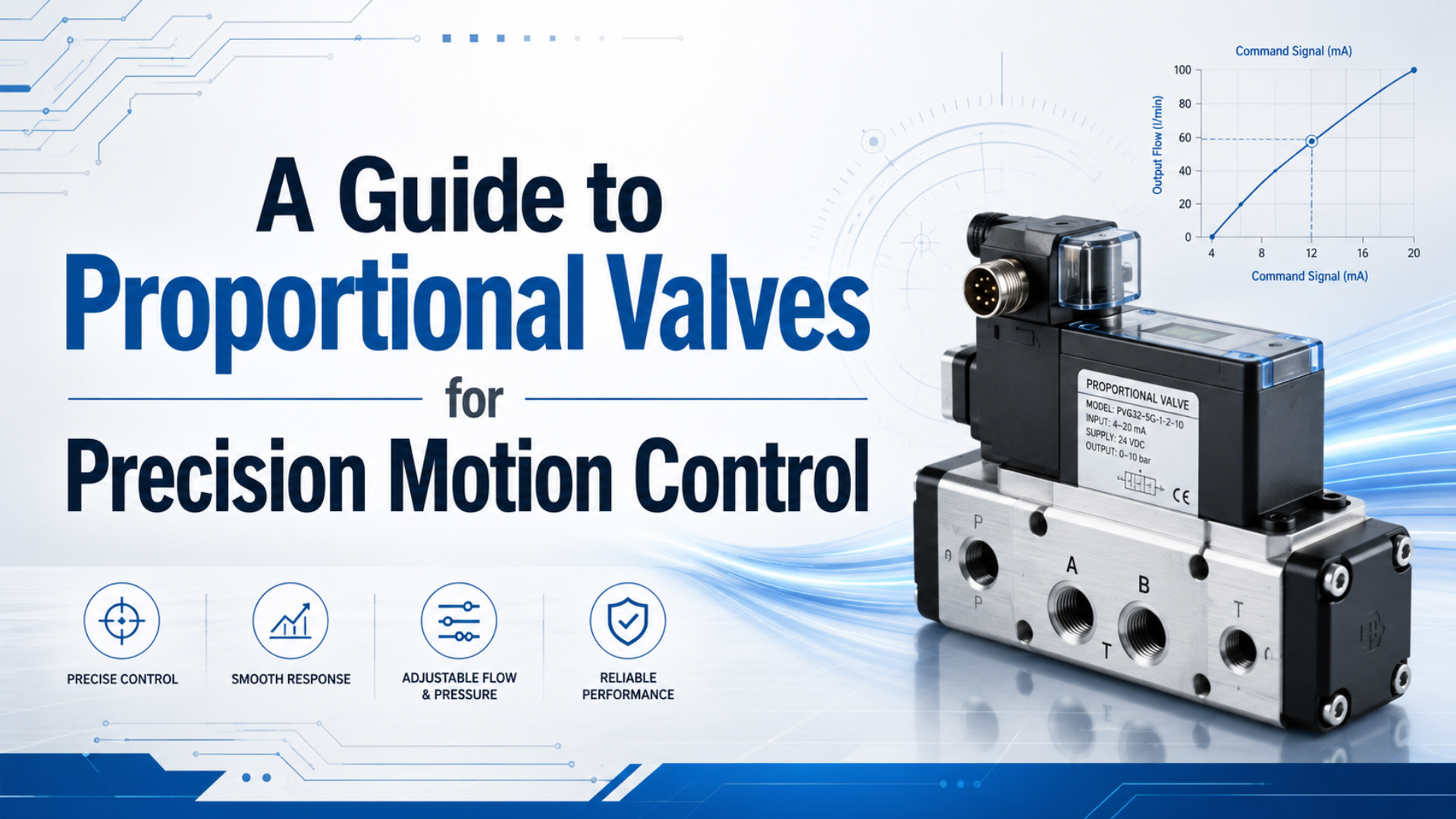
A proportional valve gives a controller a variable pneumatic output. It does not create precision motion by itself.
For speed control, the valve must meter enough air across the useful command range. For force control, pressure at the actuator must track the target under the real load. For positioning, the machine normally needs a position sensor, controller, suitable directional valve, guided actuator, stable air supply, and a defined in-position test. Select the control architecture first, then size the valve.
Key Takeaways
- Choose a proportional pressure, flow, or directional valve according to the controlled variable—not according to the word “precision.”
- Valve resolution is not machine accuracy. Friction, compressibility, dead volume, load changes, feedback, mechanics, and tuning all affect the result.
- Specify flow capacity, usable response, hysteresis, deadband, command interface, fail state, air quality, and environmental protection under stated test conditions.
- Commission the axis at working pressure, temperature, payload, tube length, exhaust restriction, and production speed.
What Is a Proportional Valve?
A proportional pneumatic valve is a control component that changes pressure, flow, or port opening in response to a variable electrical command. A standard directional solenoid valve generally switches between defined states; a proportional valve can operate at intermediate commands within its specified range.
The command may be an analog voltage, analog current, PWM-based drive, or a digital communication interface. The available choices are model-specific. Festo lists proportional-valve families with voltage and current setpoints, while Bürkert’s Type 8605 electronics convert a standard input signal into PWM coil drive for compatible proportional valves (Festo proportional valves, accessed 2026; Bürkert Type 8605, accessed 2026).
Inside the valve, electronics regulate current to a solenoid or another actuator. That actuator moves a spool, poppet, needle, or similar control element. The resulting opening changes conductance, flow, or pressure. SMC’s PVQ documentation shows applied current changing electromagnetic force, armature stroke, and flow rate in a direct-operated proportional flow valve (SMC PVQ, accessed 2026).
Intermediate commands are not infinite resolution. Real valves have hysteresis, repeatability limits, deadband, leakage, saturation, response delay, and a finite control range. Read those values from the selected model’s data sheet and confirm how the manufacturer measured them.
Select the Controlled Variable Before the Valve
The correct valve family follows the quantity the machine must control. “Smooth motion” and “high accuracy” are outcomes, not valve specifications.
| Control objective | Typical valve type | What the command changes | What must be measured for closed-loop control |
|---|---|---|---|
| Adjustable actuator speed | Proportional flow valve | Supply or exhaust flow restriction | Position or velocity |
| Adjustable pushing or clamping force | Proportional pressure regulator | Downstream pressure | Pressure, force, or both |
| Bidirectional velocity and position | Proportional directional valve | Flow direction and opening | Position or velocity, often with pressure diagnostics |
| Process gas or liquid dosing | Media-compatible proportional valve | Orifice opening and flow | Flow, pressure, or process output |
A flow valve can shape cylinder speed, but speed will still change when supply pressure, load, friction, or exhaust back pressure changes. A pressure regulator can command force approximately through force = pressure x effective area, but seal friction, opposing chamber pressure, mechanism ratio, and contact geometry affect delivered force. A proportional directional valve can drive both sides of an actuator, but repeatable mid-stroke positioning still requires feedback and control logic.
The pressure differential and cylinder force guide explains why supply pressure alone cannot represent the net force available at the mechanism.
This boundary prevents a common selection error: buying a proportional component when the application actually needs a closed-loop motion system. The controlled variable determines the valve family; the required process result determines whether feedback is necessary.
Open-Loop Control and Closed-Loop Motion Are Not the Same
Open-loop control is a command strategy that does not correct valve output from the measured process result. It is often sufficient for selectable speeds, soft start and stop, adjustable pressure, or a process that finishes against a mechanical stop.
Closed-loop control is a feedback strategy that measures the result, compares it with a target, and changes the command to reduce error. A pneumatic positioning loop typically contains:
- A commanded position or motion profile.
- A controller that calculates position or velocity error.
- A proportional directional valve or coordinated valve arrangement.
- A pneumatic actuator and guided mechanical load.
- A continuous position sensor.
- In-position, timeout, pressure, and safe-state logic.
Festo describes a proportional directional valve that converts an analog input into a corresponding valve opening and can form a pneumatic positioning system with an external controller and displacement encoder. That wording is important: the positioning function belongs to the assembled loop, not to the valve alone (Festo proportional valves, accessed 2026).
For a deeper treatment of position feedback and controller architecture, see the servo-controlled pneumatic positioning guide. Applications focused on shaping rodless-cylinder speed rather than position can use the proportional flow-control guide.
Which Applications Are a Good Fit?
Proportional control fits processes that need adjustable output between two switching states and can justify the additional electronics, commissioning, and diagnostics.
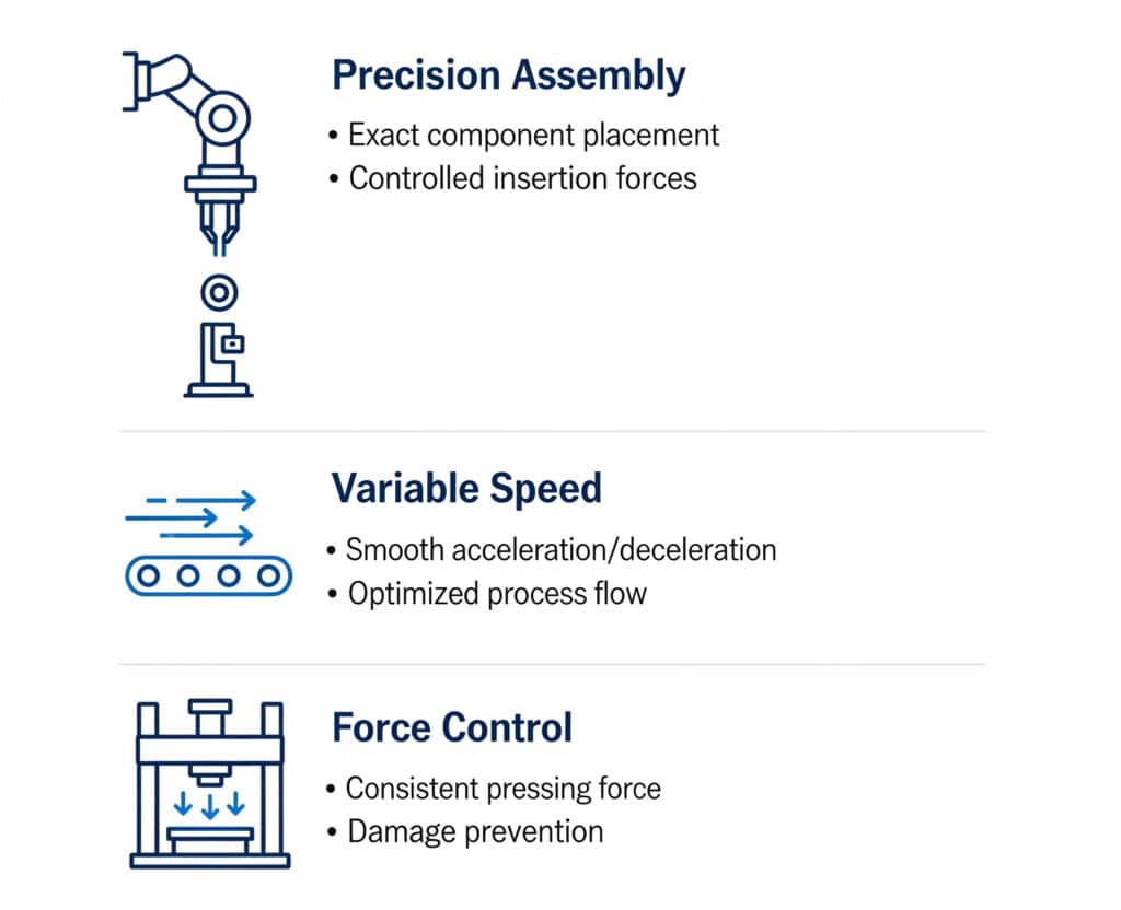
Typical candidates include:
- Variable-speed transfer: fast travel through the open part of a stroke, followed by a slower approach to a product or stop.
- Controlled pressing or clamping: adjustable pressure or force targets for different recipes.
- Tension and web handling: pressure or flow correction based on a process sensor.
- Test equipment: programmable pressure ramps and repeatable load sequences.
- Long-stroke guided motion: acceleration and deceleration profiles that reduce impact and load disturbance.
- Process dosing: controlled gas or liquid flow with a valve designed for the medium.
The image categories are starting points, not automatic guarantees. “Exact placement” requires a complete positioning loop and suitable mechanics. “Consistent pressing force” requires force or pressure feedback when friction, contact height, or opposing pressure can change.
A standard on/off valve remains the better choice when the actuator only needs two end positions, cycle conditions are stable, and fixed speed controllers meet the process requirement. An electric servo axis is often a stronger fit when the application needs tightly controlled multi-point trajectories, stiffness at standstill, simple commissioning across large load changes, or a tolerance beyond what the pneumatic system can demonstrate.
How Do You Size a Proportional Valve?
Size the valve for the worst required motion at the actual upstream and downstream pressures. Port size alone is not a flow rating.
ISO 6358 defines test methods and flow-rate characteristics for components using compressible fluids. Depending on the manufacturer and market, a valve may be described with sonic conductance and critical pressure ratio, standardized flow, Cv, Kv, or a manufacturer-specific nominal flow condition (ISO 6358-1, accessed 2026).
Collect these inputs before selecting a valve:
| Input | Why it matters | RFQ detail |
|---|---|---|
| Cylinder bore and rod | Determines effective area and chamber volume | Bore, rod diameter, cylinder type |
| Stroke and target time | Establishes average and peak flow demand | Full profile, not only cycles per minute |
| Moving mass and orientation | Changes acceleration, runaway risk, and force | Payload, tooling, vertical/horizontal axis |
| Supply and exhaust pressure | Determines available pressure ratio and flow | Dynamic readings during motion |
| Tube and fitting path | Adds volume, delay, and restriction | Inside diameter, length, elbows, silencers |
| Control objective | Separates pressure, flow, and position functions | Allowed speed, force, or position error |
| Command interface | Must match the controller | 0–10 V, 4–20 mA, fieldbus, or model-specific input |
| Feedback and update path | Sets the measurable loop behavior | Sensor type, range, resolution, controller |
Do not size only for steady travel. Acceleration can demand higher flow; deceleration may require controlled exhaust; a vertical load may overrun a meter-in circuit; and a silencer can become the dominant exhaust restriction. The meter-in versus meter-out guide covers the load-direction implications in more detail.
Valve sizing has two limits, not one. If the valve is too small, the command reaches saturation before the actuator reaches target speed. If it is much too large, a small electrical command change can create a large pneumatic change, leaving little usable resolution around low speed. Check maximum capacity and minimum controllable output together.
The valve-to-actuator volume also matters. Long tubing introduces compressible volume and transport delay between the command and cylinder pressure response. Mounting the valve closer can improve response, provided safety, heat, contamination, wiring, and service access remain acceptable.
Which Data-Sheet Specifications Matter Most?
Compare specifications only when their definitions and test conditions match. A response time measured from an electrical step to initial spool movement is not the same as time to reach a pressure band or complete a loaded cylinder move.
Review at least these parameters:
- Rated flow characteristic: conductance, nominal flow, Cv, or Kv under stated conditions.
- Control range: the command region over which output is usefully controllable.
- Hysteresis: the difference in output when approaching the same command from increasing and decreasing directions.
- Repeatability: output variation when the same command is applied repeatedly under the stated test.
- Deadband or threshold: command change that produces little or no useful output change.
- Response or bandwidth: the dynamic definition, input amplitude, pressure, and test load used by the manufacturer.
- Leakage: internal or external leakage in specified states.
- Pressure and temperature range: allowable supply, outlet, pilot, ambient, and medium conditions.
- Air quality: filtration, lubrication, moisture, and contamination limits.
- Electrical interface: signal range, input impedance, supply voltage, connector, diagnostics, and fieldbus profile.
- Fail state: behavior after loss of electrical power, command, network, pilot air, or supply pressure.
- Enclosure protection: the exact assembly and connector configuration covered by the IP rating.
IEC 60529 classifies enclosure protection against access, solid objects, dust, and water. An IP code does not describe functional safety, corrosion resistance, washdown chemical compatibility, or the protection of an incomplete connector installation (IEC IP ratings, accessed 2026).
Ask suppliers for the characteristic curves, not just a single maximum value. A maximum-flow number cannot show low-command controllability, pressure sensitivity, hysteresis, or the response of the complete valve-electronics package.
How Should the PLC and Feedback Be Integrated?
Match the controller to the exact valve interface. Confirm signal range, common reference, input impedance, isolation, update behavior, scaling, and fault detection before wiring.
For an analog interface, document the engineering-unit conversion:
PLC command (%) -> analog output -> valve command (%) -> measured pressure or flowDo not assume that 50% electrical command creates 50% cylinder speed. Valve flow curves may be nonlinear, cylinder speed depends on load and pressure, and static friction can create a threshold before motion begins. Commission a command-to-output map on the machine if the application is open loop.
For closed-loop position control, the signal chain becomes:
motion target -> controller -> valve command -> pressure and flow
-> actuator and load -> position sensor -> controller
Sensor resolution alone does not establish positioning accuracy. Mounting compliance, guide clearance, fixture deflection, backlash, sampling, filtering, time delay, valve deadband, cylinder friction, and temperature all sit between the sensor count and the process result. The most useful accuracy number therefore belongs to the loaded machine at the process datum, not to the valve or sensor in isolation.
Useful controller diagnostics include command saturation, position error, following-error timeout, supply-pressure status, sensor plausibility, communication status, and in-position dwell time. A safe design must also define what happens when power or feedback disappears. That decision belongs in the machine risk assessment; it cannot be inferred from normal operating performance.
How Do You Commission the Motion Loop?
Commission from the pneumatic hardware outward. Tuning cannot compensate for an undersized exhaust path, unstable supply, a binding guide, loose mechanics, or a sensor mounted to the wrong datum.
Use this sequence:
- Verify mechanics. Check alignment, guidance, payload center of gravity, end stops, cushioning, and free movement across the stroke.
- Verify the air path. Record dynamic supply pressure, filtration, tube ID and length, fitting restrictions, exhaust hardware, and leakage.
- Confirm I/O scaling. Test command polarity, zero, span, sensor direction, engineering units, and signal-loss behavior.
- Begin with conservative limits. Restrict command, speed, acceleration, and travel while checking direction and fault logic.
- Map open-loop behavior. Record pressure, flow, or speed at several increasing and decreasing commands to expose threshold and hysteresis.
- Close one loop at a time. Establish stable feedback and basic proportional action before adding integral, derivative, feedforward, or compensation features.
- Test the real operating envelope. Use minimum and maximum payload, normal temperature range, expected supply variation, and production tubing.
- Run acceptance cycles. Measure the process output, not only the sensor signal, and record pass/fail limits.
Generic PID values are unsafe shortcuts. Controller update rate, filtering, proportional gain, integral action, derivative action, feedforward, and dead-zone compensation depend on the actual valve, sensor, actuator volume, load, delay, and motion profile.
Oscillation does not always mean “too much gain.” Friction-induced stick-slip, sensor noise, mechanical compliance, air trapped in long lines, exhaust restriction, and a valve operating near deadband can produce similar symptoms. Capture the command, measured position, pressure, and error on the same time base before changing the tuning.
Define Precision With an Acceptance Test
Replace “high precision” with a measurable condition. A useful requirement states the target, allowed error, payload, approach direction, speed, dwell time, temperature, pressure, number of cycles, and measurement method.
| Weak requirement | Testable requirement |
|---|---|
| Accurate positioning | Reach each listed target within the specified error band after the stated dwell time |
| Fast response | Complete the defined move and settle within a stated time without exceeding the overshoot limit |
| Repeatable force | Maintain the measured force band over the specified contact travel, payload, and cycle count |
| Smooth motion | Stay within stated acceleration, jerk, or product-disturbance limits across the motion profile |
Separate four quantities:
- Resolution: the smallest command or measurement increment.
- Repeatability: how closely repeated results agree under the same stated conditions.
- Accuracy: how close the measured result is to the reference target.
- Settling behavior: how long the output takes to enter and remain inside the allowed band.
A valve can have fine command resolution while the machine has poor accuracy. Conversely, a mechanically constrained end-stop application may repeat well with a simple valve because the hard stop defines the final position. The acceptance test must measure the output the process actually uses.
What Should Be Included in a Proportional-Valve RFQ?
Send enough information for the supplier to evaluate the control loop and the pneumatic operating point:
- Medium and required air-quality class.
- Minimum, normal, and maximum supply pressure during flow.
- Controlled variable: pressure, force, flow, speed, or position.
- Cylinder type, bore, rod, stroke, mounting, guide, orientation, and payload.
- Target positions, speed profile, cycle time, dwell, and duty cycle.
- Tube inside diameter, length, fittings, manifold, and exhaust hardware.
- Required flow or enough geometry and timing data to calculate it.
- Command signal, power supply, connector, network, and diagnostic needs.
- Sensor type, range, output, update behavior, and mounting datum.
- Environmental temperature, ingress, vibration, corrosion, and washdown conditions.
- Required fail state and machine safety constraints.
- Acceptance window, load cases, number of cycles, and measurement method.
This information allows the valve, electronics, actuator, and controller to be assessed together. It also exposes when the requirement belongs to an electric motion axis, a standard on/off pneumatic circuit, or a complete servo-pneumatic package rather than a standalone proportional valve.
Proportional Valve FAQ
Can a proportional valve position a pneumatic cylinder by itself?
No. A proportional valve supplies a variable pressure, flow, or directional command. Repeatable intermediate positioning normally requires continuous position feedback, a controller, appropriate mechanics, and an acceptance definition. End-to-end motion against hard stops may not need that full architecture.
Is a proportional valve the same as a servo valve?
Terminology varies by manufacturer, so compare functions and specifications instead of relying on the label. A servo-pneumatic system describes a closed-loop architecture. It may use a proportional directional valve or a valve marketed as a servo valve, together with feedback and a controller.
Should I choose 0–10 V or 4–20 mA control?
Choose an interface supported by both the exact valve and the controller. Review cable length, electrical noise, grounding, diagnostics, input impedance, resolution, isolation, and failure detection. A current loop can be useful over longer industrial runs, but interface choice alone does not establish motion accuracy.
Does a larger proportional valve improve response?
Not automatically. An undersized valve can limit flow and cause command saturation, while an oversized valve can compress useful control into a small part of the command range. Size the valve for the pressure ratio and required flow, then check low-command controllability and dynamic data.
Do proportional valves reduce compressed-air consumption?
They can enable lower pressure, staged pressure, controlled profiles, or other strategies that reduce air in a specific process. A proportional valve does not inherently save air. Measure standard-air volume per accepted cycle before and after the change while holding load, timing, pressure, and production conditions constant.
What causes hunting near the target position?
Possible causes include excessive loop gain, valve deadband, stick-slip friction, sensor noise, mechanical compliance, pneumatic delay, poor filtering, integral windup, or unstable supply pressure. Trend command, feedback, error, and actuator pressures together before changing parameters.
The correct proportional valve is the one that controls the required variable across the real operating range and passes a documented machine-level test. Start with the control objective, establish the flow and feedback architecture, match the electrical interface, and commission under production conditions.
External technical references and retrieval dates
Festo, Proportional Valves: Proportional pressure, flow, and directional valve families; setpoint interfaces; positioning architecture with controller and encoder. Retrieved 2026-07-11.
SMC, PVQ Series Proportional Solenoid Valve: Relationship between applied current, electromagnetic attraction, armature stroke, and flow rate. Retrieved 2026-07-11.
Bürkert, Type 8605 Control Electronics: Standard input signals, PWM coil control, and compatible proportional-valve electronics. Retrieved 2026-07-11.
ISO 6358-1: Test methods for determining flow-rate characteristics of pneumatic components using compressible fluids. Retrieved 2026-07-11.
IEC, IP Ratings: Scope of ingress-protection classification for equipment enclosures. Retrieved 2026-07-11.