

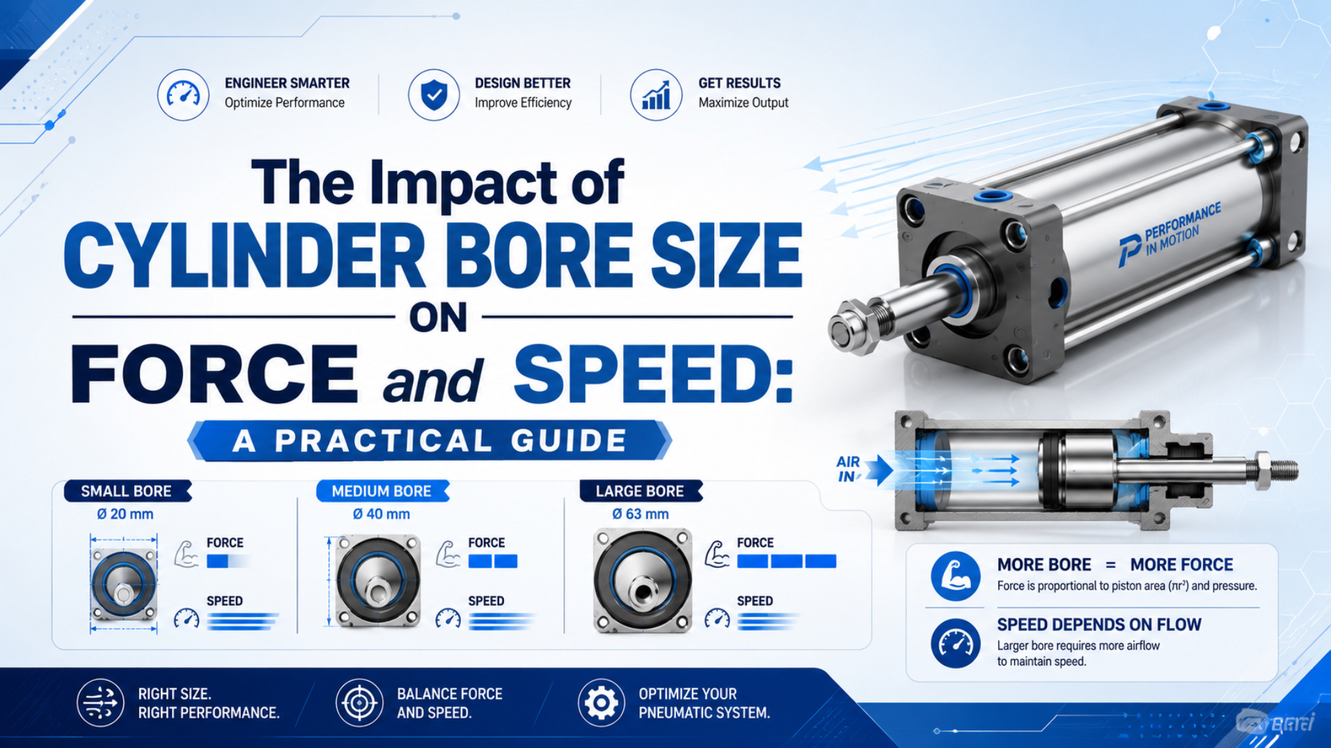
Cylinder bore size directly sets piston area, so it changes theoretical force and chamber volume with the square of bore diameter. It does not, by itself, set real cylinder speed. A larger bore moves more slowly only when the available working-pressure flow remains unchanged; a valve, tube, fitting, exhaust path, or speed controller can become the actual limit.
That distinction prevents two common sizing errors. The first is choosing a large bore from force alone and discovering that the existing valve cannot fill it within the required stroke time. The second is choosing a small bore because it looks faster on paper, then finding that pressure collapses under load. For the broader equation library, use the pneumatic cylinder formula guide. This article focuses on one decision: what changes when bore changes and the rest of the circuit does not.
Key Takeaways
- At unchanged pressure, theoretical extension force follows bore diameter squared.
- At unchanged actual chamber flow, piston speed follows the inverse of piston area.
- ISO 15552 covers 32-320 mm detachable-mounting cylinders, but not application flow checks (ISO 15552, confirmed 2025).
- Select bore from load, then verify valve flow, tubing, exhaust, cushioning, and stroke time.
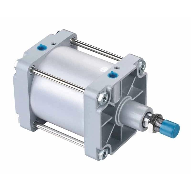
ISO 15552:2018 covers detachable-mounting pneumatic cylinders with bores from 32 mm to 320 mm and a maximum rated pressure of 1,000 kPa (10 bar). The standard was confirmed in 2025, but its scope is dimensional interchangeability; it does not replace application-specific force, flow, mounting, or cushioning checks (ISO 15552, confirmed 2025).
Bore Size Changes Area Before It Changes Anything Else
Piston area is the link between bore, force, speed, and air demand. For a round piston, AutomationDirect uses the same pressure-area relationship for cylinder sizing (AutomationDirect Cylinder Sizing, accessed 2026-07-11):
Piston area = pi x bore^2 / 4
Extension theoretical force = pressure differential x piston area
Retraction area = piston area - rod area
Retraction theoretical force = pressure differential x retraction area
The square is the important part. Moving from a 40 mm bore to an 80 mm bore does not double the area; it multiplies area by four. As a result, theoretical extension force also rises fourfold at the same pressure differential. Chamber volume per millimeter of stroke rises by the same factor.
AutomationDirect defines cylinder extension force as effective piston area multiplied by differential pressure. Its sizing page also shows why pull force is lower on a single-rod cylinder: the rod blocks part of the pressure-receiving area during retraction (AutomationDirect Cylinder Sizing, accessed 2026-07-11).
The word differential matters. If the cap end is at 6 bar gauge while the exhausting rod end carries 0.8 bar of back pressure, the piston does not experience the same net force as a calculation that assumes 6 bar on one side and atmosphere on the other. In particular, seal resistance, guide friction, acceleration, gravity, and installation geometry reduce the load that can be moved reliably.
What Happens to Force When Bore Increases?
At 0.6 MPa differential pressure, theoretical extension force rises from about 483 N at 32 mm bore to 3,016 N at 80 mm bore. The figures below are calculated from the pressure-area relationship published by AutomationDirect; they are not safe working-load ratings (AutomationDirect Cylinder Sizing, accessed 2026-07-11).
Citation capsule: Holding pressure constant isolates the bore effect. From 32 mm to 80 mm, piston area and theoretical extension force rise by 6.25 times. Holding actual chamber flow constant reverses the index: the first-pass speed falls to 16% because the same flow is divided by 6.25 times the area.
Engineering insight: The force and speed columns are not competing catalog ratings. They are two controlled comparisons with different fixed boundaries: pressure for force, actual chamber flow for speed.
| Bore | Piston area | Theoretical force at 0.6 MPa | Area and force index | Speed index at identical actual flow |
|---|---|---|---|---|
| 32 mm | 804 mm2 | 483 N | 1.00 | 1.00 |
| 40 mm | 1,257 mm2 | 754 N | 1.56 | 0.64 |
| 50 mm | 1,963 mm2 | 1,178 N | 2.44 | 0.41 |
| 63 mm | 3,117 mm2 | 1,870 N | 3.88 | 0.26 |
| 80 mm | 5,027 mm2 | 3,016 N | 6.25 | 0.16 |
The final column is deliberately conditional. It assumes equal actual flow into the chamber. In other words, the larger cylinder can achieve the same speed if it receives proportionally more flow. If its ports, valve, and tubing remain unchanged, the extra volume normally makes the stroke slower.
A worked bore selection
For example, consider a dynamic horizontal transfer with a worst credible load of 800 N and an expected pressure differential of 0.6 MPa. SMC’s general cylinder-selection guide recommends a load ratio of 0.5 or below for dynamic operation. It also notes that high-speed operation may require an even lower ratio (SMC Air Cylinders Model Selection, accessed 2026-07-11).
Using 0.5 as the selected method:
Required theoretical force = 800 N / 0.5 = 1,600 N
Required piston area = 1,600 N / 0.6 N/mm2 = 2,667 mm2
Calculated bore = sqrt(4 x 2,667 / pi) = 58.3 mm
Therefore, the next applicable catalog bore might be 63 mm. Its theoretical extension force at 0.6 MPa is about 1,870 N, producing a load ratio near 0.43 for the 800 N case. That is only the force gate. That said, the designer still has to check retraction force, rod stability, mounting, side load, cushion energy, dynamic pressure, and cycle time. The force-factor sizing guide explains how to keep theoretical force and allowable load ratio separate.
A Larger Bore Is Not Automatically Slower
Cylinder speed is a flow-and-area relationship, not a bore-only property. SMC publishes the first-pass relation s = 28.8q / A, where speed is in inches per second, q is airflow in SCFM, and A is piston area in square inches. SMC explicitly states that inlet pressure must be held constant and that port and tubing sizes also affect speed (SMC Control Air Flow of Cylinders, accessed 2026-07-11).
Citation capsule: SMC separates output force from speed: pressure acting on area produces force, while flow divided by area provides a first-pass speed estimate. The published relation assumes constant inlet pressure and does not erase port, tubing, exhaust, load, or cushion effects (SMC Control Air Flow of Cylinders).
In unit-independent form, the core relationship is:
Piston speed = actual chamber flow / effective piston area
Stroke time = stroke / piston speed
The word actual is essential. A valve catalog may state flow in SCFM or L/min (ANR), which refers to standard or free air. Specifically, the cylinder chamber receives a smaller actual volume flow at working pressure. Convert on a consistent reference basis before dividing by piston area. NIST also warns that standard gas-flow units can use different reference temperatures, so the unit basis belongs on the worksheet (NIST Pressure and Gas Flow Conversions, updated 2025).
Notably, SMC’s own selection example demonstrates the scale of the problem: a 50 mm bore cylinder at 0.5 MPa and 500 mm/s requires approximately 350 L/min (ANR). That is required stroke flow, not average air consumption over a full machine cycle (SMC Air Cylinders Model Selection, accessed 2026-07-11).
Why the same valve behaves differently after a bore change
If a 32 mm cylinder and an 80 mm cylinder receive the same actual chamber flow, the 80 mm piston has 6.25 times the area. Consequently, its first-pass speed is only 16% of the 32 mm value. Thus, the larger cylinder is not inherently slow; the unchanged flow path has become undersized relative to chamber area.
In addition, real motion adds more constraints:
- The valve must pass enough supply and exhaust flow at the actual upstream and downstream pressures.
- Tube ID, tube length, fittings, quick couplers, silencers, and manifolds add restriction.
- Meter-out control creates back pressure to stabilize motion, but that back pressure reduces net force.
- Cushion adjustment can dominate the final part of the stroke even when mid-stroke speed is adequate.
- Load ratio and seal friction affect acceleration and the time needed to build useful force.
- Retraction may be faster because rod-side area and chamber volume are smaller, but asymmetric valve or exhaust conditions can reverse that expectation.
The high-speed cylinder specification checklist covers cushion energy and motion timing in more detail. For a valve-centered calculation, use the Cv sizing guide.
Fixed-Flow Comparison: 32 to 80 mm
The most useful bore comparison holds one boundary constant at a time. This method follows SMC’s separation of theoretical output, required flow, and air consumption into different selection calculations (SMC Air Cylinders Model Selection, accessed 2026-07-11). Mixing a fixed-pressure force calculation with an unspecified-flow speed claim creates a result that cannot be checked.
Engineering insight: A bore change should trigger three separate recalculations: force at dynamic pressure, required flow at target stroke time, and standard-reference air per accepted cycle.
| Comparison boundary | What remains fixed | What a larger bore does | What must be rechecked |
|---|---|---|---|
| Force comparison | Pressure differential | Raises theoretical force with area | Load ratio, back pressure, mounting |
| Speed comparison | Actual chamber flow | Lowers first-pass speed | Valve, tubing, exhaust, cushion |
| Target-time comparison | Stroke and stroke time | Raises required flow | Valve conductance, pressure drop, FRL |
| Air-per-cycle comparison | Stroke and pressure ratio | Raises charged air volume | Rod diameter, tubing volume, cycle rate |
| Energy comparison | Accepted production output | Usually raises actuator demand | Leaks, idle flow, rejects, compressor efficiency |
For instance, this separation helps during troubleshooting. A weak cylinder with normal cycle time points toward load, friction, or pressure differential. A strong but slow cylinder points toward flow capacity, exhaust restriction, or cushion settings. A slow cylinder whose pressure falls during motion may have both problems. Measure pressure at both actuator ports during the loaded portion of the stroke instead of relying on the static regulator gauge.
Similarly, CAGI identifies piping, fittings, filters, dryers, and other components as sources of pressure drop and recommends correcting restrictions before simply increasing compressor discharge pressure (CAGI Pressure Drop Technical Brief, accessed 2026-07-11). The pneumatic pressure-drop troubleshooting guide provides a machine-side measurement sequence.
How Much More Air Does a Larger Bore Use?
At unchanged stroke and pressure ratio, cylinder air per cycle rises approximately with chamber area. A complete double-acting cycle includes the full-bore extension chamber and the smaller rod-side annular chamber. SMC’s calculation also includes switched tubing between the valve and cylinder (SMC Air Cylinders Model Selection, accessed 2026-07-11).
SMC separates air consumption from required air volume. Air consumption supports compressor and running-cost estimates. In contrast, required air volume is the flow needed to move the load at a specified speed and supports FRL, upstream piping, and valve selection (SMC Air Cylinders Model Selection, accessed 2026-07-11).
Citation capsule: SMC defines air consumption as the volume charged into the cylinder and valve-to-cylinder piping during operation. Required air volume is a different quantity: the flow needed for a specified speed. Bore, stroke, pressure, tubing, and stroke time therefore belong to one sizing worksheet, but not one interchangeable number.
For example, consider a 50 mm bore, 20 mm rod, 200 mm stroke cylinder at 0.6 MPa gauge. Using an approximate absolute-pressure ratio of 7 referenced to 0.1 MPa absolute and assuming equal temperature:
Extension swept volume = 0.393 L
Retraction swept volume = 0.330 L
Cylinder-only approximate free-air equivalent = (0.393 + 0.330) x 7
                                              = 5.06 L referenced to 0.1 MPa absolute
At 20 complete cycles/min = about 101 L/min on the same basis
This is not a formal ANR, NL, or SCF value unless the applicable reference temperature and other reporting conditions are also stated. Importantly, the calculation excludes valve-to-cylinder tubing, leakage, pilot air, blow-off, and simultaneous machine loads. It also assumes both chambers reach the stated pressure. Festo’s cylinder air-consumption tool likewise uses cylinder size, stroke, and operating pressure as core inputs, reinforcing that bore alone cannot produce a cost estimate (Festo Cylinder Air Consumption, accessed 2026-07-11).
For a full boundary that includes tubing and measured machine flow, see the double-acting cylinder air-consumption guide. Similarly, a flow controller may change speed without reducing the final mass admitted to a chamber that still reaches the same pressure.
Select Bore From Load, Then Prove the Flow Path
The reliable sequence is load first, bore second, flow third, and machine validation last. SMC treats bore selection and required air volume as separate steps for this reason (SMC Air Cylinders Model Selection, accessed 2026-07-11). Selecting bore from speed alone can leave no force reserve; selecting bore from theoretical force alone can create an unserviceable flow demand.
- Define the motion. Record load magnitude, direction, orientation, acceleration, stroke, target time, dwell, and cycles per minute.
- Use dynamic pressure. Estimate the lowest cap-end pressure and the highest exhaust back pressure during the demanding part of motion.
- Choose one force-sizing method. Apply the selected manufacturer’s load ratio or a documented application-specific force margin. Do not stack overlapping deductions.
- Calculate both directions. Subtract rod area for retraction and include spring force where applicable.
- Move to a real catalog bore. Check ISO family, mounting envelope, port size, rod diameter, and replacement requirements.
- Calculate target flow. Convert chamber volume and target stroke time into required standard flow on a stated reference basis.
- Check every restriction. Review valve data at the relevant pressure ratio, tube ID and length, fittings, manifolds, speed controllers, and silencers.
- Check end-of-stroke energy. Larger bore can increase acceleration and impact even when average speed is unchanged.
- Test the machine. Record stroke time, both port pressures, load, cushion setting, and acceptance result.
In particular, do not assume a guided actuator eliminates side load. Accordingly, the guide carries external moments and transverse forces within stated limits; bore still determines pneumatic force, while the guide and carriage determine allowable loading. Likewise, a rodless cylinder solves an envelope problem, not a free-force or free-speed problem. Its bore, seal drag, carriage load, porting, and cushion data still require review.
When Force and Speed Conflict, Change the Right Variable
When a larger bore passes the load check but misses cycle time, the next move depends on the failed boundary. CAGI recommends removing restrictions and diagnosing pressure drop before increasing compressor discharge pressure (CAGI Pressure Drop Technical Brief, accessed 2026-07-11). Use evidence from pressure and timing measurements instead of defaulting to higher plant pressure.
Engineering insight: Pressure and timing traces identify which variable to change. Low net force with adequate flow calls for a load-path or pressure-differential review; adequate force with excessive stroke time calls for a flow-path review.
| Observed result | Likely boundary | First actions |
|---|---|---|
| Pressure holds, motion is slow | Flow or exhaust restriction | Check valve, tube ID, fittings, silencer, meter-out setting |
| Supply pressure falls during motion | Upstream conductance or local storage | Measure across FRL and valve; shorten/enlarge line; review receiver strategy |
| Supply holds but net force is low | Back pressure, friction, geometry, load | Measure both ports; inspect alignment and guide load |
| Mid-stroke is fast, final stroke is slow | Cushion setting or trapped exhaust | Review cushion needle and end-of-stroke energy |
| Speed passes, air use is high | Oversized bore, long stroke, high pressure, excess cycling | Recheck load case and measure air per accepted cycle |
| Smaller bore needs excessive pressure | Insufficient area or poor load path | Choose a larger bore or reduce the mechanical load/friction |
Alternatively, a pressure booster may be appropriate for a small, intermittent, isolated high-pressure demand, but it is not a default speed solution. The booster needs inlet flow and time to recover, and higher downstream pressure increases stored energy and air demand. Multiple smaller cylinders can distribute load, yet they add synchronization, plumbing, alignment, and control requirements. In other words, neither option should replace a complete force-and-flow calculation.
Meanwhile, meter-out control is usually preferred for stable pneumatic cylinder speed because it maintains exhaust back pressure. That same back pressure reduces net force, so adjust it while monitoring motion and both port pressures. The meter-in versus meter-out guide explains the stability trade-off.
Bore Size RFQ Checklist
A supplier can check bore, valve, and circuit compatibility only when the request defines the load and time boundary. ISO 15552 defines interchangeability dimensions, while SMC’s selection method adds load, speed, piping, and cushion checks (ISO 15552; SMC Air Cylinders Model Selection). Accordingly, send these values together:
- Cylinder type, current model, and required standard or interchangeability family.
- Bore, rod diameter, stroke, mounting style, port size, and cushion type.
- Load magnitude, direction, orientation, guide arrangement, and external moments.
- Required extension time, retraction time, dwell, and cycles per minute.
- Minimum measured supply pressure during motion and expected exhaust condition.
- Valve model, flow specification, manifold arrangement, and switching time.
- Tube OD and ID, length to each port, fittings, quick couplers, controllers, and silencers.
- Ambient temperature, contamination, washdown, corrosion, and lubrication conditions.
- Failure behavior, vertical-load controls, guarding, and machine risk requirements.
- Acceptance criteria for stroke time, pressure, impact, repeatability, and air use.
Finally, if the request is a replacement, include the old cylinder nameplate and mounting dimensions. ISO 15552 supports dimensional interchangeability within its scope, but port position, sensor groove, rod-end thread, cushion adjustment, and accessory stack still need comparison. The ISO 15552 interchangeability checklist covers those details.
For a bore-and-flow review, send the completed worksheet through the pneumatic application contact form. Include the current cylinder and valve model numbers so the response can distinguish an actuator limit from a circuit restriction.
FAQ: Cylinder Bore Size, Force, and Speed
The answers below keep force, speed, and air use on separate calculation boundaries. AutomationDirect supports the pressure-area force relation, while SMC separates required stroke flow from total air consumption (AutomationDirect Cylinder Sizing; SMC Air Cylinders Model Selection).
Does doubling cylinder bore double the force?
No. At unchanged pressure differential, doubling bore diameter quadruples piston area and theoretical extension force because area follows diameter squared. Therefore, usable load remains lower after the selected load ratio, friction, back pressure, acceleration, and installation effects are considered.
Why can a larger-bore cylinder move more slowly?
A larger bore has more chamber area and volume. If actual flow remains unchanged, speed falls because speed equals actual chamber flow divided by effective area. A larger valve and less restrictive tubing or exhaust path can supply more flow, so the larger cylinder is not automatically slower.
Should cylinder force use regulator pressure?
Regulator pressure is acceptable for an early estimate. Final sizing should use the pressure differential across the piston during the demanding part of motion. Measure or estimate both actuator-port pressures because supply loss and exhaust back pressure reduce net force.
Does a larger bore always use more compressed air?
At the same stroke, pressure ratio, rod configuration, and cycle count, a larger bore charges more chamber volume and therefore uses more standard air per cycle. A complete calculation also includes the rod-side chamber, switched tubing, leakage, pilot air, and the actual number of cycles.
Can higher pressure replace a larger bore?
Sometimes, within every component’s rating and the machine risk assessment. Higher pressure raises force without increasing piston area, but it also raises air consumption, stored energy, leakage demand, and stress. Verify dynamic port pressure and component limits before changing the pressure strategy.
Which bore should I select if the calculation falls between catalog sizes?
Move to the next applicable catalog bore, then repeat the force, flow, cushion, mounting, and air-consumption checks. A larger catalog bore may pass force while exposing a valve or tubing restriction that was not important at the calculated minimum diameter.
Sources
- ISO 15552:2018: detachable-mounting cylinder series, 1,000 kPa maximum rated pressure, 32-320 mm scope, confirmed in 2025. Accessed 2026-07-11.
- AutomationDirect: Cylinder Sizing and Force: piston area, differential pressure, extension/retraction force, and practical force allowance. Accessed 2026-07-11.
- SMC: Control Air Flow of Cylinders:
s = 28.8q/A, constant-inlet-pressure condition, port/tubing effects, and meter-out guidance. Accessed 2026-07-11. - SMC Best Pneumatics: Air Cylinders Model Selection: load-ratio guidance, air consumption, required air volume, piping volume, and worked flow examples. Accessed 2026-07-11.
- NIST: Pressure and Gas Flow Unit Conversions: pressure conversion factors and standard gas-flow reference-condition warning. Updated 2025; accessed 2026-07-11.
- CAGI: Technical Brief on Pressure Drop: pressure-drop sources and restriction-reduction measures. Accessed 2026-07-11.
- Festo: Cylinder Air Consumption: cylinder size, stroke, and operating pressure as air-consumption inputs. Accessed 2026-07-11.