

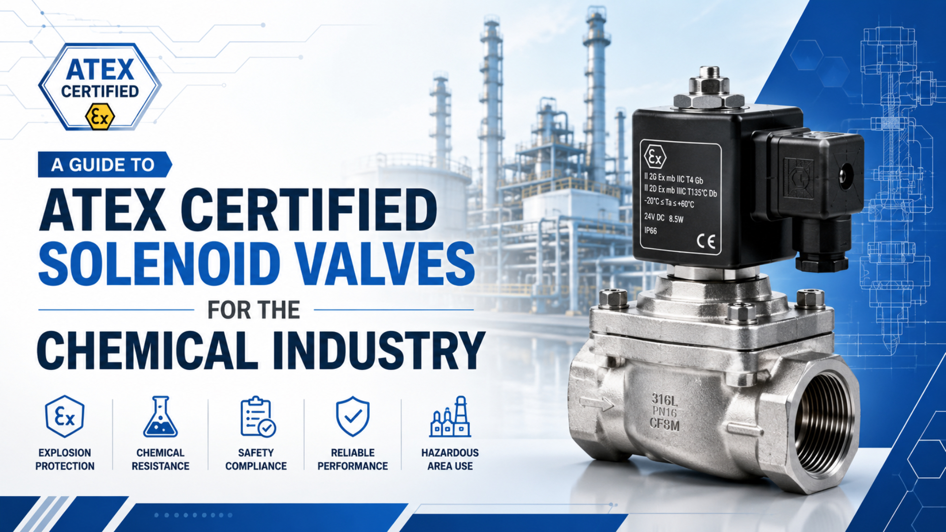
An ATEX solenoid valve for a chemical plant must match the classified area, explosive-atmosphere type, equipment category, Equipment Protection Level, gas or dust group, temperature marking, ambient range, electrical installation, process medium, and valve duty. A generic “explosion-proof coil” description is not enough.
The evidence matters as much as the hardware. Before approval, obtain the exact product marking, EU Declaration of Conformity, certificate and schedule where applicable, installation instructions, special conditions of use, and proof that the quoted coil, valve body, cable entry, connector, seal package, and accessories form an allowed configuration.
ATEX equipment conformity concerns products placed on the European Union market under Directive 2014/34/EU. Workplace explosion protection concerns the employer’s assessment, zone classification, controls, and explosion protection document under Directive 1999/92/EC. The equipment supplier and plant operator therefore have different but connected responsibilities.
Key Takeaways
- Classify the hazardous area before selecting the valve.
- Match Zone, Category, EPL, group, and temperature marking.
- Verify the complete valve configuration, not only the coil.
- Check chemical compatibility separately from explosion protection.
- Follow certified installation, inspection, and repair conditions.
What Do ATEX, IECEx, and IEC 60079 Mean?
Directive 2014/34/EU has applied since 20 April 2016 and covers equipment and protective systems intended for potentially explosive atmospheres (European Commission, retrieved July 11, 2026). It establishes EU product requirements and conformity-assessment routes rather than one valve-design standard.
ATEX is commonly used as shorthand for two separate EU legal frameworks:
- Directive 2014/34/EU, often called the ATEX product directive, applies to manufacturers and other economic operators placing covered products on the EU market.
- Directive 1999/92/EC, sometimes called the workplace ATEX directive, requires employers to assess explosion risks, classify hazardous places, apply minimum protections, and maintain an explosion protection document.
IEC 60079 is a family of technical standards for explosive atmospheres. Different parts address general equipment requirements, protection concepts, gas and dust area classification, electrical installation, inspection, maintenance, repair, and other specialized subjects.
IECEx is an international conformity-assessment system based on IEC standards. It can provide an IECEx Certificate of Conformity and associated test and quality records. It does not replace the legal obligations of ATEX when equipment is placed on the EU market, and ATEX documentation does not automatically satisfy every non-EU jurisdiction.
Ask which market and installation rules apply before treating “ATEX/IECEx available” as a complete specification. A chemical plant may also be subject to national electrical codes, fire regulations, pressure-equipment rules, functional-safety requirements, and site engineering standards.
Start with Hazardous-Area Classification
Directive 1999/92/EC requires the employer to classify places where explosive atmospheres may occur and keep the explosion protection document current (EUR-Lex, retrieved July 11, 2026). A valve supplier should use that classification as an input, not create arbitrary zone distances from a product catalog.
For gases, vapours, and mists:
| Workplace zone | Presence of explosive atmosphere | Typical ATEX equipment category | Typical EPL |
|---|---|---|---|
| Zone 0 | Continuously, for long periods, or frequently | 1G | Ga |
| Zone 1 | Likely to occur occasionally in normal operation | 2G or 1G | Gb or Ga |
| Zone 2 | Not likely in normal operation, or only briefly | 3G, 2G, or 1G | Gc, Gb, or Ga |
For combustible dust:
| Workplace zone | Presence of explosive atmosphere | Typical ATEX equipment category | Typical EPL |
|---|---|---|---|
| Zone 20 | Continuously, for long periods, or frequently | 1D | Da |
| Zone 21 | Likely to occur occasionally in normal operation | 2D or 1D | Db or Da |
| Zone 22 | Not likely in normal operation, or only briefly | 3D, 2D, or 1D | Dc, Db, or Da |
These mappings are selection starting points, not a substitute for the site classification report. IEC 60079-10-1:2020 covers classification where flammable gas or vapour hazards may arise and supports the design, operation, and maintenance of hazardous-area equipment (IEC, 2020; retrieved July 11, 2026).
Zone extent depends on the release source, release rate, ventilation, material properties, process pressure, temperature, openings, pits, and enclosure geometry. A statement such as “Zone 1 extends three metres” is not transferable between plants.
For a solenoid valve RFQ, provide the zone drawing, gas or dust data, ambient range, indoor or outdoor exposure, ventilation assumptions, and any equipment-location restrictions. Without those inputs, a supplier can confirm available markings but cannot confirm suitability for the installation.
How Do You Read an ATEX Valve Marking?
Directive 2014/34/EU requires clear product marking tied to intended use, while the manufacturer’s instructions must supply the information needed for safe use (EUR-Lex, 2014; retrieved July 11, 2026). Read the whole marking string rather than searching only for the Ex symbol.
An illustrative gas-atmosphere marking is II 2G Ex db IIC T4 Gb:
- II: equipment group for non-mining surface industries
- 2G: ATEX Category 2 for gas, vapour, or mist atmospheres
- Ex: explosion-protected equipment
- db: flameproof protection level notation
- IIC: gas group covering the most demanding group within the IIA/IIB/IIC sequence
- T4: maximum surface-temperature class under the defined conditions
- Gb: Equipment Protection Level for gas atmospheres
A dust marking uses different information, for example a dust group and maximum surface temperature in degrees Celsius rather than relying on a gas T-class alone. Depending on the product, it may also state ingress protection.
The exact marking must be copied from the product nameplate or controlled certificate documentation. Never construct a marking from sales language. Also confirm:
- Certificate number and any suffix such as X or U
- Notified-body identification where required
- Ambient-temperature limits
- Electrical voltage, current, and power
- Duty cycle
- Ingress protection
- Process-temperature restrictions
- Cable-entry and blanking-element requirements
- Special installation or use conditions
An X certificate suffix indicates that special conditions for safe use apply. Those conditions are mandatory inputs to the installation. A U suffix is associated with an Ex component certificate; a component is not necessarily approved for independent installation as complete equipment.
How Do Gas Group and Temperature Affect Selection?
Directive 2014/34/EU requires equipment to remain safe within the operating limits established by the manufacturer, including environmental effects, temperature, contamination, vibration, and aggressive substances (EUR-Lex, retrieved July 11, 2026). The nameplate range must cover the real chemical-plant conditions.
For gas atmospheres, identify the substance and required group:
- IIA covers less demanding representative gases within the group system.
- IIB requires equipment suitable for a more demanding group.
- IIC is the most demanding of IIA, IIB, and IIC.
Equipment marked IIC can generally cover IIB and IIA from the explosion-group perspective, but chemical compatibility, temperature, pressure, and installation conditions still need separate confirmation.
Temperature class limits the equipment’s maximum surface temperature under its certified conditions. The selected class must be suitable for the ignition characteristics of the explosive atmosphere and any safety margin required by the applicable design method.
Do not confuse maximum process-fluid temperature, ambient temperature, coil temperature rise, maximum equipment surface temperature, gas auto-ignition temperature, and dust ignition characteristics.
For combustible dust, assess dust group, layer accumulation, housekeeping, enclosure protection, and permitted surface temperature. A valve acceptable for a gas Zone 1 installation is not automatically acceptable for a dust Zone 21 installation.
Which Protection Concept Fits a Solenoid Valve?
The current IEC 60079 series includes separate standards for flameproof enclosure, increased safety, intrinsic safety, encapsulation, installation, inspection, and repair (IEC, retrieved July 11, 2026). Select the protection concept from the certificate and system design, not from a one-line preference chart.
Flameproof protection
A flameproof enclosure is designed so an internal ignition does not transmit through the certified flame paths to the external explosive atmosphere. Installation must preserve the certified enclosure, threads, joints, cable entries, blanking elements, fasteners, and temperature conditions.
Do not machine, repaint critical joints, substitute bolts, or open an energized enclosure in a hazardous atmosphere unless the instructions and site procedure explicitly allow the work.
Intrinsic safety
An intrinsically safe circuit limits electrical and thermal energy so ignition is prevented under the fault conditions addressed by its protection level. The assessment covers the complete loop, not only the coil.
Check the solenoid’s entity parameters against the associated apparatus or galvanic isolator. Include cable capacitance and inductance, grounding concept, segregation, connector arrangement, and control-system output. A normal low-wattage coil is not intrinsically safe merely because it consumes little power.
Increased safety
Increased-safety protection applies additional measures against arcs, sparks, and excessive temperatures in equipment where the protection concept permits it. The exact solenoid construction and marking determine whether and how it is used. “Non-sparking” sales language is not proof of Ex e suitability.
Encapsulation
Encapsulation protects ignition-capable parts within a certified compound system. Temperature, curing, void control, lead entry, mechanical protection, and the approved assembly remain part of the certified design. A damaged or modified encapsulated coil should not receive an improvised field repair.
Some solenoid assemblies combine protection concepts. Record the complete marking exactly and follow the certificate schedule. Do not replace it with a generic label such as “explosion proof.”
Is the Complete Solenoid Valve an Approved Configuration?
Directive 2014/34/EU defines equipment, components, safety devices, and intended use separately, making the certified product boundary important (EUR-Lex, 2014; retrieved July 11, 2026). Confirm whether the certificate covers the complete valve assembly, the coil, or another component.
| Item | What to verify |
|---|---|
| Valve model | Exact family, port size, function, pressure range, and revision |
| Coil model | Voltage, frequency, power, duty, ambient range, and Ex marking |
| Connector or terminal box | Approved type and orientation |
| Cable gland | Protection concept, thread, cable diameter, group, temperature, and IP |
| Blanking plug | Certified type for unused entries |
| Valve body | Material, port thread, process medium, and pressure |
| Seals | Compound and chemical compatibility |
| Manual override | Whether fitted, permitted, lockable, or restricted |
| Accessories | Silencers, controls, manifolds, and mounting kits allowed by the instructions |
Common documentation failures include a certificate for a similarly named family, a coil certificate with no evidence for the assembled valve, a quotation omitting special conditions, and a cable gland whose marking does not match the enclosure.
Where a valve controls compressed air rather than the hazardous process fluid, external atmosphere compatibility still matters. Corrosive vapour can attack fasteners, cable entries, nameplates, coatings, and electrical seals even when the internal medium is clean air.
For basic valve architecture, use How Do Pneumatic Solenoid Valves Work to Control Compressed Air Flow?. The ATEX assessment comes after the required valve function is understood.
Chemical Compatibility Remains a Separate Check
Directive 2014/34/EU requires equipment parts to withstand foreseeable aggressive substances where relevant to intended use (EUR-Lex, retrieved July 11, 2026). An acceptable Ex marking does not prove compatibility with every solvent, acid, alkali, cleaning agent, or process gas.
Identify whether the valve handles clean instrument air, inert gas, fuel gas, solvent vapour, liquid chemical, corrosive or toxic medium, vacuum, or contaminated exhaust.
Then verify body, seat, diaphragm, seals, springs, shading rings, lubricant, and thread sealant. Confirm pressure, differential pressure, flow direction, minimum pilot pressure, leakage requirement, viscosity, media temperature, and fail position.
A stainless-steel body may improve corrosion resistance but does not prove that the seals or coil enclosure suit the environment. Conversely, a brass valve may be acceptable for one clean-air control duty but unsuitable for an aggressive external atmosphere or process medium.
Changing a seal compound, connector, cable gland, coil, manual override, or coating can move the assembly outside its assessed configuration. Obtain written manufacturer confirmation before substitutions.
For functional selection, compare direct-acting and pilot-operated solenoid valves. Pilot-operated valves can require a minimum pressure differential that affects safe process behavior even when the Ex marking is correct.
If switching time affects the process hazard analysis, use the separate guide to measuring pneumatic solenoid-valve response time. ATEX marking controls ignition suitability, not the process shutdown time.
Installation Requirements
IEC 60079-14:2024 is the current installation-design and erection part listed in the IEC 60079 series, while IEC 60079-17:2023 covers inspection and maintenance of electrical installations in explosive atmospheres (IEC, retrieved July 11, 2026). Use the editions adopted by the project and jurisdiction.
Before energization:
- Compare the nameplate with the hazardous-area equipment schedule.
- Confirm Zone, Category, EPL, group, temperature marking, and ambient range.
- Read the certificate, schedule, instructions, and special conditions.
- Verify the approved cable gland, thread engagement, cable diameter, and blanking plugs.
- Complete earthing and bonding according to the certified design.
- Confirm enclosure seals and IP features are undamaged.
- Check coil voltage, power, duty cycle, and control output.
- Confirm valve pressure, media, flow direction, and pilot requirements.
- Protect the assembly from impact, vibration, heat, corrosion, and unauthorized adjustment.
- Record the installed model, identifier, certificate, location, and inspection result.
There is no universal EU-wide job title called an “ATEX-certified installer” that replaces competency assessment. Use personnel competent for the protection concept, equipment, installation standard, national rules, and site procedure.
Do not assume ordinary conduit fittings, cable glands, reducers, adapters, or plugs preserve the protection concept. Every entry component must match the enclosure certificate, thread form, cable construction, zone, group, and temperature conditions.
Where the solenoid belongs to a safety-related pneumatic circuit, evaluate functional safety separately. The safety exhaust valve integration guide explains why explosion protection and machine safety performance are different approvals.
Inspection, Maintenance, and Repair
Directive 1999/92/EC requires the explosion protection document to be prepared and kept up to date, while IEC 60079-17:2023 provides the technical framework for inspection and maintenance (EUR-Lex, retrieved July 11, 2026). Inspection intervals must reflect the installation rather than a generic three-month schedule.
Develop the program from the protection concept, manufacturer instructions, environmental severity, corrosion, dust, moisture, vibration, operating frequency, accessibility, previous findings, consequence of failure, national requirements, and site standards.
Inspection should verify legible marking, enclosure integrity, cable entries, fasteners, seals, bonding, corrosion, temperature exposure, unauthorized modifications, and valve function. Functional testing alone cannot reveal damaged flame paths or an incorrect cable gland.
Repairs that affect explosion protection require controlled methods and competent personnel. IEC 60079-19:2025 is included in the current IEC series for repair, overhaul, and reclamation. A field repair should not alter a flameproof joint, encapsulated coil, certified winding, terminal arrangement, or other protected feature without an approved basis.
If the exact certified replacement is unavailable, stop and reassess. Similar voltage, port size, or appearance does not establish equivalent explosion protection.
For the surrounding non-safety pneumatic architecture, review how to build a reliable modular valve circuit without treating ordinary manifold components as automatically suitable for the classified area.
ATEX Solenoid Valve RFQ Checklist
The European Commission states that CE marking can be applied only after the required product testing and conformity-assessment procedure has been performed (European Commission, retrieved July 11, 2026). Ask for controlled evidence before accepting a quotation.
Provide the installation country, regulatory scheme, Zone, Category, EPL, gas or dust group, temperature requirement, ambient and process temperatures, external exposure, electrical supply, valve function, ports, flow requirement, pressure range, process medium, fail position, cable-entry requirements, and documentation language.
Request:
- Exact model code and full marking string
- EU Declaration of Conformity
- Certificate and schedule where applicable
- Current installation and maintenance instructions
- Special conditions for safe use
- Product drawing and nameplate image
- Permitted accessories and replacement parts
- IECEx certificate if required
- Written chemical-compatibility confirmation
Calculator tools: none. ATEX conformity, area classification, ignition risk, and chemical compatibility cannot be established with general pneumatic calculators.
Frequently Asked Questions
Is ATEX the same as IECEx?
No. ATEX is EU legislation governing products and workplaces in potentially explosive atmospheres. IECEx is an international conformity-assessment system based on IEC standards. A project may request both, but acceptance depends on where the equipment will be placed on the market and installed.
Can an existing standard solenoid valve be retrofitted with an ATEX coil?
Not automatically. The certified product boundary may cover only a specific coil, valve family, connector, gland, and assembly method. Adding an Ex coil to an arbitrary valve does not establish ATEX conformity. Obtain manufacturer documentation for the exact completed configuration.
Does an IIC valve work in an IIA area?
From the gas-group perspective, IIC is more demanding than IIB and IIA. The valve must still match Category, EPL, temperature class, ambient range, protection concept, process conditions, chemical compatibility, and certificate conditions.
How often should an ATEX solenoid valve be inspected?
Use the applicable IEC 60079-17 inspection approach, manufacturer instructions, environmental severity, equipment history, site explosion protection document, and national requirements. A universal three-month, six-month, or annual interval cannot be assigned safely to every installation.
Does an IP66 rating make a solenoid valve explosion proof?
No. IP66 describes protection against dust ingress and powerful water jets under the relevant enclosure test. Explosion protection requires the applicable Ex design, marking, conformity evidence, and installation. IP performance may support the certified design but does not replace it.
Conclusion
Selecting an ATEX solenoid valve for a chemical plant is a document-driven engineering task. Begin with the site zone classification and explosive substance. Match Category, EPL, group, temperature marking, protection concept, ambient range, and installation conditions. Then verify the complete model and certificate boundary.
Explosion protection is only one acceptance dimension. The valve must also meet the process function, pressure, differential pressure, flow, failure position, material compatibility, corrosion exposure, and maintenance strategy. When the marking, certificate, quotation, and delivered nameplate agree, the review is auditable. When they do not, the valve should not enter service.
Sources
- European Commission. Equipment for potentially explosive atmospheres. Retrieved July 11, 2026.
- European Commission. Harmonised standards for ATEX equipment. Retrieved July 11, 2026.
- EUR-Lex. Directive 2014/34/EU. Retrieved July 11, 2026.
- EUR-Lex. Directive 1999/92/EC. Retrieved July 11, 2026.
- International Electrotechnical Commission. IEC 60079-10-1:2020. Retrieved July 11, 2026.
- International Electrotechnical Commission. IEC 60079 Series. Retrieved July 11, 2026.