

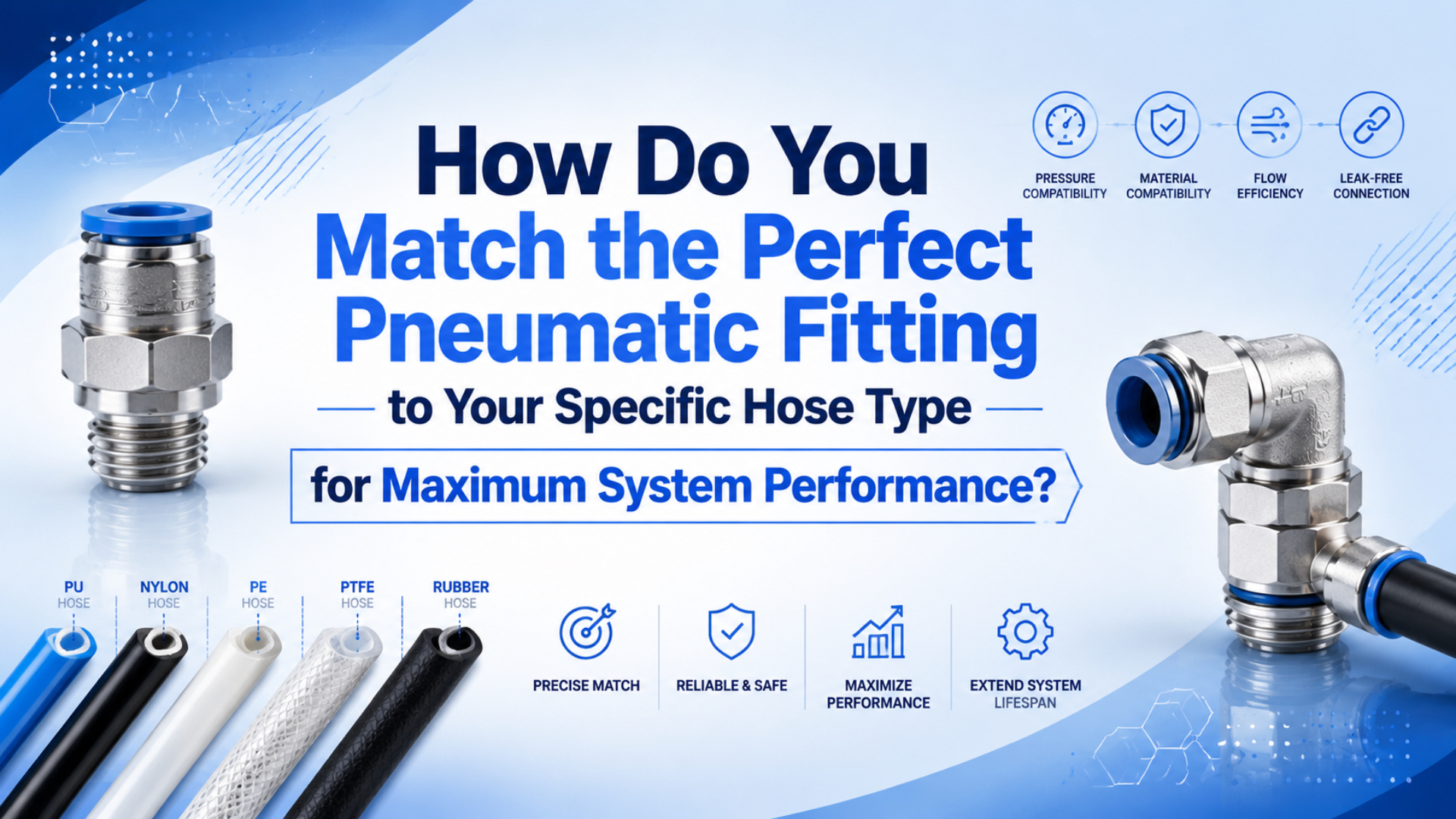
Pneumatic fitting hose compatibility means matching the fitting to the exact tube or hose data, not just its marked size or material name. The parts must agree on connection type, controlled diameter, wall, hardness, pressure, heat, media, motion, and install method. Hand-fitting proves little. The tube can still fail.
A push-in fitting is an OD-gripping tube connector. A hose-barb connection is an interface that grips flexible hose by its inside diameter and uses the specified clamp or crimp. A compression fitting is a system whose nut, ferrule, insert, body, and tubing must use one approved make-up method.
Key Takeaways
- ISO 14743:2020 covers complete push-in assemblies for thermoplastic tube from 3 to 16 mm OD.
- Match the exact fitting series, tube material, dimensions, pressure, temperature, and media.
- Working pressure governs selection.
- Follow the manufacturer’s insertion, tube-support, torque, clamp, crimp, inspection, and reconnection instructions for the exact parts being assembled.
Procurement needs a complete interface. The approved unit includes the fitting catalog number, tube or hose specification, installation method, and acceptance test. Recording that combination prevents maintenance teams from substituting a visually similar tube whose hardness, wall thickness, or tolerance changes the connection.
What Must Match Between a Pneumatic Fitting and Hose?
ISO 14743:2020 covers complete push-in connector assemblies for thermoplastic tube with outside diameters from 3 to 16 mm, including inch dimensions, and establishes uniform assembly tests (ISO, ISO 14743:2020, 2020). Approve the complete assembly under its real operating conditions, not a material stereotype.
Size alone is not enough.
Check these seven interfaces before approving the connection:
- Connection method: push-in, compression, barb and clamp, crimp, or quick-disconnect.
- Controlled dimension: tube OD for most push-in fittings; hose ID for many barbs; and OD, ID, wall thickness, ferrule geometry, or an internal support for compression systems.
- Material and hardness: PU, PA, PE, PVC, fluoropolymer, rubber compound, or another manufacturer-approved material.
- Pressure and temperature: normal, maximum, surge, vacuum, ambient, and media conditions.
- Fluid compatibility: compressed air quality, water, oil, cleaning chemicals, or process media.
- Mechanical duty: vibration, bending, tensile load, repeated disconnection, and branch weight.
- Port interface: NPT, BSPT/R, BSPP/G, metric, or another thread and sealing method.
Parker’s current push-to-connect catalog illustrates why the series matters. One family lists polyethylene, polypropylene, semi-rigid nylon, and 94 Shore A polyurethane as compatible, while other families list different materials and ratings (Parker, Push-to-Connect Fittings, accessed 2026). Material name alone does not approve the combination.
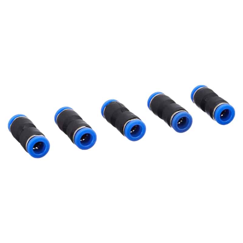
A straight union links approved tubes. Similar appearance does not prove that two fitting series accept the same hardness, manufacturing tolerance, surface condition, duty cycle, or pressure-temperature range.
Which Fitting Types Suit PU, Nylon, PE, PVC, and Rubber?
SMC’s KQ2 one-touch family lists five applicable thermoplastic categories: FEP, PFA, nylon, soft nylon, and polyurethane, subject to its product conditions (SMC, KQ2 One-touch Fittings, accessed 2026). The correct choice comes from the exact product datasheet; material stereotypes are only a shortlist, never final approval.
Parts that look alike can differ.
| Tube or hose starting point | Common connection shortlist | What must be confirmed |
|---|---|---|
| Polyurethane tube | Manufacturer-approved push-in; selected compression systems | Shore hardness, OD tolerance, wall thickness, temperature derating, tube support |
| Nylon or polyamide tube | Push-in or compression system approved for that PA grade | Rigid or soft nylon, moisture and temperature effects, bend radius, OD and ID |
| Polyethylene tube | Compatible push-in or purpose-designed compression fitting | Density/grade, creep, pressure-temperature curve, chemical exposure |
| PVC or soft vinyl hose | Hose barb, clamp, or a listed compression system | Hose ID, wall softness, plasticizer compatibility, clamp or ferrule range |
| Rubber hose | Barb and clamp, crimped assembly, or listed reusable coupling | Rubber compound, reinforcement, hose ID/OD, cover, clamp or crimp specification |
| FEP or PFA tube | Product-specific push-in or compression connection | Permeation, cold flow, temperature, surface condition, approved insert or support |
Check the part number.
When comparing push-in fitting families, treat each tube-material list and pressure-temperature table as series-specific.
These are screening directions, not universal pairings. Parker’s brass hose-barb product 1295HB-6-6, for example, is listed for GPH and rubber hose, has a 3/8-inch hose interface, and carries a 150 psi maximum rating for that catalog configuration (Parker, 1295HB Brass Hose Barb Fitting, accessed 2026). That does not make every barb suitable for every rubber hose. Likewise, “PU” is not one dimensionally identical material. One push-in catalog may approve 95A tube but require a support for a softer construction; another compression system may work only with its own ferrule and insert. Ask for the acceptable tube series or a dimensional and material specification, not merely the letters PU.
Harsh environments add body and seal checks. The stainless steel pneumatic fittings guide covers 304/316L selection, seal compounds, cleaning exposure, and mixed-metal joints.
How Do OD, ID, Hardness, and Wall Thickness Change the Choice?
ASTM D2240:2021 defines 12 durometer types for indentation-hardness testing and warns that no simple relationship exists between hardness readings and a fundamental material property (ASTM, D2240-15(2021), 2021). Hardness is one compatibility input; it cannot replace the fitting maker’s approved tube material, OD tolerance, or wall specification.
Do not mix those dimensions.
Outside diameter controls most push-in connections
The collet or gripping ring engages the tube OD, while an internal seal closes around the same surface. Nominally similar tube can leak or pull out if it is undersize, oval, scratched, swollen, or too soft for the retention design. Metric and inch sizes are especially easy to confuse: 6 mm is not 1/4 inch, and 8 mm is not 5/16 inch. Measure with the method and tolerance used by the tube supplier. Do not “fix” an undersize tube with sealant or extra insertion force.
Inside diameter controls many barbed connections and the airflow path
Hose-barb fittings are normally selected around hose ID, barb geometry, material softness, reinforcement, and the specified clamp or crimp system. The hose can slip. Inside diameter also affects restriction. Reducing the passage through a small fitting can create local pressure loss even if the connection does not leak.
When airflow is the unresolved variable, estimate the required passage with the Tube ID Calculator and then verify the selected fitting’s published bore or flow coefficient. The separate Cv sizing guide explains the sizing variable, while the fitting flow and efficiency guide covers its system-level energy effect.
Wall thickness affects support and compression
Wall construction differs. Thin or soft walls can collapse under a ferrule, distort under a push-in seal, or require an internal support. Thicker walls may improve stiffness but reduce flow area. Use only the insert, ferrule, sleeve, clamp, or crimp tooling identified for that hose-and-fitting family.
In our experience, recurring pull-outs are often interface-control problems rather than defective fitting bodies. Useful checks are mundane: confirm metric versus inch OD, cut back a scratched end, verify full insertion, remove side load, and compare the tube marking with the approved specification. Those observations are more diagnostic than changing fitting brands immediately.
Pressure, Temperature, and Media Define the Real Rating
Parker’s general selection guide requires hose working pressure to equal or exceed maximum system pressure and explicitly says not to substitute burst pressure for working pressure (Parker, Fittings & Tubing Catalog 0700P, accessed 2026). Rate the installed connection by its lowest component limit at the real temperature and media condition.
The pneumatic working-pressure guide explains why a regulator setpoint, dynamic cylinder-port pressure, and component rating are different values.
Working pressure controls.
Use this hierarchy:
- Maximum system pressure, including credible surge, trapped pressure, and the operating states that create them.
- The tube or hose working-pressure curve at the actual temperature.
- Fitting body, seal, collet, ferrule, clamp, or crimp rating.
- Port, valve, manifold, and downstream component limits.
- Vacuum duty.
- Compatibility of every wetted material with compressed air, compressor oil, water, cleaning chemicals, and any process media that can reach the connection.
SMC’s KQ2 catalog, for example, publishes an operating range from -100 kPa to 1 MPa and a 3 MPa proof pressure under stated conditions (SMC, KQ2 One-touch Fittings, accessed 2026). Proof pressure is not permission to operate continuously at 3 MPa. Its working limit and conditions control normal use.
Temperature changes retention. Heat can change fit. Thermoplastics soften, stiffen, creep, or change dimensions; elastomer seals can lose compatibility; hose reinforcement and clamps can relax. Use the combined pressure-temperature rating for the exact tube and fitting. Don’t combine the pressure limit from one catalog with the temperature limit from another.
Media matters. Compressed air may contain water, compressor oil, cleaning chemicals, or process contamination. Check the tube, seal, body, thread sealant, lubricant, and clamp separately. For air cleanliness requirements upstream of the connection, use the ISO 8573-1 compressed-air quality guide.
Installation Rules by Connection Type
Parker rates one listed rubber-hose barb configuration to 150 psi, while its push-to-connect catalog includes families rated up to 300 psi depending on tubing (Parker, Brass Hose Barb Fittings, accessed 2026). Those different interfaces need different installation rules; one generic torque or “extra half-turn” cannot cover them.
Do not guess.
Push-in fittings
- Isolate the supply and exhaust every volume that can retain hazardous pneumatic energy.
- Confirm the approved tube material and exact OD.
- Cut square with a tube cutter; reject crushed, oval, deeply scratched, heat-damaged, or contaminated ends before they reach the seal.
- Insert fully.
- Apply the specified pull check without twisting the tube.
- Support elbows, tees, vertical drops, and vibrating runs so their weight and bending moment do not load the collet.
- Repressurize under the site’s controlled procedure, observe the maximum repeatable demand state, and inspect for leakage or tube movement.
For a deeper leak-focused procedure after compatibility is confirmed, use the push-in fitting installation guide.
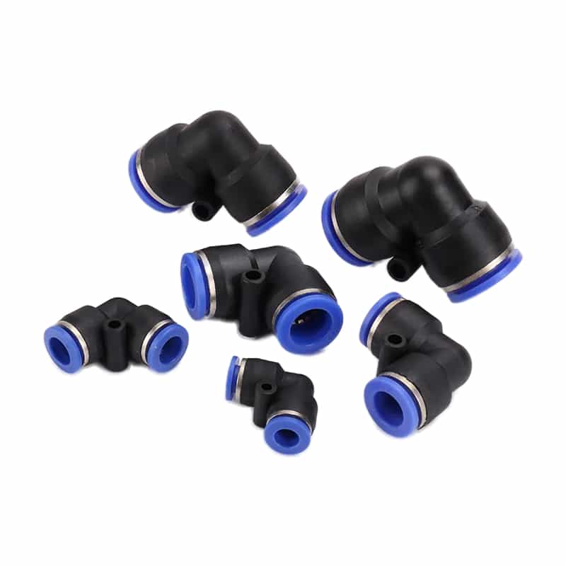
An elbow can improve routing, but the tube still needs the manufacturer’s minimum bend radius and support. Do not use the fitting as a structural bracket.
Compression fittings
Keep one documented system. Follow the exact make-up instruction, including any required number of turns or torque. Generic values are unsafe because ferrule design, tube material, thread, size, and reuse rules differ. Mark the starting position when the manufacturer uses turns-from-finger-tight as its method.
Hose barbs and clamps
Match the interface. Place the clamp where the fitting manufacturer specifies, not at the hose edge. Undersize clamps can cut or deform the hose; oversize clamps can bottom before generating the required grip. Reinforced hose may require a crimped assembly rather than a workshop clamp.
Threaded ports
Identify the thread. Tapered and parallel forms use different sealing mechanisms, so apply only the permitted sealant and manufacturer torque. Keep tape fragments, excess liquid sealant, and metal debris out of the airflow path.
Before removing or installing any connection during covered servicing, follow the site’s energy-control procedure. OSHA 29 CFR 1910.147 includes pneumatic energy and requires hazardous stored or residual energy to be relieved, disconnected, restrained, or otherwise rendered safe (OSHA, Control of Hazardous Energy, accessed 2026).
How Do You Verify a Connection Before Production?
ISO 14743:2020 is a 30-page standard intended to establish uniform tests for complete push-in assemblies, not to create one field proof pressure for every installation (ISO, ISO 14743:2020, 2020). Define the production acceptance test from the exact product ratings, circuit risk, and machine procedure.
Flow must also be checked.
Idle leakage is only one state; test the full cycle.
Use a controlled verification record:
| Check | Acceptance evidence |
|---|---|
| Identity | Fitting catalog number, tube or hose part number, size, material, lot where required |
| Preparation | Square cut, clean surface, correct ferrule/insert/clamp, no visible damage |
| Assembly | Published insertion depth, make-up method, crimp dimension, or clamp position |
| Routing | Bend radius, support spacing, no tensile or side load at the fitting |
| Pressure | Test pressure and hold time approved for the complete circuit |
| Leakage | No unacceptable leakage using the site’s permitted detection method |
| Retention | No tube or hose movement under the specified functional test |
| Function | Required actuator speed, pressure recovery, and cycle behavior achieved |
Test within the lowest component rating. If a higher proof test is required by a machine standard or customer specification, confirm that every component and the procedure explicitly allow it.
A strong acceptance record joins mechanical and pneumatic evidence. “No bubbles at idle” proves only one state. Add the maximum repeatable demand condition, because a connection can remain leak-tight yet restrict flow enough to slow an actuator. See the pressure-drop troubleshooting guide to separate connection restriction from upstream supply loss.
Diagnosing Why a Hose Pulls Out, Leaks, or Restricts Flow
Parker publishes push-to-connect families up to 300 psi depending on tubing, which makes “the fitting is rated to 300 psi” incomplete without the approved tube and size (Parker, Push-to-Connect Fittings, accessed 2026). Diagnose the interface and operating state before replacing the fitting body.
Damage changes the answer; leaks waste air.
| Symptom | Likely interface checks | Corrective direction |
|---|---|---|
| Tube pulls out | Wrong OD, soft or unapproved tube, incomplete insertion, damaged collet, side load | Restore the approved tube/fitting combination and routing |
| Leakage at tube | Scratched or oval OD, cut not square, contaminated seal, swollen tube | Cut back or replace tube; inspect seal and insertion depth |
| Leakage at thread | Wrong thread form, damaged port, incorrect sealant, poor alignment | Identify thread and reinstall to exact instructions |
| Hose splits near barb | Barb oversize, clamp damage, tight bend, aging or incompatible media | Replace damaged hose and correct barb, clamp, support, or material |
| Slow actuator | Small ID, restrictive elbow or reducer, long line, high demand | Measure dynamic pressure and review bore, flow, and line length |
| Failure after heat or washdown | Temperature derating, tube creep, seal or chemical incompatibility | Revalidate the full pressure-temperature-media combination |
Inspect every reused tube end. Collet marks, longitudinal scratches, swelling, hardening, flattening, or loss of roundness can change sealing and retention. Follow the fitting maker’s reconnection rules and cut back only when adequate tube length and routing remain.
What Are the FAQs About Matching Pneumatic Fittings?
ISO 14743 covers tube ODs from 3 to 16 mm, while Parker’s cited barb example is specified by a 3/8-inch hose interface; those two systems control different dimensions (ISO, 2020; Parker, accessed 2026). Identify whether OD, ID, or a proprietary assembly controls the match.
Can I use the same push-in fitting with PU and nylon tube?
Only when the exact fitting series lists both materials and the selected sizes meet its conditions. Check rigid versus soft nylon, PU hardness, OD tolerance, wall thickness, temperature, and whether a tube support is required. Similar OD proves nothing.
Is 6 mm pneumatic tube interchangeable with 1/4-inch tube?
No. NIST defines one inch as exactly 25.4 mm, making one quarter inch 6.35 mm rather than 6 mm (NIST, SI Units: Length, accessed 2026). Wrong-size tube may enter the connector but fail its sealing or retention limits. Match the catalog dimension.
Should the fitting rating exceed working pressure by 25%?
There is no universal 25% rule for every pneumatic connection. Parker instead directs users to select published hose working pressure at or above maximum system pressure and to account for surge and temperature (Parker, Fittings & Tubing Catalog 0700P, accessed 2026). Additional margin must come from the machine standard or risk assessment.
Can I select a hose from burst pressure?
No. Parker’s selection guide instructs users to compare maximum system pressure with published maximum recommended working pressure and not to substitute burst pressure. Burst data may support product qualification, but it is not the normal operating limit.
How tight should a pneumatic compression fitting be?
Use the exact manufacturer’s make-up instruction for the fitting family, tube material, and size. Some systems use torque; others specify turns from finger-tight or a gap inspection. Generic tables fail.
Why does a correctly sized push-in connection still leak?
Size is only one condition. Check tube material, hardness, OD tolerance, surface scratches, ovality, insertion depth, seal contamination, temperature change, side load, and whether the end was previously gripped. Replace damaged tube and fitting parts according to the manufacturer’s instructions.
Specify the exact parts, respect the lowest rating, install them by the documented method, and verify both leakage and machine function. That is faster than investigating recurring pull-outs after production starts.
About the author: Jason Tan is a pneumatic manufacturing engineer. A fact-check review compared this guide with the cited standards and current manufacturer literature retrieved on July 14, 2026. For an application-specific review, contact Bepto Pneumatic with the fitting series, tube or hose specification, pressure, temperature, media, and installation conditions.
External technical references and retrieval dates
ISO 14743:2020, Push-in Connectors for Thermoplastic Tubes. Retrieved 2026-07-14.
Parker, Push-to-Connect Fittings. Retrieved 2026-07-14.
Parker, Fittings & Tubing Catalog 0700P. Retrieved 2026-07-14.
Parker, 1295HB Brass Hose Barb Fitting. Retrieved 2026-07-14.
SMC, KQ2 One-touch Fittings. Retrieved 2026-07-14.
ASTM D2240-15(2021), Rubber Property Durometer Hardness. Retrieved 2026-07-14.
OSHA 29 CFR 1910.147, Control of Hazardous Energy. Retrieved 2026-07-14.
NIST, SI Units: Length. Retrieved 2026-07-14.