

ISO 8573-1 compressed air quality management replaces “clean dry air” with measurable limits for particles, water, and oil at named locations. The standard becomes useful when each requirement has an owner, sampling point, test method, acceptance record, and response plan. A filter model alone is not an air-quality program.
The management task starts at the point of use. Air can meet a target after the compressor-room dryer and fail at a distant machine because of wet pipework, corroded drops, saturated filters, oil vapor, or maintenance debris. Treat the class code as a performance contract for a stated location and operating condition.
Key Takeaways
- ISO 8573-1 uses three separate purity classifications for particles, water, and oil.
- Class 0 has no universal numeric limit; it must be specified more strictly than Class 1.
- Validation requires the relevant ISO 8573 test methods, representative sampling, and records from the promised point of use.
ISO 8573-1 air-quality specification is a written particles:water:oil target tied to a defined compressed-air location.
Sampling point is the physical connection where air is taken for a test under recorded pressure, temperature, flow, and operating conditions.
Acceptance boundary is the location and condition where the plant, supplier, or process owner agrees that the air-quality requirement must be met.
What Does ISO 8573-1 Control in a Plant Program?
ISO lists ISO 8573-1:2010 as a 9-page standard covering three principal contaminant groups: particles, water, and oil. It applies independently of where air is specified or measured, and the 2010 edition remains current while a revision is planned (ISO 8573-1, 2010).
That scope changes the plant conversation. ISO 8573-1 does not certify a compressor, filter, dryer, or entire factory by itself. It provides classifications that users can apply to a stated point in a compressed-air system. The class can describe a requirement, equipment outlet performance, or a measured result, but those are different claims.
The shorthand is normally written in the order particles:water:oil. Each position comes from a separate table. This is why phrases such as “nine purity classes” or a three-digit code using Class 9 in every position create trouble. The available rows and limits differ by contaminant.
| Class-code position | Main property | What the plant must define |
|---|---|---|
| First | solid particles | count by particle-size range or mass concentration, plus test method |
| Second | water | pressure dew point or liquid-water concentration, plus operating condition |
| Third | total oil | liquid oil, aerosol, and vapor as required by the selected class and method |
ISO also identifies gaseous and microbiological contamination. Those risks may matter in process air even when the familiar three-position code is the main purchasing and maintenance shorthand.
For a broader introduction to the standard and treatment hardware, use the existing guide to ISO air-quality standards for pneumatic systems. This article focuses on how a plant governs and verifies the requirement after the class has been selected.
A class code without a location is an incomplete control. The same plant can have one result after the dryer, another at the end of the distribution header, and a third at the machine inlet. Quality management begins when the drawing, test report, and maintenance record name the same boundary.
How Should Each Point-of-Use Requirement Be Written?
Parker’s Class 1:2:1 example sets particle limits of 20,000, 400, and 10 per cubic meter across three size bands, water at -40°C pressure dew point, and total oil at 0.01 mg/m³ (Parker, 2026). A complete requirement also names location and operating condition.
The numbers are useful only when the note also names where and when they apply. A production drawing should not say merely ISO 8573-1 Class 1:2:1. Add the sampling point, normal pressure, expected flow or production state, and whether the target is a design requirement or an acceptance result.
Compressed air at packaging manifold inlet:
ISO 8573-1:2010 particles:water:oil = 2:4:2
Acceptance point: downstream of local treatment, before the valve manifold
Condition: normal production load at recorded pressure and temperature
Validation: applicable ISO 8573 sampling and test methods
Class 0 needs additional wording. Parker states that Class 0 is defined by the user or equipment supplier, must be more stringent than Class 1, and must remain within the accurate measurement limits of ISO 8573 Parts 2 through 9 (Parker purity testing, 2020). Writing only Class 0 is not a measurable specification.
Record the requirement in an air-quality register:
| Field | Example entry |
|---|---|
| Asset and process | Line 3 packaging manifold |
| Risk owner | Packaging engineering |
| Particles:water:oil target | 2:4:2 |
| Acceptance point | machine inlet after local filter |
| Operating state | full production, all connected axes cycling |
| Test methods | approved ISO 8573 parts for each contaminant |
| Response limit | stop, investigate, or continue under deviation approval |
| Evidence owner | utilities quality coordinator |
Which Air-Quality Class Does Each Application Need?
CAGI groups industrial compressed air into three categories: plant, instrument, and process air. It gives moisture Class 4 or 5 as a plant-air example and 2:2:1 for one direct-contact process example, but these are starting points, not universal mandates (CAGI, 2025).
Choose the target from the actual risk. Begin with the process or equipment supplier’s air requirement, then check the lowest ambient temperature, product-contact route, materials, lubricant restrictions, valve sensitivity, and customer or regulatory controls. One plant can legitimately operate several quality zones.
| Decision input | Why it changes the target |
|---|---|
| Direct or indirect product contact | contamination can become a product hazard rather than an equipment issue |
| Minimum pipe and ambient temperature | determines how far pressure dew point must remain below condensation conditions |
| Small valve or instrument passages | raises sensitivity to particles, oil film, and water |
| Paint, coating, optical, or electronic surface | makes oil and particle carryover a finish or yield risk |
| Supplier-required inlet class | establishes warranty and reliability conditions for the component |
| Existing branch condition | old pipe, hoses, drains, and dead legs can recontaminate treated air |
Do not assign one class to every food, pharmaceutical, electronics, spray-painting, or general-manufacturing application. Product-contact rules may require microbiological, chemical, or validation controls beyond the three standard purity classifications. The process risk assessment remains responsible for that decision.
The related article on pneumatic valve contamination prevention is the better next step when the main evidence is sticking spools, residue, corrosion, or repeated filter loading.
Where Should Plant Sampling Points Be Located?
Parker identifies two typical sampling areas: after compressor-room purification and after point-of-use purification. Pipe diameter, pressure, and flow differ by location, so sampling hardware and test-equipment capacity must match the tested point (Parker purity testing, 2020). Use those points to separate central and downstream contamination.
Use sampling points to separate causes, not just to collect a certificate. A result after the central dryer verifies central treatment. A result at the far end of the main header reveals distribution effects. A result immediately before a sensitive machine shows what that machine receives.
| Sampling point | Management question answered |
|---|---|
| Compressor-room outlet | Is central separation, filtration, and drying performing? |
| End of main distribution header | Has water, rust, oil, or debris entered downstream? |
| Before local treatment | What contamination load reaches the machine package? |
| After local treatment | Does the local filter or dryer deliver its required outlet condition? |
| Critical process connection | Does the accepted air meet the process requirement under production load? |
Avoid sample points at dead legs, condensate pockets, unpurged temporary hoses, or locations that cannot represent operating flow. Record pressure, temperature, flow, production state, purge procedure, instrument range, calibration status, date, and exact connection.
What happens after a piping modification? Add a temporary upstream/downstream comparison. This can distinguish treatment failure from installation debris before the plant changes a dryer or compressor that was working correctly.
The sampling map should follow the contamination boundary, not the organization chart. Utilities may own the compressor room while production owns the machine, but one air-quality deviation can cross both areas. A shared sample-point ID prevents two teams from testing different locations and calling the results comparable.
Which ISO 8573 Test Methods Validate Each Contaminant?
ISO 8573 contains nine parts: Part 1 sets purity classes, while Parts 2 through 9 address measurement. ISO updated Part 5 in July 2025 for oil-vapor determination by pressurized sampling and gas chromatography (Parker, 2020; ISO 8573-5, 2025).
Use the part that matches the contaminant. One instrument cannot validate all three class positions.
| Standard part | Measurement scope | Management caution |
|---|---|---|
| ISO 8573-2:2018 | liquid oil and oil aerosol | excludes oil vapor, which is covered by Part 5 |
| ISO 8573-3:1999 | humidity and water vapor | does not measure other forms of water |
| ISO 8573-4:2019 | particle content | mass concentration belongs to Part 8 |
| ISO 8573-5:2025 | oil vapor | uses pressurized sampling and gas chromatography |
| ISO 8573-6:2003 | gaseous contaminants | define the target gas and analytical method |
| ISO 8573-7:2003 | viable microbiological contaminants | distinguishes colony-forming organisms from other particles |
| ISO 8573-8:2004 | particles by mass concentration | relevant where particle-count classes are not the selected basis |
| ISO 8573-9:2004 | liquid water content | separate from humidity measurement under Part 3 |
ISO 8573-2:2018 describes two oil-aerosol approaches and explicitly excludes oil vapor. ISO 8573-7:2003 covers viable organisms and must be used with the appropriate particle method. Neither standard establishes a universal filter-change interval.
For each report, retain the method, instrument, detection range, calibration, sampling arrangement, uncertainty, flow, pressure, temperature, and operating state. A result without these details may be useful for screening but should not be presented as full ISO classification evidence.
How Should Treatment Be Divided Between Central and Point-of-Use Stages?
CAGI reports that an aftercooler can remove roughly 70% of bulk water, but it cannot remove water vapor or set the required pressure dew point. Its guide then separates water removal, coalescing filtration, drying, and final polishing into different treatment jobs (CAGI, 2025).
Central treatment should establish the economic baseline for most of the plant. Zone or point-of-use treatment should handle stricter, localized requirements. Treating every cubic meter to the strictest requirement can add capital cost, purge loss, pressure drop, and maintenance without improving lower-risk processes.
| Contaminant job | Typical treatment stage | What it cannot prove alone |
|---|---|---|
| Bulk liquid water | aftercooler, separator, receiver, drains | pressure dew point at the point of use |
| Water vapor | refrigerated, membrane, or adsorption dryer | particle or total-oil class |
| Solid particles | general and high-efficiency particulate filters | water-vapor or oil-vapor control |
| Oil aerosol | coalescing filtration | oil vapor removal |
| Oil vapor | activated carbon or another validated adsorption stage | microbiological control |
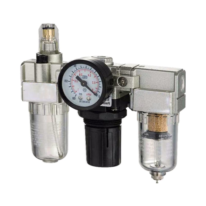
| Machine-level pressure and particles | filter-regulator or FRL | complete ISO class for the whole air stream |
A local FRL can filter particles, regulate pressure, and add lubrication when the downstream equipment requires it. It does not automatically deliver a specified ISO particles:water:oil class. A normal bowl filter cannot replace a dryer, and a lubricator can conflict with oil-sensitive processes.
The guide to coalescing filters and compressed-air quality explains aerosol removal. Use the pressure dew point guide when the main problem is condensation risk.
A Risk-Based Monitoring and Change-Control Plan
The current 9-page ISO 8573-1:2010 standard does not set one monthly or quarterly schedule. Parker emphasizes representative sampling and correct methods, while CAGI separates plant, instrument, and process-air risks (ISO, 2010; Parker, 2020; CAGI, 2026). Monitoring frequency should follow consequence and stability.
Set monitoring frequency from consequence and stability. A direct-contact process with no continuous oil or dew-point monitoring needs a different plan from a stable shop-air branch serving ordinary tools. The plan should also distinguish continuous indicators, routine verification, and event-driven testing.
Increase or repeat testing after:
- compressor replacement or lubricant change;
- dryer, filter, drain, or bypass maintenance;
- major pipework or hose replacement;
- unexplained product contamination or pneumatic failures;
- a dew-point, differential-pressure, or drain alarm;
- seasonal temperature changes that challenge the moisture margin;
- movement of a machine to a different branch;
- a failed result or deviation closure.
Use trends before fixed dates where practical. Continuous dew-point monitoring can reveal a dryer upset between laboratory campaigns. Differential pressure can show filter loading, but it cannot prove oil-vapor capacity or microbiological status. Follow equipment service limits as well as condition indicators.
| Record | Minimum content |
|---|---|
| Specification register | target class, location, owner, process risk |
| Sampling register | point ID, drawing reference, connection and purge method |
| Test report | method, instrument, calibration, uncertainty, operating conditions |
| Treatment record | element, dryer, drain, alarm, and bypass history |
| Deviation record | result, affected products or assets, containment and disposition |
| Change-control record | equipment or piping change, risk review, requalification decision |
How Do You Control Cost Without Inventing ROI?
CAGI recommends no more than 10% pressure drop from compressor discharge to point of use in a well-designed system. Air-quality treatment still consumes pressure margin through filters, dryers, fittings, and local hardware, so lifecycle cost must include energy and maintenance rather than only purchase price (CAGI, 2026).
Do not promise a universal 6-month payback, 20% defect reduction, or 300% maintenance saving. Build the business case from plant data:
- Current contaminant results at named points.
- Scrap, downtime, cleaning, component, and investigation costs tied to documented contamination events.
- Treatment capital, purge flow, pressure drop, power, elements, calibration, and laboratory testing.
- Production risk if the target is missed.
- Avoided central treatment when only one zone needs higher purity.
- Verification results after the change.
The strongest low-cost step is often measurement, not hardware. A sampling map can show that the central dryer meets its target while one wet branch fails, or that a local filter is adding pressure drop without solving oil vapor. That evidence narrows the corrective action.
For system-wide flow, storage, and treatment tradeoffs, use the guide to proper compressed-air system design. For line losses, see compressed-air pressure-drop troubleshooting.
Cost control improves when purity and pressure are accepted together. A project can meet its particle target and still fail production because fine filtration reduces machine-inlet pressure during peak flow. Commissioning should therefore record air quality, dynamic pressure, and operating state in the same acceptance package.
ISO 8573-1 Plant Management Checklist
Parker says an ISO 8573-1 classification requires correct sampling and test equipment; Part 1 is one document in a nine-part series. This checklist therefore covers specification, location, measurement, treatment, monitoring, records, and response instead of treating one filter certificate as plant compliance (Parker, 2020).
- Every critical use point has a particles:water:oil requirement or an approved reason why no class is assigned.
- The standard edition and sampling location appear on drawings and RFQs.
- Class 0 requirements include a numeric limit stricter than Class 1.
- Process and regulatory requirements beyond ISO 8573-1 are documented separately.
- Sampling points are clean, representative, accessible, and uniquely identified.
- Each contaminant uses the applicable ISO 8573 measurement method.
- Instruments, ranges, calibration, flow, pressure, temperature, and uncertainty are recorded.
- Central and point-of-use treatment have defined responsibilities.
- FRLs are not credited with drying or oil-vapor removal they cannot perform.
- Monitoring frequency is risk-based and includes change-triggered retesting.
- Pressure drop and dynamic machine-inlet pressure are checked with purity.
- Deviations identify affected products, equipment, containment, and corrective action.
- Requalification is considered after compressor, dryer, filter, or piping changes.
FAQs About ISO 8573-1 Compressed Air Quality Management
ISO 8573-1 has three classification tables, while the series contains nine parts. Class 0 must be stricter than Class 1, and ISO updated the oil-vapor method as ISO 8573-5:2025 (ISO, 2010; ISO 8573-5, 2025). These answers address common specification and verification errors.
Is Class 1:1:1 the highest compressed-air purity?
Not necessarily. Class 1 has defined limits, including oil at no more than 0.01 mg/m³. Class 0 can be stricter, but the user or supplier must write the actual limit and keep it within accurate measurement capability. Class 0 without the contaminant and numeric requirement is incomplete.
Can an FRL unit make compressed air ISO 8573-1 compliant?
An FRL can provide local particle filtration, pressure regulation, and optional lubrication, but it cannot prove all three purity classifications. Water vapor may require a dryer, oil aerosol may require coalescing filtration, and oil vapor may require adsorption. Validate the delivered air at the promised sampling point.
How often should compressed air quality be tested?
ISO 8573-1 does not set one universal monthly or quarterly interval. Base frequency on process consequence, historical stability, continuous monitoring, instrument capability, maintenance, and customer requirements. Retest after significant compressor, dryer, filter, bypass, lubricant, piping, or machine-location changes and after any failed result.
Does an oil-free compressor guarantee Class 0 at the point of use?
No. Compressor outlet performance does not prevent oil vapor from ambient intake, dirty distribution pipework, maintenance products, or downstream contamination. Class 0 also requires a written limit stricter than Class 1. Verify the actual air at the accepted location with the appropriate oil-aerosol and oil-vapor methods.
Where should ISO 8573-1 air quality be measured?
Measure at the location where the class is specified or accepted. Parker identifies compressor-room outlet and point-of-use locations as typical sampling areas. For troubleshooting, compare upstream and downstream points so the plant can separate central treatment performance from distribution or machine-level recontamination.
Source Notes and Retrieval Dates
- ISO 8573-1:2010, particles, water, oil, additional contaminants, and current-edition status. Retrieved 2026-07-11.
- ISO 8573-2:2018, liquid oil and oil-aerosol measurement. Retrieved 2026-07-11.
- ISO 8573-3:1999, humidity measurement. Retrieved 2026-07-11.
- ISO 8573-4:2019, particle-content measurement. Retrieved 2026-07-11.
- ISO 8573-5:2025, oil-vapor measurement. Retrieved 2026-07-11.
- ISO 8573-7:2003, viable microbiological contaminant testing. Retrieved 2026-07-11.
- Parker Compressed Air Purity Testing, class interpretation, sampling, and validation methods. Retrieved 2026-07-11.
- Parker Air Preparation Engineering Data, ISO class notation and treatment engineering data. Retrieved 2026-07-11.
- CAGI Compressed Air Purity Guide, class table, treatment stages, and plant, instrument, and process-air guidance. Retrieved 2026-07-11.
- CAGI Working With Compressed Air, compressed-air purity and pressure-drop resources. Retrieved 2026-07-11.
- YouTube: AIR QUALITY CLASSES ISO 8573 1, visual class overview by Mechanical Riveter. Retrieved 2026-07-11.