

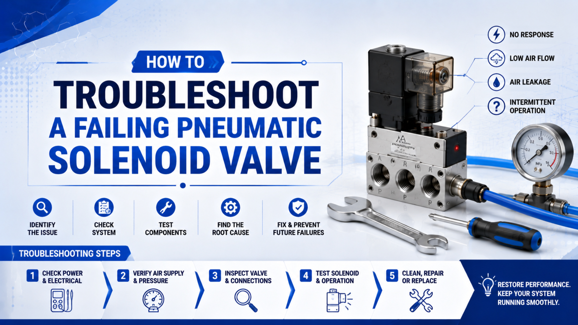
Pneumatic solenoid valve troubleshooting is the process of separating an electrical command problem from a coil, pilot, valve-body, air-path, or actuator fault. Start with the observed symptom. Then test one boundary at a time instead of replacing the valve because a cylinder stopped moving.
A useful diagnosis proves four events in order: the control output reaches the connector, the solenoid develops magnetic force, the valve element changes position, and compressed air reaches the correct actuator port. A click confirms only part of that chain. It does not prove adequate pilot pressure, spool travel, flow capacity, or cylinder force.
Key Takeaways
- Apply hazardous-energy controls under OSHA 29 CFR 1910.147 before opening a connector or pneumatic line.
- Test voltage while the command is present; test resistance only on an isolated circuit.
- A manual override separates electrical control from part of the pneumatic path.
- Use the valve nameplate and datasheet, not universal resistance or voltage limits.
Why Must You Isolate Energy Before Testing?
OSHA 29 CFR 1910.147 requires hazardous electrical and pneumatic energy to be isolated before covered servicing, with stored or residual energy relieved, restrained, or otherwise rendered safe (OSHA, Control of Hazardous Energy, accessed 2026). Follow the site’s approved procedure and verify isolation before contact.
Troubleshooting can include both de-energized and energized measurements, but they are not the same task. Resistance and continuity tests require an isolated circuit. Live voltage measurements require qualified personnel, suitable PPE, a correctly rated meter, and the site’s electrical safe-work procedure. If those controls aren’t available, stop and escalate the test.
Before touching the valve:
- Identify every electrical and pneumatic energy source.
- Put the machine in a safe mechanical state; block gravity or spring-driven motion where required.
- Apply lockout or tagout through the site’s authorized procedure.
- Isolate the compressed-air supply and bleed stored pressure from the affected volume.
- Verify electrical de-energization and zero pneumatic pressure with appropriate instruments.
- Confirm that the actuator cannot move unexpectedly before disconnecting tubing or removing the operator.
Don’t rely on a PLC output indicator, valve LED, closed hand valve, or regulator gauge as proof of isolation. OSHA specifically requires verification that isolation and de-energization have been accomplished. A manual override should be used only when the approved test plan allows the circuit to be pressurized and personnel are clear of motion hazards.
Start With the Symptom, Not the Spare Valve
Two ASCO examples show why the valve type matters: a direct-acting 109 model is rated for 0–15 bar air service, while a pilot-operated 551 model specifies 2–10 bar (ASCO 109, accessed 2026; ASCO 551, accessed 2026). For example, the same symptom can have different causes.
Use the symptom to select the next boundary test:
| Observed symptom | First boundary to test | Likely branches |
|---|---|---|
| No LED and no click | Control signal and connector | PLC output, fuse, wiring, common, connector |
| LED on but no click | Voltage at coil and coil continuity | Wrong voltage, open coil, connector contact, suppression module |
| Click but no air shift | Pilot pressure and valve mechanism | Low pilot pressure, manual override, blocked exhaust, contamination, stuck spool |
| Air shifts but actuator does not move | Working-port pressure and downstream path | Tube, speed controller, muffler, cylinder, load, mechanical jam |
| Intermittent operation or excess heat | Dynamic voltage, pressure, temperature, and duty | Loose connection, voltage sag, pressure sag, moisture, wrong coil, environment |
The diagnostic unit is not “the valve.” It is the boundary between two states. Prove command at the connector, magnetic action at the operator, pressure change at the valve port, and motion at the actuator. Each confirmed boundary removes an entire group of possible causes.
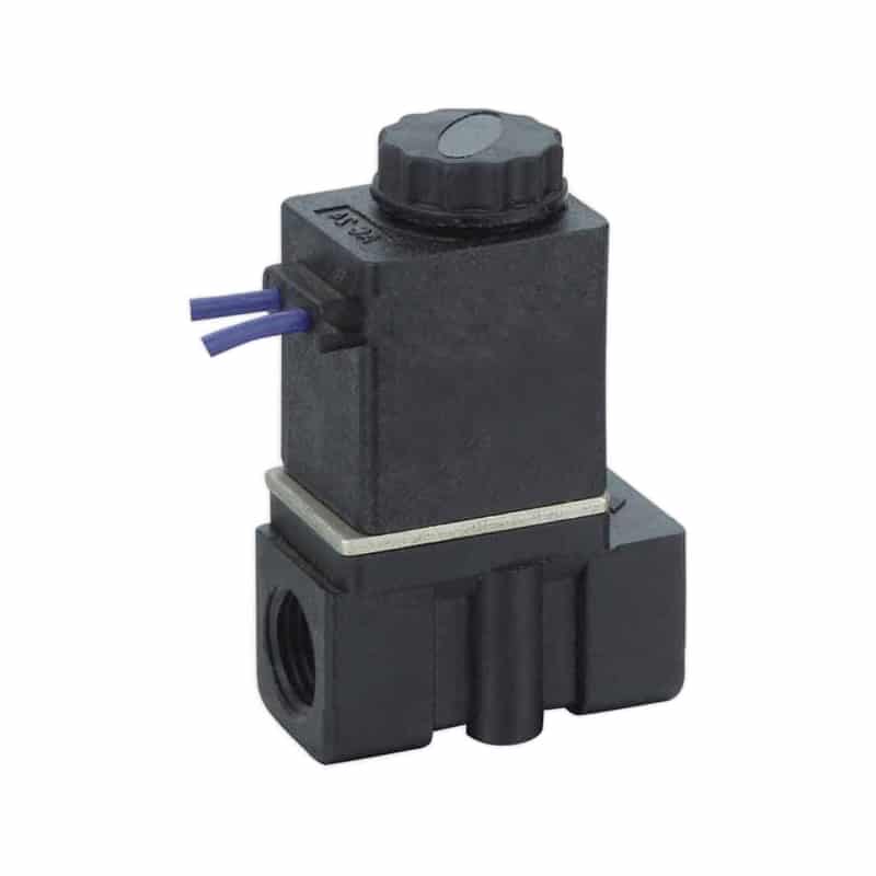
The valve’s function also changes the expected result. A 2/2 valve opens or closes one path. A 3/2 valve switches a working port between supply and exhaust. A 5/2 valve alternates two cylinder ports. Verify the port diagram and normal state before declaring a path blocked. The companion guide explains how pneumatic solenoid valves route compressed air.
What If the Valve Does Not Click?
One ASCO intrinsically safe 24 VDC operator specifies ±10% supply tolerance and at least 28 mA loop current, while a Festo 24 VDC pilot valve permits ±25% voltage fluctuation (ASCO ISSC-MXX instructions, accessed 2026; Festo VMPA1 datasheet, 2025). No click: measure coil voltage during the command, isolate the circuit, then test continuity against the exact coil data.
Start at the connector. Confirm the commanded output, common or return conductor, pin assignment, connector seating, cable condition, and any interposing relay. An illuminated connector LED proves that some voltage reaches the indicator circuit. It does not prove the coil sees the correct voltage under load.
Measure Voltage Under the Commanded Condition
If the site’s procedure permits energized testing, measure at the coil terminals while the output is commanded. Compare the measured voltage, AC frequency, polarity requirements, and permissible fluctuation with the valve documentation. A nominal 24 VDC supply at the cabinet can still sag at the connector because of a weak output, damaged cable, high-resistance contact, or shared load.
DC connectors may include a flyback diode, LED, or polarity-sensitive suppression module. Reversed polarity can leave the coil inactive even when a handheld voltage reading appears reasonable. AC coils require the stated voltage and frequency. Do not replace an AC coil with a DC coil, or the reverse, merely because the connector fits.
Test Continuity and Resistance With Power Off
Fluke instructs technicians to perform continuity testing with the circuit de-energized and the component isolated from parallel paths (Fluke, Continuity Testing Guide, accessed 2026). Disconnect the coil according to the manufacturer procedure before measuring it.
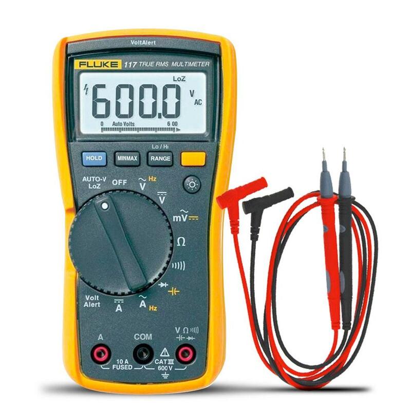
An OL or infinite reading usually indicates an open circuit, but a low reading is not automatically proof of a shorted coil. First short the test leads together and note their resistance. Fluke says good leads should read about 0.5 Ω or less, while some continuity functions may beep at resistance as high as 15 Ω (Fluke, Test Lead Guide, accessed 2026).
Compare the coil with its datasheet or an identical known-good coil at a similar temperature. Coil resistance changes with temperature, and AC coil operation depends on impedance, frequency, plunger position, inrush, and holding current. A universal “10–200 Ω is normal” rule cannot distinguish those designs.
What If It Clicks but Does Not Shift Air?
A Festo VMPA1 pilot-controlled valve specifies 3–8 bar pilot pressure and includes detenting or non-detenting manual overrides (Festo VMPA1 datasheet, 2025). A coil can click while the main stage remains stationary if pilot pressure is missing, too low, or routed incorrectly.
Check the supply at the valve while it is commanded, not only at the compressor or regulator. Confirm the correct supply port, external-pilot connection where used, exhaust availability, and minimum differential pressure. A blocked silencer or plugged exhaust gallery can stop a spool from completing its travel.
Use the manual override only under the approved pressurized test condition. Festo describes the override as a commissioning aid for checking the valve or valve-actuator combination (Festo MPAL-VI manual, 2017). Interpret the result carefully:
| Manual override result | What it suggests | Next check |
|---|---|---|
| Valve shifts and actuator moves | Pneumatic path can operate | Coil, connector, command voltage, suppression |
| Override moves but valve does not shift | Main stage or pilot path fault | Pilot pressure, contamination, mechanical binding |
| Valve shifts but actuator does not move | Fault is downstream | Working-port pressure, tubing, flow controls, cylinder, load |
| Override cannot be moved normally | Mechanical or configuration issue | Locking override state, operator instructions, valve damage |
Do not force the override or dismantle a pressurized valve. After isolation, inspect only to the level allowed by the manufacturer’s maintenance sheet. Incorrect reassembly can change the magnetic circuit, damage seals, or invalidate hazardous-area approval.
What If Air Shifts but the Actuator Does Not Move?
A Festo MVH 5/2 pilot valve lists 750 L/min nominal flow, 2–10 bar operating pressure, and separate 20 ms on and 36 ms off switching times (Festo MVH technical data, accessed 2026). Valve switching is only one part of the actuator’s pressure, flow, and force chain.
Measure pressure at both working ports during the command. If the valve outlet changes but the cylinder port does not, inspect tubing, quick couplers, flow controls, check valves, and fittings. If pressure reaches the cylinder but motion does not begin, check load, alignment, mechanical stops, guide binding, cushion settings, and required force.
Inspect both exhaust paths. A contaminated or undersized silencer can make a cylinder slow, prevent full pressure differential, or create different extension and retraction behavior. Check the meter-out controller’s direction; a reversed one-way flow control can restrict supply instead of exhaust.
Use two pressure readings instead of one guess: valve inlet during motion and the active cylinder port. Inlet collapse points upstream. Stable inlet with weak outlet points to the valve or exhaust logic. Correct cylinder-port pressure with no motion points to the actuator, load, or mechanics.
Related guides cover pneumatic cylinder fault isolation and the relationship between solenoid response and machine motion.
Why Does the Fault Appear Only Intermittently?
ASCO’s low-power operator instructions require the electrical load to remain within the nameplate range and warn that the solenoid can become hot during normal operation (ASCO ISSC-MXX instructions, accessed 2026). For an intermittent fault, capture connector voltage, inlet or pilot pressure, and temperature during the failing cycle; heat alone does not prove failure.
Intermittent faults need measurements during the failing cycle. For instance, log commanded state, voltage at the connector, valve-inlet pressure, relevant port pressure, coil or ambient temperature, and event time. A static bench reading taken after the fault disappears may show nothing wrong.
Work through these patterns:
- Fails after warming: check ambient temperature, duty rating, coil voltage, coil part number, enclosure, and heat sources.
- Fails during simultaneous machine motion: check supply-pressure sag, shared manifold capacity, output-module loading, and common return wiring.
- Fails with vibration: inspect connector retention, cable strain relief, terminal torque, damaged conductors, and intermittent test leads.
- Fails after washdown or condensation: inspect the specified enclosure rating, connector seal, cable entry, moisture, corrosion, and air quality.
- Drops out slowly: check suppression components, residual magnetism, spool friction, exhaust restriction, and the separate guidance on coil inductance and release time.
Do not cool a hot coil with water or solvent. Do not assume a hot continuous-duty coil is defective by touch. Use the manufacturer’s temperature and enclosure limits, protect accessible hot surfaces as required, and replace mismatched operators with the correct voltage, frequency, wattage, and approval.
Repair or Replace
ASCO states that maintenance timing depends on media and service conditions, recommends periodic cleaning on that basis, and calls for complete solenoid replacement when damage is present (ASCO EF maintenance instructions, accessed 2026). A universal 60–70% repair-cost threshold is not an engineering test.
Repair only when the manufacturer provides a permitted procedure and the failure is within that scope. Examples may include replacing the specified coil, connector, seal kit, or approved wear components. Record the original model, valve function, voltage, frequency, wattage, pressure range, orifice or flow rating, seal material, port interface, and approval markings before ordering parts.
Replace the complete valve or operator when:
- The body, armature tube, spool bore, coil enclosure, threads, or sealing surfaces are damaged.
- Correct voltage and pressure are present but the approved cleaning or service procedure does not restore repeatable operation.
- The required coil, seal kit, or internal parts are unavailable or not approved for field replacement.
- A hazardous-area or safety function would lose certification or traceability after repair.
- Repeated failures indicate wear that cannot be verified within specification.
- The replacement model cannot match the original function, flow, pressure, connector, or environmental requirements.
For replacement projects, use the detailed OEM solenoid valve compatibility checklist. A visually similar valve can still have a different normal state, pilot arrangement, pinout, pressure range, or exhaust behavior.
What Preventive Checks Reduce Repeat Failures?
One Festo valve allows lubricated operation only if lubrication is then maintained, while another Festo pilot valve states that lubricated operation is not possible (Festo MVH, accessed 2026; Festo VMPA1, 2025). Prevent repeat failures by following model-specific lubrication and air-quality limits, then recording dynamic voltage and pressure baselines.
Build the maintenance interval from risk and observed condition, not a generic monthly or quarterly schedule. A high-cycle valve in washdown service needs different checks from a sheltered valve that shifts twice per day. Follow the machine risk assessment and the valve manufacturer’s stated maintenance conditions.
Record baseline measurements when the system works: connector voltage under load, valve-inlet pressure during motion, working-port pressure, stroke time, ambient temperature, and sound or vibration notes. Troubleshooting becomes a comparison against known-good behavior instead of an argument about whether a warm coil or slow cylinder “looks normal.”
Use a condition-based checklist:
| Condition | Preventive check | Evidence to record |
|---|---|---|
| High cycle count | Response trend and leakage | Cycle count, command-to-pressure time, audible exhaust leakage |
| Washdown or humid area | Connector and enclosure sealing | Moisture, corrosion, seal condition, cable entry |
| Shared manifold | Dynamic pressure and electrical loading | Inlet pressure during simultaneous shifts, output current |
| Contaminated air history | Filter condition and valve symptoms | Differential pressure, drain condition, debris findings |
| Vibration | Connector and cable retention | Fastener condition, strain relief, intermittent voltage |
| Critical spare | Compatibility and storage review | Model, voltage, function, seals, pressure, expiry controls |
Document the failed boundary and corrective action. “Valve replaced” is not a root cause. “24 VDC command fell to 16 V at the connector when three outputs energized” or “pilot inlet dropped below the model’s minimum during clamp motion” gives the maintenance team something it can prevent.
FAQ
Fluke notes that continuity beepers can respond anywhere from 0 to 50 Ω depending on the meter, while Festo examples show permissible voltage fluctuations of ±10% or ±25% depending on the exact valve (Fluke, accessed 2026; Festo MVH, accessed 2026; Festo VMPA1, 2025). Model-specific data controls.
How do I know whether a pneumatic solenoid valve coil is open?
Follow the approved isolation procedure, disconnect the coil as instructed, verify the circuit is de-energized, and measure resistance across the isolated coil. An OL reading usually indicates an open path. Compare any finite value with the exact coil data or an identical known-good coil at similar temperature.
Does hearing a click prove that the solenoid valve works?
No. A click indicates movement in the electromagnetic operator, but it does not prove that a pilot stage has enough pressure, the main spool completed its stroke, the expected port changed pressure, or the downstream actuator can move. Check port pressure and manual-override behavior under an approved test condition.
Why does a pilot-operated valve click but pass no air?
Check the model’s minimum pilot or differential pressure, supply-port assignment, external-pilot connection, exhaust path, manual override, and spool condition. Pilot-operated valves need pneumatic energy to shift the main stage. A direct-acting valve may operate from zero differential, but that cannot be assumed for a pilot design.
Should a pneumatic solenoid coil feel hot?
Some continuous-duty coils become hot during normal service, so touch is not a pass-fail test. Compare voltage, frequency, duty, ambient temperature, coil part number, enclosure, and measured temperature with the manufacturer limits. Protect accessible hot surfaces and never cool an energized operator with water or solvent.
When should I replace the entire solenoid valve?
Replace it when the body or operator is damaged, approved service cannot restore repeatable switching, required parts are unavailable, or repair would compromise certification or traceability. For an OEM replacement, match valve function, normal state, voltage, pressure range, pilot method, flow, seals, port interface, and connector pinout.
Sources and Retrieval Notes
-
OSHA, The Control of Hazardous Energy, 29 CFR 1910.147, electrical and pneumatic energy isolation, stored-energy control, and verification requirements. Retrieved 2026-07-11.
-
Fluke, How to Test for Continuity, de-energized continuity-testing procedure. Retrieved 2026-07-11.
-
Fluke, How to Test Multimeter Test Leads, lead-resistance and continuity-beeper cautions. Retrieved 2026-07-11.
-
ASCO, ISSC-MXX Installation and Maintenance Instructions, nameplate limits, 24 VDC example, loop-current requirement, heat, isolation, and cleaning precautions. Retrieved 2026-07-11.
-
ASCO, EF Solenoid Installation and Maintenance Instructions, condition-dependent maintenance and replacement guidance. Retrieved 2026-07-11.
-
ASCO 109 product data, direct-acting 24 VDC valve and 0–15 bar air-pressure example. Retrieved 2026-07-11.
-
ASCO 551 product data, pilot-operated valve and 2–10 bar air-pressure example. Retrieved 2026-07-11.
-
Festo VMPA1 datasheet, pilot pressure, voltage fluctuation, manual override, air quality, and non-lubricated-operation limits. Published 2025-02-14; retrieved 2026-07-11.
-
Festo MVH product data, flow, pressure, switching time, voltage fluctuation, and lubrication conditions. Retrieved 2026-07-11.
-
Festo MPAL-VI manual, manual-override purpose and valve-actuator commissioning context. Published 2017-07; retrieved 2026-07-11.
-
AutomationDirect, Understanding Pneumatic Valve Ports and Ways, supply, working, and exhaust port context. Retrieved 2026-07-11.