

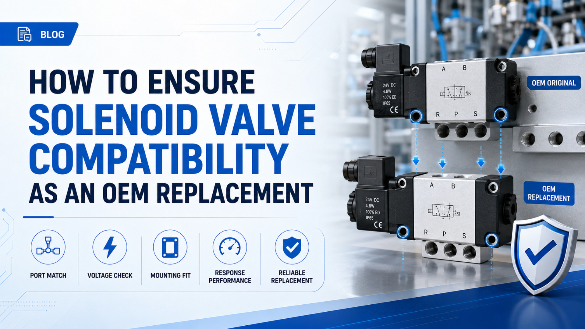
An OEM replacement solenoid valve is a substitute that reproduces the installed valve’s function, electrical load, pneumatic performance, physical interfaces, environmental limits, and safe failure behavior. A matching voltage and port thread aren’t enough. Release it only after its documents and first-article results pass a controlled comparison against the original requirement.
Key Takeaways
- Approve the replacement through 4 gates: function, interfaces, performance, and validation.
- Compare voltage, power, suppression, output capacity, and fault state together.
- Normalize Cv, Kv, pressure, and flow units before comparing catalogs.
- Freeze the approved part code, drawing, test record, and sample under change control.
Short Answer: Use Four Compatibility Gates
ISO 4414:2010 is the current third edition of the pneumatic-system safety standard and covers design, construction, modification, installation, operation, maintenance, reliability, and energy efficiency (ISO 4414, 2010). That scope supports a four-gate replacement decision instead of a one-line “equivalent” claim.
Approve each gate separately:
| Gate | Decision | Minimum evidence | Release condition |
|---|---|---|---|
| 1. Functional identity | Will the same ports connect in the same commanded and de-energized states? | Symbol, part-code decoder, circuit drawing | Every flow path and normal position match |
| 2. Interface compatibility | Will the valve connect without uncontrolled adapters or rewiring? | Dimensioned drawing, thread callouts, connector and pinout | Mechanical, pneumatic, and electrical interfaces match |
| 3. Performance equivalence | Will it meet flow, pressure, timing, leakage, duty, and environment requirements? | Catalog data under stated test conditions | Application limits and acceptance criteria pass |
| 4. Validated release | Can the approved configuration be reordered safely? | First-article report, machine trial, revision record | Exact part code and evidence package are frozen |
Treat the original part number as a clue, not the specification. A drop-in equivalent is a replacement that preserves the approved interfaces, function, performance, and fault behavior without uncontrolled changes. A new connector, pilot supply, exhaust, or PLC program makes the substitution an engineering change.
Does the Valve Function Match the Pneumatic Circuit?
One current Festo range lists nominal flows of 300 L/min for a 2/2 valve, 160 L/min for one 3/2 configuration, and 70 L/min for another 3/2 configuration (Festo solenoid valve data, 2026). Similar labels therefore don’t prove identical function or capacity.
Start with the valve symbol and the machine state table. Record whether the valve is 2/2, 3/2, 5/2, or 5/3; normally open or normally closed; monostable or bistable; direct acting or pilot operated; and internally or externally piloted. For a 5/3 valve, identify the exact center condition rather than writing only “5/3.”
The de-energized state matters most during a fault. A spring-return valve can vent, block, or pressurize an actuator port depending on its function. A bistable double-solenoid valve may retain its last commanded position after electrical power is removed. Neither behavior can be inferred from coil voltage.
For example, replacing a 5/2 spring-return valve with a 5/2 double-solenoid valve can preserve the port count while changing the power-loss state. The new valve may hold its last position instead of returning, so the actuator response and restart sequence must be reviewed.
Check these functional details against the circuit:
- Port identification and the complete flow path in every spool position.
- Return method, detent behavior, and manual override type.
- Pilot source, minimum pilot pressure, and external-pilot port requirements, including what happens when pilot pressure falls below the catalog minimum while the main supply remains available.
- Permitted flow direction and exhaust arrangement.
- De-energized, air-loss, and restart state of the actuator.
- Safety-related monitoring, redundancy, or diagnostic requirements.
For a broader explanation of valve architecture, see how pneumatic solenoid valves control compressed air. When pilot pressure is uncertain, also compare direct-acting and pilot-operated solenoid valves.
How Do You Match the Electrical Specifications?
A Festo direct-acting valve example uses 11 W at 24 V DC, while its listed switching times are 18 ms on and 20 ms off (Festo direct-acting valve data, 2026). Those figures show why voltage alone can’t establish coil or timing compatibility during selection.
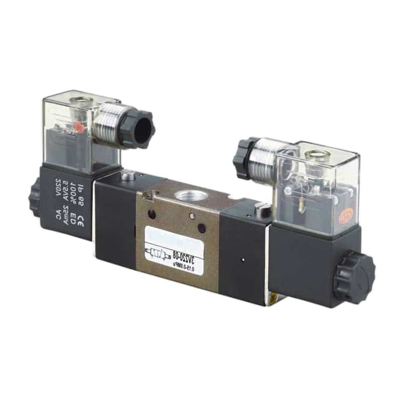
Copy the complete coil designation from the installed valve. Then compare rated voltage, AC frequency where applicable, permissible voltage range, steady power, inrush or pickup power, duty cycle, insulation class, connector, pinout, polarity, indicator, surge suppression, and protective earth requirements.
Catalog limits can differ even when two coils say 24 V DC. SMC lists a 24 V DC allowable range of -7% to +10% for some SY variants (SMC SY catalog, 2026). Apply the tolerance to voltage measured at the energized coil, including cable and output-device drop, not just the power-supply terminals.
The PLC or remote-I/O output must handle the actual load. Confirm per-channel current, group current, short-circuit behavior, leakage current, diagnostic pulse behavior, and whether the output expects a sourcing or sinking load. A connector adapter does not correct a power or logic mismatch.
Consider a 24 V DC coil that fits the connector but draws more pickup current than the PLC channel permits. The label voltage matches, yet the output can trip, overheat, or report a fault. That substitute fails the electrical gate before any pneumatic test begins.
Suppression devices deserve their own line in the comparison. A diode, Zener device, varistor, or RC network changes voltage polarity requirements and can change dropout time. If motion timing matters, compare the complete valve and driver combination using the separate guide to solenoid-valve response-time measurement.
| Electrical item | Evidence to request | Acceptance question |
|---|---|---|
| Supply | Voltage, AC frequency, tolerance | Does measured machine voltage remain inside the permitted range? |
| Load | Running power, pickup power, current | Can the output channel and group carry it? |
| Connection | Connector, pinout, polarity, earth | Does it mate without uncontrolled rewiring? |
| Suppression | Device type and wiring | Is it compatible with the output and required dropout time? |
| Duty | Continuous or intermittent rating | Does the real energization profile comply? |
Can the Pneumatic Performance Be Compared Directly?
ISO 6358-1:2013 defines steady-state tests for pneumatic components using compressible fluids, and its 2026 Amendment 2 addresses measurement uncertainty (ISO 6358-1, 2013; Amendment 2, 2026). Compare flow values only when their test methods and reference conditions are compatible during an OEM comparison.
Do not enforce a universal Cv tolerance. Instead, determine the flow needed at the actual upstream pressure, downstream pressure, duty, and allowable pressure loss. Then compare Cv, Kv, sonic conductance, critical pressure ratio, or standardized flow using the manufacturer’s definitions and curves.
ISO 6358-3:2014 covers both subsonic and choked flow and was confirmed current in 2025 (ISO 6358-3, 2014). This is why a single catalog flow number cannot describe every operating point. Supply pressure, downstream pressure, fittings, tubing, silencers, and shared exhaust paths all influence the machine result.
Record the following pneumatic limits:
- Minimum, normal, and maximum working pressure.
- Minimum pilot pressure and permitted pilot source.
- Proof pressure exactly as stated by the manufacturer, with no site-created multiplier substituted for the documented limit or approved test procedure.
- Flow data with reference conditions and flow direction.
- Internal and external leakage limits.
- Switching time under stated pressure and test conditions.
- Filtered-air, lubrication, dew-point, and contamination requirements.
- Exhaust backpressure and silencer restrictions.
Which Mechanical and Pneumatic Interfaces Must Match?
ISO 15407-1 covers five-port valve interfaces in 18 mm and 26 mm sizes for working pressure up to 1.6 MPa, or 16 bar, but explicitly does not standardize functional characteristics (ISO 15407-1, 2000). A standard footprint still needs a configured drawing comparison.
For an inline valve, verify every port thread by designation, size, gender, sealing method, and location. NPT, BSPT, BSPP, and metric threads aren’t interchangeable merely because their nominal sizes look similar. Also check wrench clearance, fitting orientation, tube bend radius, exhaust access, and the installed envelope with the connector attached.
For a plate-mounted or manifold valve, compare the mounting interface, gasket pattern, pilot and exhaust passages, station width, fasteners, electrical contact arrangement, and allowed manifold series. ISO 5599-1:2001 remains current after confirmation in 2024, but a compliant mounting surface does not make all configured valves functionally equivalent (ISO 5599-1, 2001).
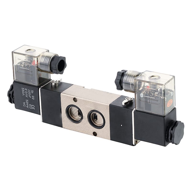
Use a drawing overlay for critical interfaces:
| Interface | Compare | First-article check |
|---|---|---|
| Base or bracket | Hole pattern, datum, fastener, gasket land | Measure and trial-fit without forcing |
| Ports | Function, thread, seal, direction | Gauge threads and verify correct tubing |
| Connector | Envelope, cable exit, latch, bend space | Mate the production harness |
| Manual override | Type, access, lock or detent | Operate under the approved procedure |
| Service access | Coil removal, fasteners, silencer clearance | Confirm maintenance can be completed safely |
What Environmental and Safety Conditions Apply?
OSHA 29 CFR 1910.147 includes pneumatic energy in its hazardous-energy scope and requires energy-control procedures to be inspected at least annually (OSHA 1910.147, accessed 2026). A replacement valve must preserve the machine’s isolation, bleed-down, and restart strategy for every approved installation.
Match ambient and media temperature, enclosure protection, humidity, washdown exposure, vibration, shock, corrosion, UV exposure, and any hazardous-area classification. Verify body, seals, lubricant, coil enclosure, connector, cable, and exhaust accessories separately. One acceptable material does not qualify the complete assembly.
An IP rating describes enclosure protection under defined tests. It does not prove chemical resistance, outdoor life, condensation control, or suitability for an explosive atmosphere. For hazardous locations, use the separate ATEX solenoid-valve selection guide and verify the complete certified configuration.
Stored pneumatic energy needs a physical control. OSHA identifies a line valve as an energy-isolating device and states that push buttons and selector switches are not isolation devices. Residual pressure must be dissipated or restrained before service (OSHA lockout procedure appendix, accessed 2026).
Component compatibility means the configured valve matches its approved interfaces and operating limits. It does not prove machine safety. A valve can match catalog data yet fail if its de-energized state, diagnostics, exhaust path, or restart response changes. Safety-related substitutions need formal change control.
How Should the First Article Be Tested?
ISO 12238:2023 is a 17-page, second-edition standard for measuring shifting time in electrically or pneumatically operated directional valves with two or three positions (ISO 12238, 2023). Use defined test conditions so the original and replacement timing results can be compared.
Do not apply an arbitrary 1.5-times-operating-pressure test. Use the proposed valve’s published proof pressure, the machine’s approved test procedure, applicable regulations, and risk controls. If these sources don’t authorize an elevated-pressure test, do not invent one.
Run the first article through five gates:
- Identity and documents: Confirm exact part code, revision, valve symbol, coil code, drawing, datasheet, declarations, and special instructions.
- Visual and dimensional inspection: Check ports, sealing faces, fasteners, connector, pinout, labels, override, and critical envelope dimensions.
- De-energized bench checks: Verify coil resistance against the supplier’s permitted range, absence of shorts to the body where applicable, and the correct unpowered flow state.
- Controlled functional test: Apply approved pressure and voltage. Record current, leakage, shifting behavior, pressure loss, and response time under stated conditions, with instruments and acceptance limits identified before the test begins.
- Machine trial: Test normal production, simultaneous demand, power loss, air loss, emergency condition, restart, sensor confirmation, and maintenance isolation.
Define every pass limit before testing. “Works normally” isn’t a result. Record the instrument, calibration status, pressure, temperature, supply voltage, command, measured value, acceptance limit, and disposition.
The most useful machine-trial measurement is often not the valve’s unloaded bench flow. It is the actuator result under the worst valid demand group: dynamic inlet pressure, stroke time, end-sensor confirmation, and fault-state behavior measured together. This connects catalog equivalence to the actual production requirement.
How Do You Build a Reusable Replacement Evidence Package?
ISO 19973-1:2015 supplies general procedures and reporting methods for reliability assessment of pneumatic components (ISO 19973-1, 2015). A maintenance replacement does not need a full reliability program, but it does need traceable evidence that identifies exactly what was approved and tested.
Keep these records in one controlled package:
- Original and approved replacement part numbers with revision status.
- Original nameplate photos and machine location.
- Circuit symbol and required normal, commanded, and fault states.
- Comparison matrix for electrical, pneumatic, mechanical, and environmental data, including the source and revision of every value used to approve the cross-reference.
- Supplier drawings, datasheets, declarations, and installation instructions.
- Adapter or wiring drawings if the change is not truly drop-in.
- First-article inspection and machine-trial results.
- Approved deviation, risk review, and retest scope where applicable.
- Golden sample or controlled photographs of the accepted configuration.
- Purchasing note that prohibits unreviewed part-code substitutions.
Link the package to the machine bill of materials and spare-parts record. For valve islands, also preserve station number, pressure zone, pilot source, fieldbus mapping, and exhaust configuration. The modular pneumatic circuit worksheet provides the wider circuit context.
The release should state one of three outcomes: drop-in equivalent, approved replacement with controlled changes, or not compatible. This wording prevents a mechanical fit from being mistaken for complete equivalence.
FAQs About Solenoid Valve Compatibility
ISO 5599-1 was confirmed current in 2024, while ISO 15407-1 remains limited to 18 mm and 26 mm five-port mounting interfaces (ISO 5599-1, 2001; ISO 15407-1, 2000). These standards help with fit, but the FAQs below address the remaining functional decisions in practice.
Can I use a valve with a higher pressure rating?
A higher maximum rating does not automatically make the valve compatible. Confirm the minimum operating and pilot pressures, flow capacity, leakage, spool function, seal materials, proof-pressure documentation, and fail state. A valve designed for a wider pressure range can still behave differently at the machine’s normal operating point.
Is matching 24 V DC enough for the coil?
No. Compare permissible voltage tolerance, running and pickup power, duty cycle, polarity, connector, pinout, indicator, surge suppression, insulation, grounding, and PLC output capacity. SMC’s published -7% to +10% range for some 24 V DC SY variants shows that the full catalog limit matters.
Must Cv match within 10%?
There is no universal 10% rule. Establish the required actuator motion and allowable pressure loss, then compare flow data produced under compatible reference conditions. If one catalog gives Cv and another gives Kv, normalize the coefficient first and confirm the decision against supplier curves and a machine trial.
Can NPT and BSP ports be connected with an adapter?
An engineered adapter may make the connection possible, but the result is not a drop-in replacement. Review sealing method, pressure rating, flow restriction, installed length, orientation, wrench clearance, tube load, leak points, and service access. Record the adapter in the controlled drawing and bill of materials.
When must the replacement be treated as an engineering change?
Treat it as an engineering change when it alters wiring, PLC configuration, valve function, pilot supply, flow or timing, manifold passages, mounting hardware, fault state, safety function, environmental rating, or acceptance limits. Repeat every affected verification and validation test before production release.
Conclusion
The 2026 amendment to ISO 6358-1 adds measurement-uncertainty guidance to pneumatic flow testing, reinforcing a practical rule: replacement evidence must include conditions, not just numbers (ISO 6358-1 Amendment 2, 2026). Approve the exact configured valve through function, interface, performance, and validation gates for release.
Source Notes
- ISO, ISO 4414:2010. Retrieved July 11, 2026. https://www.iso.org/standard/44790.html
- ISO, ISO 6358-1:2013. Retrieved July 11, 2026. https://www.iso.org/standard/56612.html
- ISO, ISO 6358-1:2013/Amd 2:2026. Retrieved July 11, 2026. https://www.iso.org/standard/88078.html
- ISO, ISO 6358-3:2014. Retrieved July 11, 2026. https://www.iso.org/standard/56616.html
- ISO, ISO 15407-1:2000. Retrieved July 11, 2026. https://www.iso.org/fr/standard/27625.html
- ISO, ISO 5599-1:2001. Retrieved July 11, 2026. https://www.iso.org/standard/33074.html
- ISO, ISO 12238:2023. Retrieved July 11, 2026. https://www.iso.org/standard/77084.html
- ISO, ISO 19973-1:2015. Retrieved July 11, 2026. https://www.iso.org/standard/62570.html
- OSHA, 29 CFR 1910.147. Retrieved July 11, 2026. https://www.osha.gov/laws-regs/regulations/standardnumber/1910/1910.147
- Festo, Directly Actuated 2/2-Way Solenoid Valves. Retrieved July 11, 2026. https://media.festo.com/media/204680_documentation.pdf
- SMC, Series 10-SY 5-Port Solenoid Valves. Retrieved July 11, 2026. https://www.smcworld.com/catalog/Clean-en/pdf/sy_en.pdf