

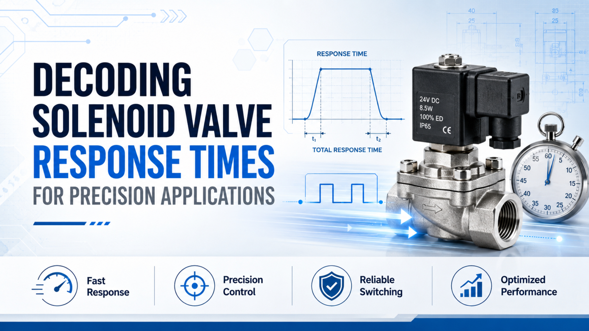
Solenoid valve response time is the interval between an electrical command and a clearly defined valve or pneumatic event. For a precision machine, the useful number is rarely the coil’s pickup time alone. The controller, driver, armature, spool or poppet, air path, tube volume, exhaust restriction, actuator, and sensor all consume part of the timing budget. A catalog value can help shortlist a valve, but it can’t predict the complete machine cycle unless the test boundary and operating conditions match the application.
Key Takeaways
- ISO 12238 defines valve shifting tests.
- SMC product configurations span 12 to 64 ms under stated conditions, so there is no universal range.
- Keep a precision process inside its timing window by budgeting driver, valve, tubing, exhaust, actuator, sensing, and variation separately.
For the detailed test setup, thresholds, and sensor placement, use the guide to measuring pneumatic solenoid valve response time. This article focuses on the next decision: turning a process requirement into a defensible timing budget and valve specification.
Why Is a Catalog Response Time Not a Machine Guarantee?
ISO 12238:2023 covers shifting-time procedures for electrically or pneumatically operated directional control valves with 2 or 3 positions (ISO 12238, 2023). That scope is narrower than machine response, which continues through pressure change, actuator travel, and sensor confirmation.
Use four boundaries when discussing a fast pneumatic sequence:
| Timing boundary | Starts at | Ends at | Best use |
|---|---|---|---|
| Electrical response | controller command | current reaches a defined level | driver and coil diagnosis |
| Valve shifting time | electrical or pilot command | main valve changes state | valve comparison |
| Pneumatic response | command | pressure reaches a defined threshold | valve, tube, and exhaust review |
| Machine response | command | actuator or process sensor confirms the event | cycle-time acceptance |
The same valve can produce four different numbers because each measurement stops at a different physical event. A specification that says only “response time under 20 ms” is incomplete. Does it mean coil current, valve shift, pressure at port A, or the cylinder’s end sensor? Treat energizing and de-energizing as separate budgets. Pickup depends on current rise and available magnetic force. Release depends on current decay, suppression, return spring force, spool friction, and the exhaust path.
For the electrical part of that chain, see how coil inductance affects solenoid response. Keep that value separate from the pneumatic result.
How Should You Build a Response-Time Budget?
SMC’s 10-SY clean-series data lists response limits from 12 ms for a 2-position 10-SY3000 configuration to 64 ms for a 3-position 10-SY9000 configuration at 0.5 MPa (SMC 10-SY catalog, 2026). The spread shows why a budget must use the exact valve function and SKU.
Start with the process event that can’t be late. Then work backward.
- Define the machine event, such as clamp pressure achieved or a part released.
- State the maximum command-to-event time and allowed variation.
- Reserve time for controller output, driver behavior, valve shift, tube fill or exhaust, actuator motion, and sensor confirmation.
- Add a margin for temperature, supply variation, wear, and measurement uncertainty.
- Convert the valve share into an acceptance statement with pressure, voltage, threshold, and test volume.
An allocation is an engineering decision, not a universal ratio. Suppose a station allows 60 ms from PLC output to confirmed pressure. The team might initially reserve 5 ms for controls, 20 ms for the valve, 25 ms for the pneumatic path, and 10 ms for sensing and margin. Those figures are a design example, not a catalog benchmark. Measurement decides whether the allocation is realistic.
Ask one uncomfortable question early: what happens if the valve meets its catalog limit but the machine still misses the event? If the specification contains no tube length, downstream volume, exhaust condition, or sensor threshold, the supplier and machine builder may both pass their tests while the station fails.
Why Do Maximum Delay and Timing Variation Need Separate Limits?
SMC expresses its selected 10-SY response values as limits such as 12 ms or less and 35 ms or less at 0.5 MPa, not as one family average (SMC 10-SY catalog, 2026). A precision specification also needs repeat-to-repeat variation, because a stable 24 ms event can be easier to schedule than an event wandering between 12 and 30 ms.
Track at least three values for each timing boundary:
| Timing measure | What it reveals | Design use |
|---|---|---|
| Maximum observed delay | latest event in the tested set | compare with the hard process deadline |
| Minimum-to-maximum range | repeat-to-repeat spread | reserve timing margin and detect instability |
| Cold and warm results | temperature sensitivity | check startup and continuous-duty behavior |
Do not hide the spread inside an average. A mean can look acceptable while occasional late cycles cross the process window. Record the cycle count, operating state, and raw extrema beside any average or percentile used by the quality team. Budget delay and variation separately. Fixed delay can often be offset in PLC sequencing. Random or condition-dependent variation is harder because the controller cannot safely compensate for an event that moves around. If the process is sensitive to arrival time, repeatability may matter more than shaving a few milliseconds from the nominal result (SMC 10-SY catalog, 2026).
Tube volume follows V = pi x ID^2 x L / 4. Doubling the internal diameter produces four times the physical volume at the same length. That doesn’t mean a smaller tube is always faster, because a smaller flow area can create more restriction. Response design must balance volume against flow capacity and pressure drop.
Which Architecture Choices Protect Timing Margin?
At 0.5 MPa, SMC lists 10-SY3000 2-position single response at 12 ms or less without a suppressor, while comparable 10-SY9000 data reaches 35 ms or less; some suppressed 3-position configurations reach 64 ms (SMC 10-SY catalog, 2026). Architecture can preserve or consume the margin left by that valve.
Use the exact datasheet instead of rules such as “direct acting is always faster.” Direct action removes a pilot stage, but moving mass, orifice, pressure force, coil, and driver remain. Pilot operation adds pilot pressure and main-stage dynamics. The guide to direct and pilot-operated valves covers that selection, while Cv sizing handles airflow.
Peak-and-hold drive can accelerate current buildup and reduce steady heating, but it must match the selected coil and power electronics. A simple flyback diode protects the switch with a low clamp voltage and can extend current decay. Faster clamps raise the turn-off voltage, so the driver, connector, insulation, and EMC design must tolerate the chosen method.
Place the valve close to the actuator when the process needs a steep pressure edge. Shortening the line reduces stored volume, but don’t choose tubing by length alone. Internal diameter, fitting bore, valve flow, actuator volume, and required mass flow belong in the same review. Exhaust deserves the same attention as supply. A loaded muffler, restrictive manifold passage, shared exhaust gallery, or meter-out flow control can consume release-time margin while the valve itself still shifts within its limit.
Use a quick-exhaust valve only when the safety review supports local exhaust. For system losses, use the guides to compressed-air pressure drop and valve placement.
How Should Precision Applications Allocate the Budget?
SMC states that its 10-SY response table uses 0.5 MPa, while the dynamic-test note identifies rated voltage and a 20°C coil temperature for the stated condition (SMC 10-SY catalog, 2026). Each precision process should allocate margin around its own consequence of being early, late, or inconsistent.
| Precision application | Define the final event | Protect this part of the budget | Common specification mistake |
|---|---|---|---|
| Dispensing | stable pressure or delivered shot begins | valve opening plus fluid or air-path fill | timing the electrical click instead of material delivery |
| Sorting and reject gates | part clears the decision point | command, valve shift, actuator travel | ignoring sensor and PLC output latency |
| Clamp and release | clamp pressure or safe release achieved | pressure threshold and exhaust decay | using cylinder end position as a pressure guarantee |
| Pick-and-place vacuum | vacuum threshold achieved or released | ejector, tube volume, cup leakage, release flow | quoting valve response without evacuation time |
| Purge or gas switching | defined concentration or pressure reaches the chamber | valve shift, line volume, chamber exchange | assuming valve shift equals process-gas arrival |
The budget should follow the physical condition that protects quality. A dispensing valve may need a repeatable start edge. A clamp may care more about verified pressure. A reject gate cares about position before the product reaches a fixed point. The same 20 ms valve allocation can therefore represent different test boundaries. For processes with a hard early limit as well as a late limit, write both. A release that occurs too soon can be as damaging as one that occurs late.
How Do You Validate Margin at Design Freeze?
ISO 12238:2023 is a 17-page standard for valve shifting-time procedures, while a design-freeze review must also confirm the process boundary and reserved margin (ISO 12238, 2023). Use the standard for the valve event, then compare the full command-to-process result with the approved budget worksheet.
Compare three boundaries: valve-outlet pressure, actuator-port pressure, and the process sensor. The response-time measurement guide covers equipment and thresholds. The design-freeze record only needs the approved limit, observed maximum, observed range, test state, and remaining margin for each boundary.
Repeat cold and warm, at permitted pressure and voltage extremes, with representative load and exhaust hardware. Save raw traces. Precision means the complete event stays inside its window across realistic conditions, not that one room-temperature cycle produces the smallest number.
What Should the RFQ and Acceptance Test State?
ISO 12238:2023 applies to monostable and bistable pneumatic directional valves with 2 or 3 positions (ISO 12238, 2023). An RFQ should add the exact operating conditions and output threshold, because valve function alone does not define the response event the machine needs.
Use a statement that can be reproduced:
At the stated supply pressure and coil voltage, command-on to the defined pressure threshold at the specified port and downstream volume shall not exceed the agreed limit. Command-off shall be tested separately with the specified exhaust hardware.
Then include:
| RFQ field | Required detail |
|---|---|
| Valve function | ports, positions, normal state, return method |
| Electrical | voltage, tolerance, driver, connector, suppression |
| Pneumatic | media, pressure range, flow requirement, exhaust routing |
| Test boundary | start signal, measured port, sensor, threshold |
| Test volume | tube ID and length, cavity, actuator if included |
| Environment | temperature, duty cycle, contamination, vibration |
| Acceptance | energize and release limits, repeats, min/mean/max |
Ask the supplier for the test method behind any published response number. If the catalog gives only one value, confirm whether it represents energizing, de-energizing, a mean, or a maximum. Also confirm whether a surge suppressor, indicator, power-saving circuit, or manifold configuration changes the stated value.
Conclusion
SMC’s documented 12-64 ms span across selected 10-SY configurations at 0.5 MPa shows why “typical solenoid valve response time” is not a safe design input (SMC 10-SY catalog, 2026). Precision comes from matching one tested valve configuration to one explicit system boundary.
Define the event first. Allocate time to controls, driver, valve, line, exhaust, actuator, and sensing. Then measure at the valve outlet, actuator port, and machine sensor to locate the real delay. A complete response-time budget turns a vague request for a “fast valve” into a testable engineering requirement.
FAQs About Solenoid Valve Response Times for Precision Applications
ISO 12238:2023 covers shifting-time tests for both electrically and pneumatically operated directional valves with 2 or 3 positions (ISO 12238, 2023). The answers below keep that valve boundary separate from tubing, actuator motion, and the complete machine event.
What is a good solenoid valve response time?
There is no universal good value. SMC lists 12 ms or less for one 10-SY3000 2-position configuration and 35 ms or less for a larger 10-SY9000 example at 0.5 MPa. Compare the exact function, pressure, voltage, suppression, and test boundary with the time allocated by the machine.
Is valve shifting time the same as cylinder stroke time?
No. ISO 12238 addresses directional-valve shifting time, while cylinder stroke time also includes line volume, available flow, exhaust restriction, piston area, load, friction, cushioning, and sensor location. Measure pressure near the valve before measuring at the cylinder if you need to separate component delay from machine motion.
Can higher voltage make a solenoid valve switch faster?
A suitable driver can ramp solenoid current quickly, and TI’s DRV110 supports configurable peak and hold behavior. Do not overvoltage a standard coil directly. The coil, driver, connector, suppression, insulation, thermal limit, and EMC design must all support the waveform. Verify voltage and current at the real machine connector.
Why can a surge suppressor change release time?
The coil stores magnetic energy. A low-voltage flyback path lets current decay more slowly, which can delay armature release even though it protects the switch. SMC therefore publishes different response limits for some suppressor options. Compare pickup and release separately, and use only a clamp voltage that the complete electrical design can tolerate.
How can I tell whether the valve or tubing is slow?
Measure command-to-pressure at the valve outlet, then repeat at the actuator port. If the first trace is fast and the second is late, inspect tube volume, ID, fittings, manifold restrictions, flow controls, and exhaust. The tube-volume calculator helps quantify stored volume, but the pressure traces identify where the delay actually appears.
Sources
ISO. ISO 12238:2023, Pneumatic fluid power, directional control valves, measurement of shifting time. Scope, valve functions, and publication details. Retrieved 2026-07-11.
SMC Corporation. Series 10-SY3000/5000/7000/9000 catalog. Product-specific response limits, 0.5 MPa test pressure, temperature, voltage, valve function, and suppressor conditions. Retrieved 2026-07-11.
Texas Instruments. DRV110 Solenoid Current Controller Datasheet. Fast current ramp, peak-and-hold operation, supply arrangements, and configurable current-control parameters. Retrieved 2026-07-11.
AutomationDirect. Understanding Pneumatic Valve Ports and Ways. Video background for identifying the measured pneumatic event. Retrieved 2026-07-11.