

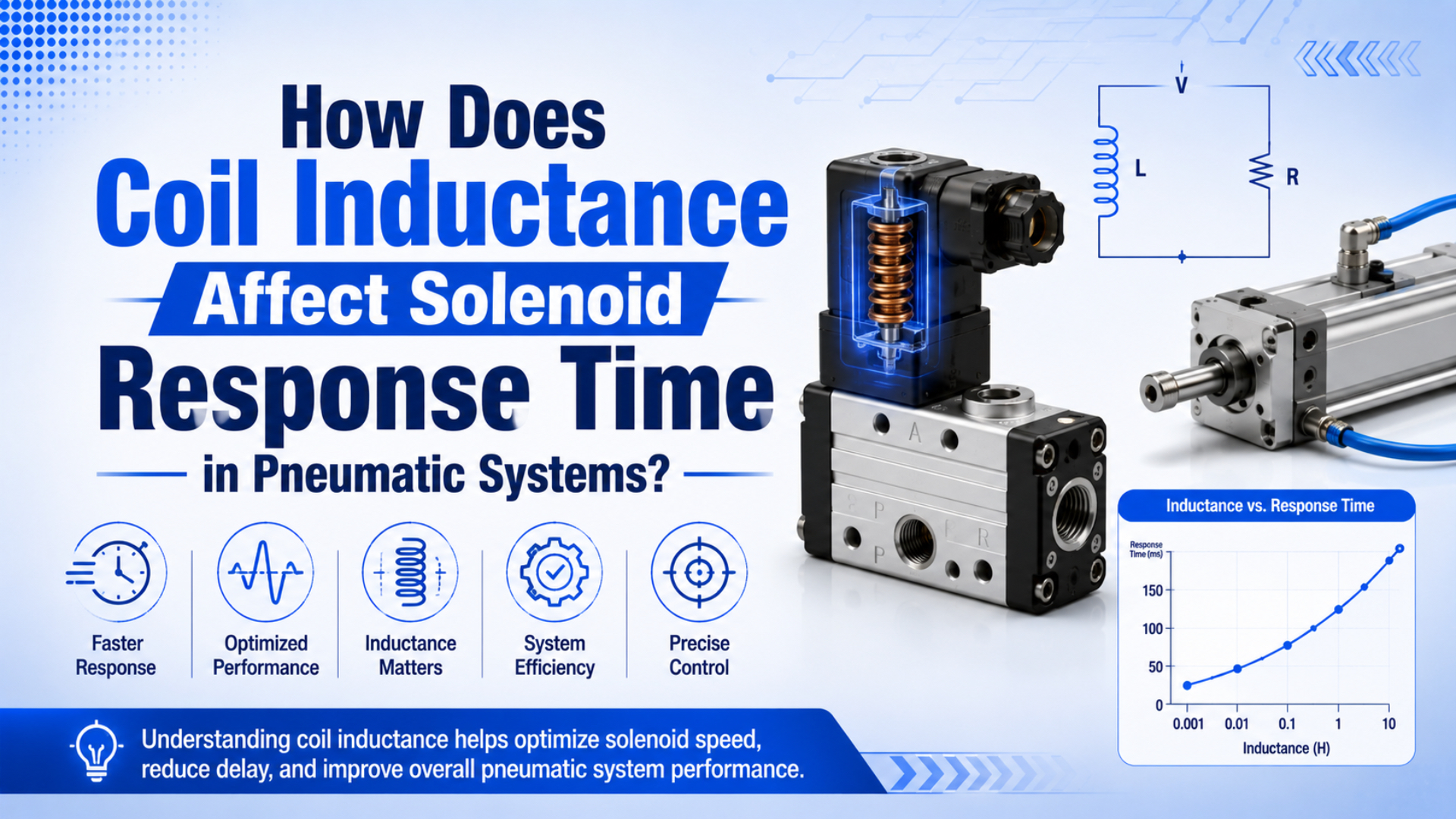
Coil inductance is the electrical property that makes a solenoid coil resist sudden current change. In a pneumatic solenoid valve, that matters because coil current must build enough magnetic force to move the plunger, pilot stage, or armature before the valve can route compressed air.
The practical answer: higher inductance usually slows pickup current rise and can also slow dropout current decay. However, response time is never only an electrical number. Driver voltage, coil resistance, suppression circuit, spring force, pilot pressure, spool friction, port flow, and actuator volume all add delay.
Key Takeaways
- In an RL circuit, one time constant reaches about 63.2% of the final current; for a coil,
tau = L / R.- TI’s DRV110 solenoid controller uses fast current ramp-up, then lower hold current to reduce heat.
- Treat solenoid response as a budget: driver delay, coil current, armature motion, valve shift, air fill, and exhaust.
In our experience, the most common timing mistake is blaming the coil for the whole stroke. A 20 ms electrical delay matters on a high-speed packaging jaw, but a long tube, small muffler, low point-of-use pressure, or undersized valve can add more delay than the coil itself.
For the broader valve overview, see how pneumatic solenoid valves control compressed air.
What is coil inductance in a pneumatic solenoid?
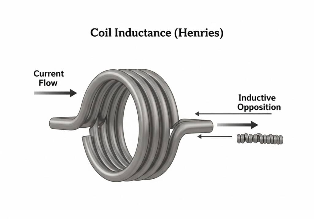
Coil inductance is the tendency of a conductor to oppose current change, and the SI unit is the henry. Tameson describes a solenoid valve as 2 main parts, a solenoid and a valve body, so inductance belongs to the electrical actuator side, not the air ports (Tameson, 2024).
In a pneumatic solenoid valve, the coil is wound around a magnetic path. When voltage is applied, current rises through the winding. That current creates magnetic flux. The magnetic field then pulls a plunger, armature, or pilot element against spring force and friction.
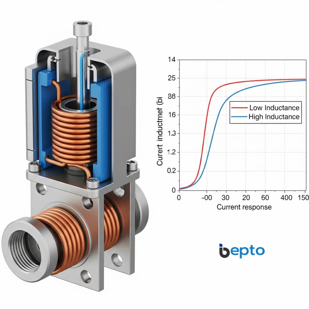
Inductance is not the same as resistance. Resistance limits steady current. Inductance limits how fast current can change. Therefore, 2 coils with the same nominal voltage can feel different on a machine if their inductance, resistance, magnetic circuit, or driver is different.
For pneumatic troubleshooting, keep the boundary clear:
| Area | Belongs to | What it affects |
|---|---|---|
| Coil inductance | electrical side | current rise and decay |
| Coil resistance | electrical side | final current and heat |
| Plunger and spring | electromechanical side | pickup and dropout threshold |
| Pilot passage or spool | valve side | air routing delay |
| Cylinder chamber and exhaust | pneumatic side | actuator motion delay |
We usually ask for both the coil label and the valve function when a customer reports “slow solenoid response.” Coil voltage alone is not enough. A replacement coil can be electrically compatible but still shift at a different point if current ramp, spring force, or pilot pressure changed.
How does the L/R time constant create pickup delay?
An RL circuit reaches about 63.2% of its final current after one time constant, and the time constant is tau = L / R. Therefore, a solenoid coil with higher inductance or lower effective resistance takes longer to build current after the command turns on (RL circuit reference, 2026).
The simplified energizing equation is:
I(t) = I_final x (1 - e^(-t/tau))
Where:
| Symbol | Meaning | Practical note |
|---|---|---|
I(t) |
coil current at time t |
what creates magnetic force |
I_final |
steady-state current | roughly voltage divided by resistance |
L |
coil inductance | higher L slows current change |
R |
effective resistance | winding plus driver path |
tau |
time constant | L / R, in seconds |
The valve does not wait for 100% of steady current. It picks up when magnetic force exceeds spring force, seal force, friction, and any pressure-related load. On one coil, that may happen before one time constant. On another, it may need several time constants.
As a result, a simple L/R calculation is a first estimate, not a final response-time guarantee. The pickup threshold, supply voltage tolerance, temperature, driver current limit, and valve mechanics still matter.
Why can dropout be slower than pickup?
Dropout delay depends on how quickly stored coil energy is removed after the command turns off. TI’s DRV110 datasheet describes solenoid current ramp-up for activation, then a lower hold current for reduced heat (Texas Instruments DRV110, 2018).
When power is removed, coil current does not disappear instantly. The magnetic field collapses and the coil generates voltage that opposes the current change. Therefore, the suppression circuit decides where that energy goes and how quickly current decays.
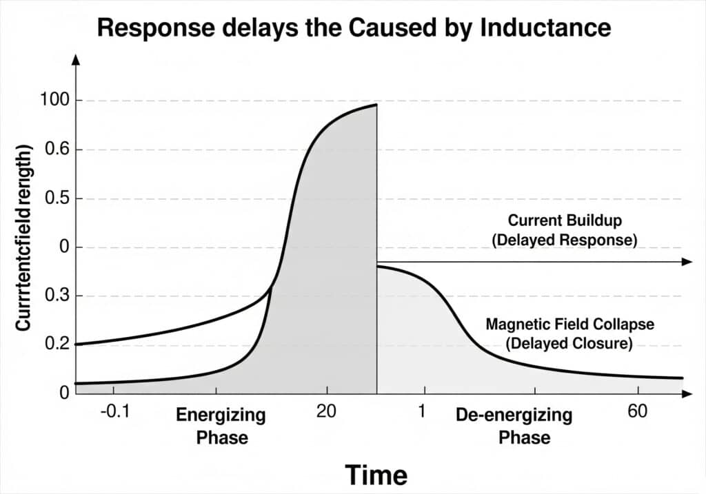
A simple flyback diode protects the switching device by clamping voltage to a low level. That is gentle on electronics, but it can let coil current circulate longer. By contrast, a higher-voltage clamp, TVS device, or zener-assisted suppression can reduce dropout delay. Check switch and insulation ratings first.
The pneumatic side can hide this effect. A valve may drop out electrically, but the cylinder may still finish motion late because the exhaust side is restricted. Therefore, measure both coil voltage/current and actuator motion before changing suppression parts.
Which coil and driver choices reduce response delay?
Driver design can reduce response delay even when the coil inductance is fixed. TI’s DRV110 lists a 50 us start-up delay before gate-driver switching at 20 kHz and describes peak and hold current levels (Texas Instruments DRV110, 2018).
Peak-and-hold control is useful because pickup and hold are different jobs. First, pickup needs enough current quickly to move the plunger. Then, hold only needs enough magnetic force to keep the valve shifted after the air path is established.
Use these levers carefully:
| Lever | Response benefit | Tradeoff |
|---|---|---|
| Higher initial voltage | faster current rise | coil heat, insulation stress, driver rating |
| Peak-and-hold driver | fast pickup with lower hold heat | added electronics and setup |
| Lower inductance coil | faster current change | may need higher hold current |
| Higher clamp voltage | faster dropout | switch voltage stress |
| Shorter cable and clean supply | less voltage drop and noise | wiring layout discipline |
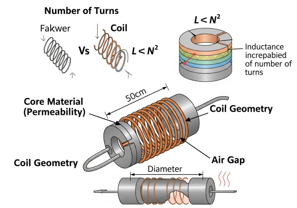
Coil geometry also matters. More turns, a high-permeability magnetic path, and a smaller air gap can increase inductance and magnetic force. Fewer turns or a different winding can reduce inductance, but the valve still needs enough ampere-turns to shift reliably across voltage and temperature variation.
The practical specification is not “lowest inductance.” Instead, the target is pickup current fast enough, stable hold without overheating, fast release, and a switching circuit that survives the clamp voltage.
How do you separate coil delay from pneumatic motion delay?
Separate coil delay from pneumatic delay by measuring the event in stages. SMC gives cylinder speed as s = 28.8q / A, tying actuator speed to air flow and piston area, while coil timing only starts the valve event (SMC, 2026).
For a complete timing review, split the response budget:
- PLC or relay output delay.
- Solenoid driver delay.
- Coil current rise or decay.
- Plunger or armature movement.
- Pilot stage and main spool movement.
- Pressure build-up in the working port.
- Exhaust flow from the opposite chamber.
- Cylinder or actuator motion to the sensor point.
If the machine has a fast oscilloscope or current probe, measure coil current directly. If not, use practical markers: PLC output timestamp, valve LED, audible click, pressure switch change, cylinder reed switch, and machine sensor arrival. Then compare the timing gaps.
For valve and port selection, link this article back to pneumatic solenoid valve operation, pilot operated valve behavior, and Cv sizing for pneumatic valves. Coil timing does not replace flow sizing.
RFQ checklist for fast-response solenoid valves
A fast-response solenoid valve RFQ should include voltage, coil data, response target, valve function, pressure, flow, and driver details. Tameson separates 3 solenoid operating types, while TI separates peak current, hold current, keep time, and PWM frequency in its driver setup (Tameson, 2024; Texas Instruments DRV110, 2018).
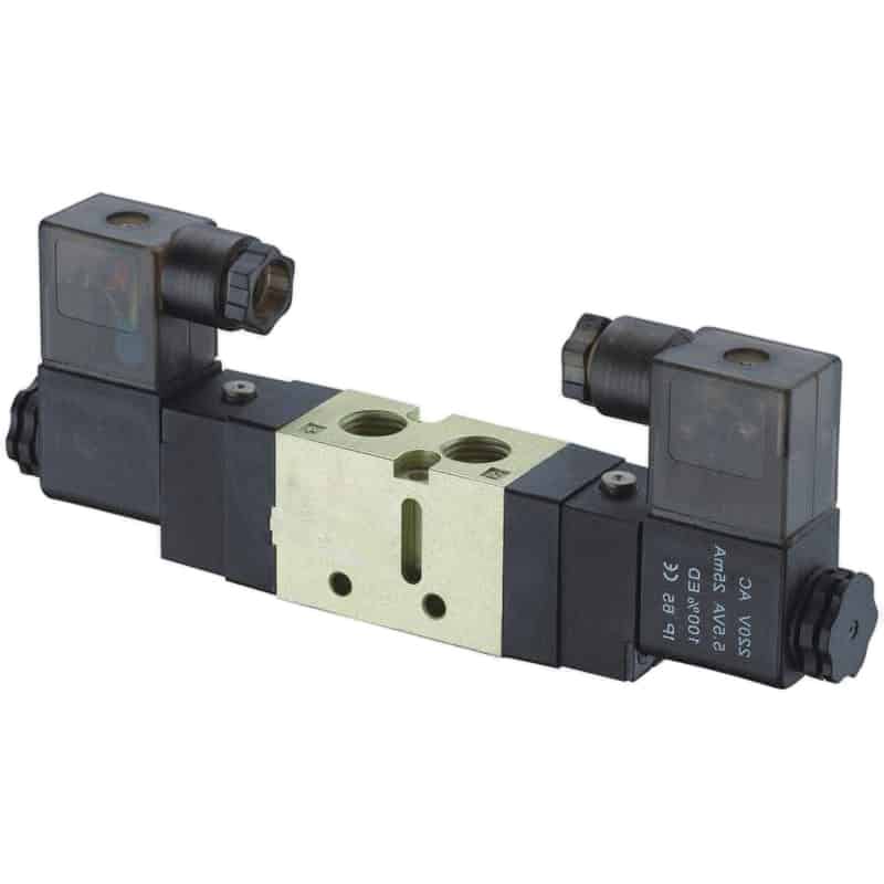
Send these details before replacing a time-critical valve:
| RFQ item | Why it matters |
|---|---|
| Coil voltage and type | AC/DC, tolerance, driver output, connector |
| Coil resistance and inductance | current ramp estimate and heat review |
| Suppression circuit | dropout delay and driver protection |
| Valve function | 3/2, 5/2, 5/3, spring return, double solenoid |
| Response target | pickup, dropout, full stroke, or sensor arrival |
| Operating pressure | pilot force, main spool shift, actuator force |
| Actuator details | bore, stroke, tube length, load, target cycle |
| Air path restrictions | muffler, flow control, manifold, fitting size |
For product context, review VF and VZ Series pneumatic directional control solenoid valves and pneumatic solenoid valves. For ambiguous timing failures, send photos, part numbers, voltage readings, cycle timing, and a short video through contact.
The best RFQ phrase is not “fast coil.” Use this instead: “valve must energize, shift, pressurize the actuator port, and reach the sensor within X ms at Y bar.” That sentence separates electrical, valve, and pneumatic delays.
Conclusion
Coil inductance affects solenoid response time because it controls how quickly current can rise or fall. The simple estimate is tau = L / R, and one time constant represents about 63.2% of the current transition.
However, the valve response that matters to production includes more than the coil. Driver design, suppression choice, spring force, pilot pressure, spool friction, flow path, exhaust, tubing, and actuator volume all add delay. Diagnose the response budget before replacing the valve.
FAQs About Coil Inductance and Solenoid Response Time
What is coil inductance in a solenoid valve?
Coil inductance is the coil’s tendency to oppose a change in current. In a solenoid valve, that means current does not jump instantly to its final value when voltage is applied. The current rise creates magnetic force, and the valve shifts only after force exceeds the mechanical and pressure loads.
Does higher inductance always mean slower solenoid response?
Higher inductance usually slows current rise for the same effective resistance and supply condition because tau = L / R. However, response also depends on pickup current threshold, driver voltage, coil resistance, spring force, friction, pilot pressure, and suppression circuit. A lower-inductance coil is not automatically better if it cannot hold reliably.
Why does a flyback diode slow solenoid release?
A flyback diode protects the driver by giving coil current a safe path when power turns off. Because the clamp voltage is low, current can decay more slowly. A TVS or zener clamp can release faster, but the higher voltage must stay within the driver, connector, and insulation ratings.
Can I reduce inductance on an existing pneumatic solenoid valve?
Usually no. Inductance is built into the winding, magnetic core, air gap, and valve design. Changing the coil is safer than modifying it. If response is still slow, check driver voltage, suppression, pilot pressure, exhaust restriction, tube length, valve Cv, and actuator load before blaming inductance alone.
Is coil response time the same as cylinder stroke time?
No. Coil response is only the electrical and electromechanical part of the event. Cylinder stroke time also includes valve shift, pressure build-up, exhaust flow, tube volume, flow controls, mufflers, actuator friction, load, and sensor placement. Separate these stages before changing coils or valves.
What should I measure when a solenoid valve responds slowly?
Measure voltage at the coil during command, coil current if possible, pressure at the valve inlet during motion, actuator port pressure, exhaust flow, and sensor arrival time. Compare pickup and dropout separately. A slow pickup often points to current or pilot force; a slow return often points to suppression, exhaust, or spring return.
Sources
- Tameson: Solenoid Valve Types, solenoid valve construction, direct-acting, indirect, and semi-direct operation. Retrieved 2026-07-08.
- RL circuit reference,
tau = L / R, exponential current response, and about 63.2% one-time-constant behavior. Retrieved 2026-07-08. - Texas Instruments: DRV110 Solenoid Current Controller Datasheet, fast current ramp-up, 50 us start-up delay, peak current, hold current, and PWM current control. Retrieved 2026-07-08.
- SMC: Control Air Flow of Cylinders, cylinder speed relationship
s = 28.8q / Aand airflow-based speed control. Retrieved 2026-07-08. - AutomationDirect: Understanding Pneumatic Valve Ports and Ways, video background for separating valve port behavior from coil response. Retrieved 2026-07-08.