

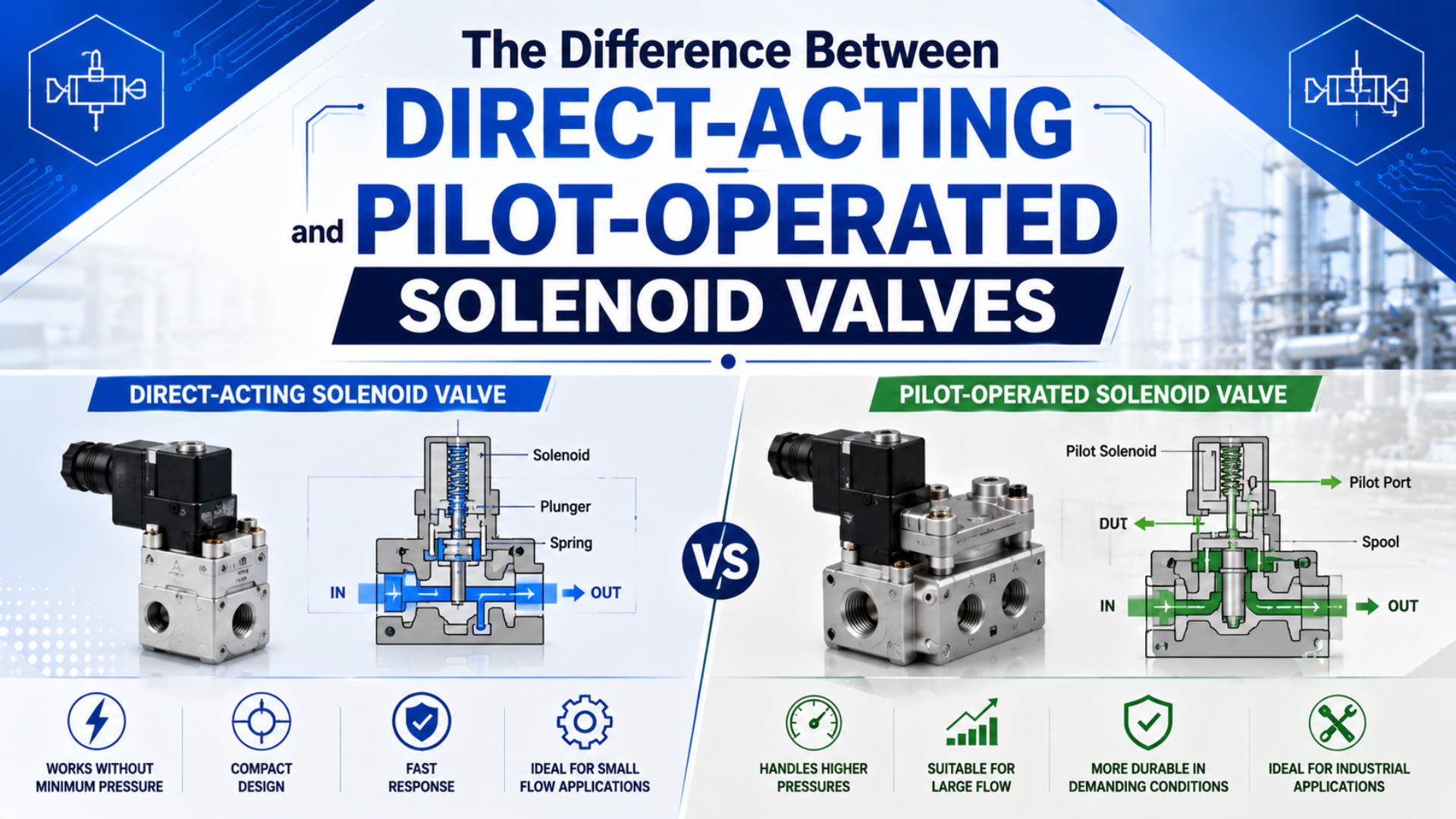
Direct-acting and pilot-operated solenoid valves differ in how they produce main-stage force. Direct action uses the coil and armature to move the sealing element itself. Pilot operation uses a small passage and fluid pressure to move a larger diaphragm, piston, or main stage. Direct action is the safer starting point for zero differential pressure, vacuum, small flow paths, or simple media circuits. Pilot operation is usually more practical when a larger nominal diameter and higher flow capacity matter, but the exact valve may need a minimum pressure differential.
Start with the pressure conditions, not the label.
This guide focuses on 2/2 on-off valves for compressed air, water, inert gas, and compatible liquids. It does not duplicate the separate guide to 3/2, 5/2, and 5/3 pneumatic solenoid valves.
Key Takeaways
- Bürkert lists its direct-acting Type 6013 up to DN 6 and its servo-assisted Type 6281 up to DN 50.
- Power consumption remains SKU-specific.
- Check differential first.
- A zero-differential or coupled-diaphragm design can bridge the gap when a standard pilot valve cannot open reliably.
Use current manufacturer product data when comparing direct-acting and pilot-operated solenoid valves; unsupported customer stories, cost percentages, and universal response-time claims should not drive selection.
What Is the Difference Between Direct-Acting and Pilot-Operated Solenoid Valves?
Bürkert describes Type 6013 as a direct-acting plunger valve up to DN 6, while Type 6281 is a servo-assisted diaphragm valve up to DN 50. Type 6013 favors a compact force path; Type 6281 uses fluid pressure to control a much larger passage (Bürkert Type 6013; Bürkert Type 6281, retrieved 2026-07-10).
That force path changes the shortlist.
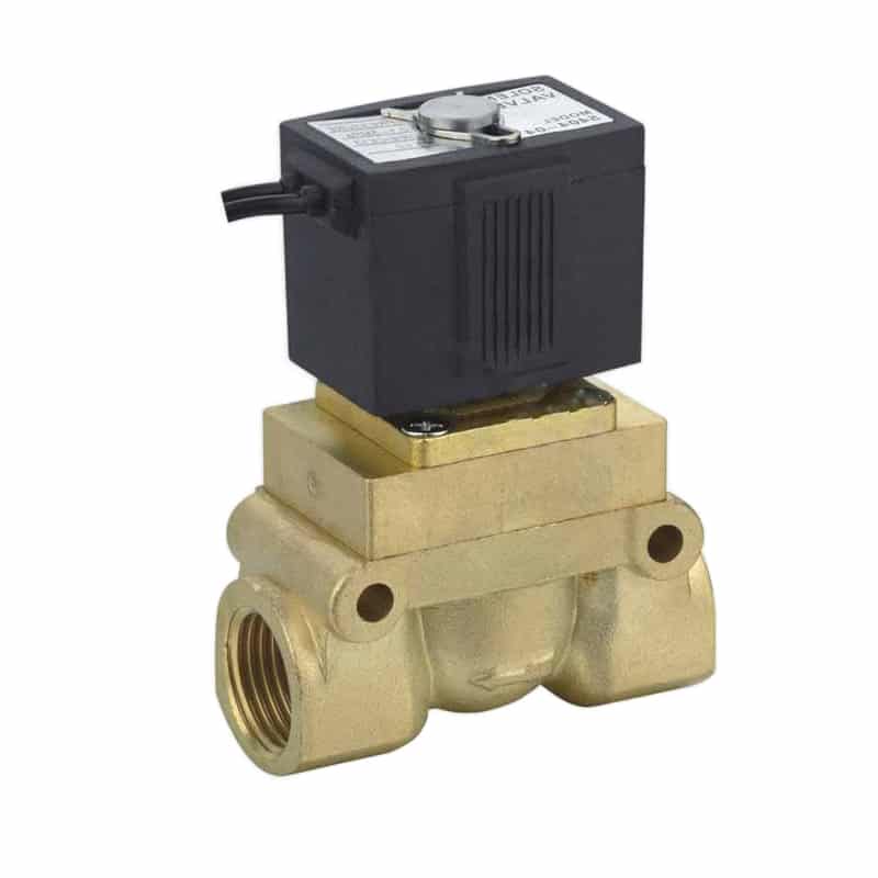
The useful distinction is where the opening force comes from:
- Direct-acting solenoid valve is a valve in which the energized coil pulls the armature and opens the main seat. It can work with zero inlet pressure when the selected construction permits it, but the coil must overcome spring force, friction, and the pressure force across the seat.
- Pilot-operated solenoid valve is a valve in which the coil opens a small pilot orifice. Line pressure moves the main stage, so a floating design needs its rated differential.
- Coupled or semi-direct: The armature is mechanically linked to the main diaphragm or piston. It can start opening at zero differential while fluid pressure assists as flow rises. Manufacturer terminology varies, so the construction drawing matters more than the marketing label.
This distinction narrows the article away from pneumatic spool-valve control. If the application is a cylinder manifold rather than a 2/2 process line, use the dedicated explanation of pilot-operated pneumatic directional valves.
How Do the Two Mechanisms Produce Opening Force?
ASCO describes a solenoid valve as 2 basic functional units: the electromagnet with its core and a valve body with one or more orifices. Its engineering guide then separates direct action from floating diaphragm or piston designs that use a pilot passage (ASCO Engineering Information, retrieved 2026-07-10).
For a normally closed direct-acting valve, the coil has to produce enough lifting force for the selected operating condition:
pressure force on the seat = pressure differential × effective seat area

available opening force > pressure force + spring force + friction
Seat area grows with the square of diameter. Doubling the effective diameter produces roughly four times the pressure-loaded area at the same differential pressure. That is why a small direct-acting orifice can carry a high pressure rating while a much larger direct seat becomes harder to lift with a practical coil.
Conventional pilot operation solves the force problem differently. Its small pilot orifice changes pressure above the diaphragm. Inlet pressure beneath the larger effective area then supplies most of the main-stage force. Electrical actuation controls the pressure balance; it does not lift the full main opening directly.
Classification labels tell you the force path, not the entire performance envelope. Small-orifice direct valves can carry high pressure. Mechanically coupled pilot valves can open at zero differential. Reading only “direct” or “pilot” hides the two dimensions that actually constrain the design: effective area and available differential pressure.
Normally Closed, Normally Open, and Fail State
Direct versus pilot operation is separate from the de-energized state. Either family can be normally closed or normally open. Specify the safe state first, then check whether the chosen construction can reach that state when pressure is lost, power is removed, or downstream pressure rises unexpectedly.
Why Does Minimum Pressure Differential Matter?
Bürkert’s servo-assisted Type 6281 always requires a minimum differential; listed 13 mm examples operate from 0.20 to 16.00 bar. By contrast, listed 13 mm Type 6213 servo-coupled versions operate from 0.00 to 10.00 bar (Bürkert Type 6281; Bürkert Type 6213, retrieved 2026-07-10).
Minimum operating pressure differential is the lowest permitted difference between inlet and outlet pressure for the main stage to open and remain stable. It is not the same as supply pressure. Supply can be 6 bar at the inlet with almost no differential when the downstream side is also near 6 bar.
Static supply pressure doesn’t answer it.
Maximum operating pressure differential (MOPD) is the greatest inlet-to-outlet difference at which the valve is rated to operate. Don’t substitute maximum static body pressure for MOPD. Body pressure can remain safe even when the selected coil and seat combination cannot switch against that load.
That distinction catches several common selection errors:
- Tank filling: Differential falls as the receiving tank approaches supply pressure. A standard servo valve may open normally at the start, slow near equalization, and fail the final part of the cycle unless the datasheet covers that low-differential state.
- Gravity-fed water: Static head may be too low to move a floating diaphragm.
- Vacuum or suction: Pressure direction and available differential may not match the pilot circuit. A direct or explicitly rated zero-differential coupled design is easier to validate before piping is built.
- Closed-loop circulation: Check differential at the valve, not pump discharge pressure.
- Blocked outlet: Trapped downstream pressure can delay closing or reopening. Record the downstream relief path and worst back-pressure condition because the same valve may behave differently during startup, normal flow, and shutdown.
For example, a tank-fill valve may see its highest differential when the vessel is empty and nearly zero differential just before equalization. Both ends of that cycle belong in the selection sheet.
ASCO makes the same construction boundary explicit. Its engineering guide says a floating diaphragm or piston needs a minimum pressure drop to remain open, while a hung-type diaphragm or piston is mechanically held open and can operate at zero pressure drop. That is a design distinction, not a brand promise.
For the physics behind this force balance, see how pressure differential creates pneumatic force. Keep the terms separate in an RFQ: inlet pressure, outlet pressure, differential pressure, and maximum operating pressure differential are four different entries.
Pressure, Orifice, and Flow: Read the Datasheet Together
Bürkert lists a 2 mm direct-acting Type 6013 configuration from 0 to 25 bar, a 13 mm servo-coupled Type 6213 from 0 to 10 bar, and a 13 mm servo-assisted Type 6281 from 0.20 to 16 bar. Orifice size changes the comparison (Bürkert, retrieved 2026-07-10).
Port thread is not a flow rating. Two valves with the same 1/2 inch connection can have different seat diameters, internal passages, Cv or Kv values, pressure limits, and media approvals. Start with the required flow and allowable pressure loss, then use connection size as a piping compatibility check.
Port size alone proves nothing.
Flow coefficient Cv is a comparative measure of a valve’s flow capacity at a defined pressure-drop relationship. It is not the port diameter. Use the manufacturer value for the exact medium and SKU, then confirm whether the supplier reports Cv, Kv, or a standardized pneumatic-flow parameter.
Cross-border RFQs should show pressure in both bar and kPa when supplier documents mix units. NIST lists 1 bar = 100 kPa = 0.1 MPa, which prevents a decimal or unit-label error from becoming a valve-selection error (NIST Guide to the SI, retrieved 2026-07-10).
This calculator helps with one part of the selection. It cannot decide minimum differential pressure, seal chemistry, water-hammer risk, coil temperature, or fail state. Readers needing a deeper explanation can use the guide to flow coefficient Cv and pneumatic valve sizing.
A Better Comparison Table
| Selection variable | Direct acting | Conventional pilot operated | Coupled or semi-direct |
|---|---|---|---|
| Zero differential | Commonly available; verify exact SKU | Often unavailable | Often available by mechanical coupling |
| Main opening force | Coil and armature | Fluid differential across diaphragm or piston | Coil starts motion; fluid assists |
| Practical passage size | Usually smaller for a given coil and pressure | Larger passages are practical | Middle ground, model dependent |
| Small pilot passages | None in the main opening mechanism | Present and contamination-sensitive | Present in many designs |
| Vacuum or equalized pressure | Often easier to specify | Requires a rated construction | Possible when the data sheet says zero differential |
| Selection document | Orifice, MOPD, coil force, media | Minimum differential, Cv/Kv, pilot path, media | Zero-differential range, coupling, Cv/Kv, media |
Current Bürkert and ASCO product pages show two practical patterns: larger servo-assisted families can reach DN 40 to DN 50, while small direct-acting configurations can still carry high pressure ratings. The missing variable in many generic comparisons is orifice size.
Which Design Fits Air, Water, Vacuum, or Contaminated Media?
ASCO lists one Series 262 direct-acting 2/2 valve at Cv 0.35 with air, inert gas, water, and light-oil service. Its specific SCE210 pilot-operated 2/2 example lists Cv 3.93 for air, inert gas, and water. Media approval and flow data are SKU-specific (ASCO 262; ASCO SCE210, retrieved 2026-07-10).
Media decides the weak point.
Compressed Air and Inert Gas
For a small shutoff, sampling line, vacuum break, or pilot signal, direct action is easy to reason about because it does not depend on line pressure to move a main diaphragm. Larger air lines may favor a pilot or coupled design, but check the lowest pressure during actual flow. Static gauge pressure can look healthy while the valve inlet collapses during demand.
Water and Compatible Liquids
Water service adds density, closing speed, trapped pressure, and water-hammer risk. Pilot-operated diaphragms can pass more flow through a compact coil package, but fast closing may produce a pressure surge. Confirm the manufacturer’s closing-time options, mounting direction, diaphragm material, and allowable back pressure.
Vacuum and Near-Zero Differential
Vacuum service is not a safe place for assumptions. Direct-acting and explicitly rated zero-differential designs are the normal starting points. Bürkert’s Type 6213 description separates a standard liquid variant that needs minimum differential from a special gas and vacuum variant that opens without it. The suffix or option code decides the behavior.
Dirty, Viscous, or Crystallizing Media
Small pilot orifices can clog before the main passage looks restricted. Direct action removes that pilot circuit, but it does not make every valve suitable for particles or viscous fluid. Seat geometry, filtration, diaphragm clearance, viscosity rating, and cleaning method still govern. If contamination is expected, put particle size and concentration in the RFQ instead of writing “dirty air.”
For compressed-air contamination classes, connect the valve specification to the guide on ISO compressed-air quality requirements. The purity class has to match both the process and the smallest valve passage.
Power and Response Are Product Data, Not Category Truths
Those ASCO examples overturn another shortcut. Series 262’s cited direct-acting SKU lists 6.1 W, while the SCE210 pilot-operated SKU lists 10.5 W. Those figures do not prove direct action is always lower power; they prove that valve size, coil design, voltage, duty, and construction must be compared at SKU level.
Bürkert offers kick-and-drop coil options on both Type 6013 direct and Type 6213 or 6281 servo-assisted families. Kick-and-drop coils can use higher power to shift and lower holding power afterward. Ask for inrush, holding power, duty cycle, coil temperature class, and suppression electronics separately.
Power labels are shortcuts, not evidence.
ISO 12238:2023 specifies procedures for measuring shifting time on electrically or pneumatically operated directional valves with 2- or 3-position functions. It does not publish a universal response-time range for direct or pilot categories (ISO 12238:2023, 2023). Compare response values only when the test definition and operating conditions are compatible.
Electrical watts are rarely the dominant lifecycle cost in a small on-off valve. Chattering from low differential, leakage from incompatible seals, or restricted flow from an undersized Cv can cost more in downtime and compressed-air loss than the coil saves. First make the valve stable. Then optimize holding power.
Selection and RFQ Checklist
Bürkert lists Type 6013 direct-acting variants with 2 to 4 mm orifices across the cited configurations, while Type 6281 listings include 13 and 20 mm servo-assisted passages. An RFQ that states only “G1/2 solenoid valve” omits the internal dimension that controls force and flow (Bürkert, retrieved 2026-07-10).
Use this decision order:
- Define the fluid. Name compressed air, inert gas, water, oil, steam, vacuum, or the exact chemical. Include concentration, viscosity, particle content, and cleaning fluid where applicable.
- State the pressure envelope. Record minimum and maximum inlet pressure, downstream pressure, available differential during opening, back pressure, and any vacuum condition.
- Calculate the required flow. Give normal and peak flow, allowable pressure drop, Cv or Kv target, and the operating temperature used for the calculation.
- Choose the force architecture. Use direct action when zero differential, simplicity, or a small passage dominates. Use standard pilot operation when a stable differential and larger flow path are available. Choose a coupled design when both zero differential and higher flow matter.
- Set the safe state. Specify normally closed or normally open, response on power loss, trapped-pressure behavior, and whether manual override is allowed.
- Complete the electrical data. Supply voltage and frequency, AC or DC, connector, inrush and holding power, duty cycle, surge suppression, enclosure, and hazardous-area approval all belong on the sheet.
- Define acceptance tests. Include leakage class, flow or Cv, opening and closing time, minimum differential, coil temperature, cycle count, and the media used during testing.
| RFQ field | What the supplier needs |
|---|---|
| Valve function | 2/2 NC, 2/2 NO, bidirectional if required |
| Operating principle | Direct, conventional pilot, or zero-differential coupled |
| Pressure data | Inlet minimum/maximum, outlet range, differential range, back pressure |
| Flow requirement | Medium, normal/peak flow, Cv or Kv, acceptable pressure loss |
| Internal passage | Required orifice or manufacturer-selected passage with calculation |
| Materials | Body, seat, diaphragm, seals, wetted metals, compliance needs |
| Electrical | Voltage, frequency, power limits, duty, connector, protection |
| Environment | Ambient/fluid temperature, washdown, vibration, dust, hazardous area |
| Verification | Leakage, response, pressure, flow, and endurance acceptance method |
Four missing numbers expose a weak quotation: minimum differential pressure, orifice, Cv or Kv, and coil holding power. Port size and maximum pressure can both match while the valve still fails the actual duty. Those values show whether the supplier selected a construction or merely matched a thread.
FAQ About Direct-Acting and Pilot-Operated Solenoid Valves
Bürkert’s published range includes a direct Type 6013 up to DN 6, a servo-coupled Type 6213 up to DN 40, and a servo-assisted Type 6281 up to DN 50. This FAQ keeps those family examples separate from universal rules and answers the five selection questions most likely to cause a wrong order.
Do pilot-operated solenoid valves always need minimum pressure differential?
No. Conventional floating diaphragm or piston designs usually need a rated differential, and Bürkert lists Type 6281 examples from 0.20 bar. Coupled designs can be different: listed Type 6213 configurations start at 0.00 bar. Check the exact construction and suffix instead of treating “pilot-operated” as one hydraulic design.
Are direct-acting solenoid valves only suitable for low pressure?
No. Pressure capacity also depends on orifice area and coil force. Bürkert lists a 2 mm Type 6013 direct-acting configuration from 0 to 25 bar, while 4 mm configurations have lower listed maxima. Small high-pressure direct valves may still have far less flow than a larger servo-assisted design.
Do pilot-operated valves always consume less electrical power?
No. One ASCO Series 262 direct-acting SKU lists 6.1 W, while the cited SCE210 pilot-operated SKU lists 10.5 W. Coil technology, voltage, size, inrush, holding power, and duty cycle change the result. Compare equivalent product data instead of assigning one wattage range to an entire operating principle.
Which type responds faster?
Direct action often removes the delay of filling or venting a pilot chamber, but a universal millisecond range is not defensible. ISO 12238:2023 defines a measurement procedure for 2- and 3-position directional valves. Compare supplier response data only when pressure, temperature, voltage, medium, test circuit, and shifting-time definition match.
What information is most important when sizing a solenoid valve?
Start with medium, inlet and outlet pressure, minimum differential, normal and peak flow, allowable pressure drop, and temperature. Then confirm orifice, Cv or Kv, seal materials, fail state, voltage, duty cycle, and response method. Connections such as G1/2 or 1/2 inch identify the port, not the internal flow capacity.