

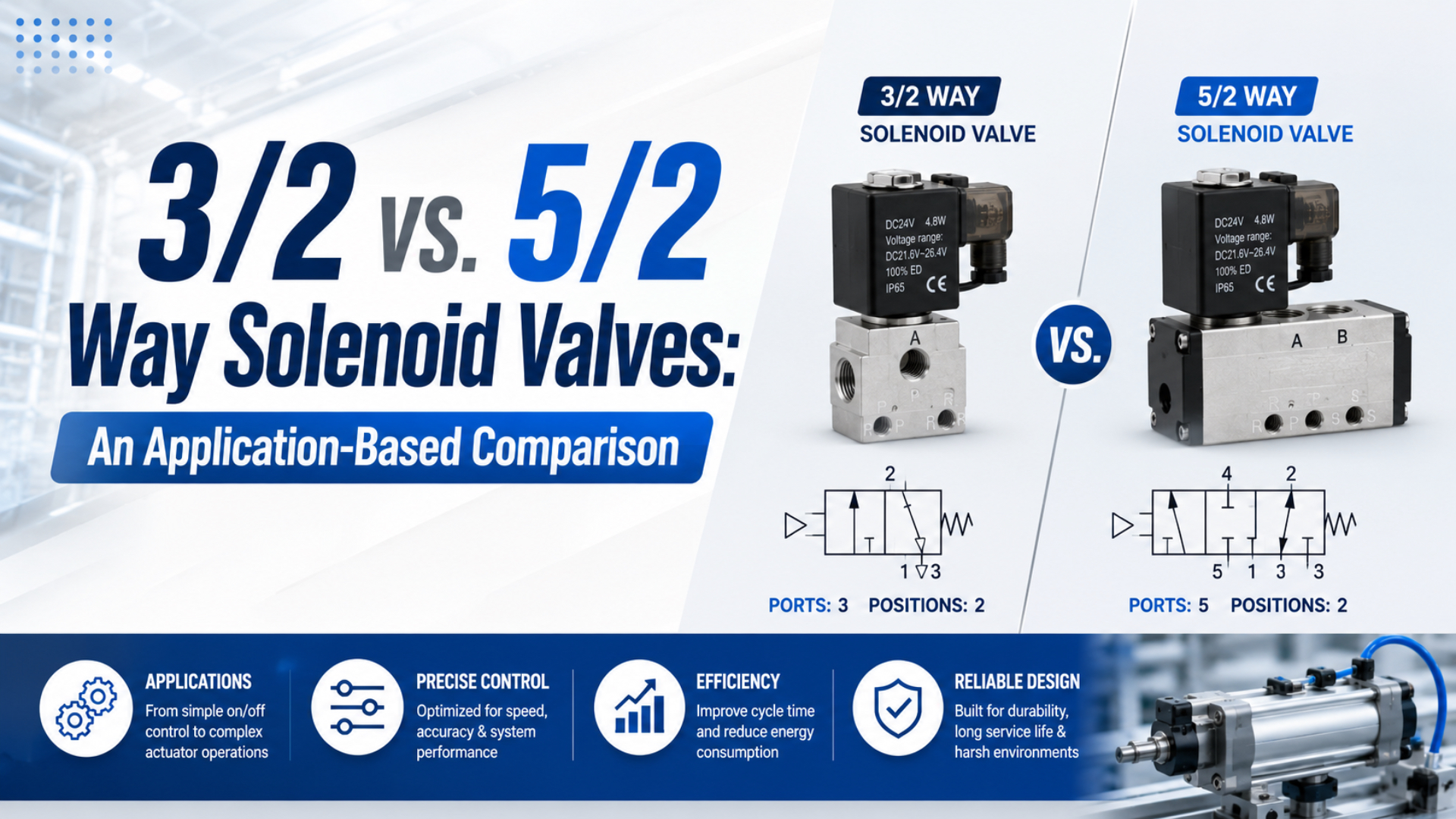
A 3/2 solenoid valve has three ports and two positions, making it the usual choice for a single pneumatic work port. A 5/2 valve has five ports and two positions, so it can alternately pressurize the two work ports of a double-acting actuator. The 3/2 vs. 5/2 way solenoid valves comparison starts there, not with perceived complexity.
Key Takeaways
- Use 3/2 for one controlled work port and 5/2 for two alternately pressurized work ports.
- ISO 15407 covers 18 mm and 26 mm five-port interfaces up to 1.6 MPa, but not functional equivalence.
- Select the normal and failure states before selecting coil or manifold options.
- Size flow and exhaust from the actuator’s required stroke time.
Short Answer: Match the Valve to the Required Circuit States
ISO 11727:1999 was reviewed and confirmed current in 2026 and defines rules for identifying directional-valve ports, pilot connections, solenoid leads, and control mechanisms (ISO 11727, 1999). Apply those markings to a state table before choosing a 3/2 or 5/2 valve.
Use these five decisions:
- How many actuator or process work ports must the valve control?
- Which path must be open in the normal, energized, and de-energized states?
- What should happen after loss of electrical power, pilot pressure, or main air?
- What flow and exhaust capacity are required for the target motion time?
- Does the proposed valve fit the manifold, connector, safety architecture, and maintenance procedure?
Valve notation means ports/positions. A 3/2 valve has three controlled pneumatic ports and two switching positions. A 5/2 valve has five ports and two positions. Solenoid count, spool design, pilot method, and failure state are separate properties.
The better selection question is not “Which valve has more capability?” It is “Which valve creates every required circuit state without adding an unused path, an unsafe retained state, or a flow restriction?” This keeps the decision tied to machine behavior rather than component count.
What Does a 3/2 Solenoid Valve Control?
ISO 1219-1:2012 is a 178-page, third-edition standard for fluid-power graphical symbols, while ISO 1219-2 supplies the circuit-diagram rules (ISO 1219-1, 2012; ISO 1219-2, 2012). Read both positions of a 3/2 symbol before assuming its normal state during circuit selection and commissioning.
A 3/2 solenoid valve is a two-position directional valve with supply, work, and exhaust ports for one controlled pneumatic path.
A 3/2 valve usually has:
- port 1 for pressure supply
- port 2 for the work connection
- port 3 for exhaust
The two positions determine whether port 2 is connected to supply, exhaust, or blocked. A normally closed 3/2 valve commonly blocks supply and exhausts the work port when de-energized. A normally open version does the opposite. Product symbols and datasheets remain the authority.
One 3/2 valve naturally matches a single-acting cylinder because the actuator has one pneumatic port. The valve pressurizes that port for the powered stroke and exhausts it for spring or external-load return. The same valve format can also control an air pilot, vacuum ejector, blow-off nozzle, process-air signal, or other one-path function.
Do not equate “single-acting” with “safe.” A spring-return actuator may move when pressure is released, and that movement can be hazardous. The circuit needs a defined safe state, load assessment, guarding, isolation, and verification. See the single-acting versus double-acting cylinder guide for the actuator-side comparison.
What Does a 5/2 Solenoid Valve Control?
ISO 15407-1 applies to five-port directional-valve mounting interfaces in 18 mm and 26 mm sizes at working pressures up to 1.6 MPa, or 16 bar (ISO 15407-1, 2000). The standard covers the interface, not the valve’s functional performance or application suitability.
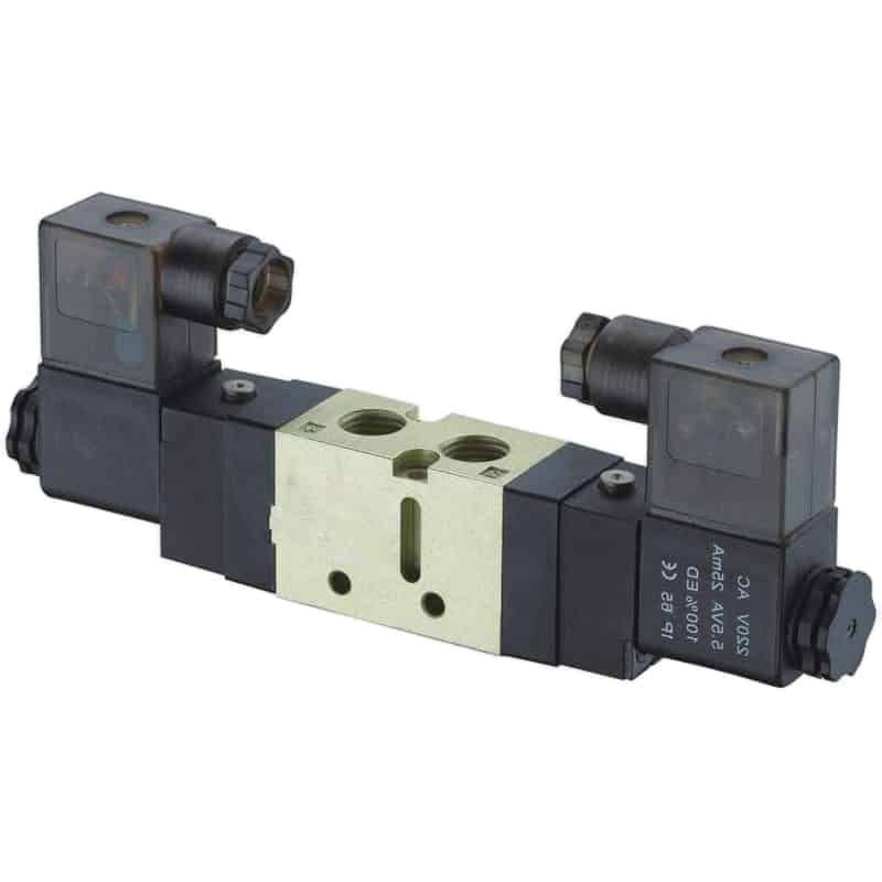
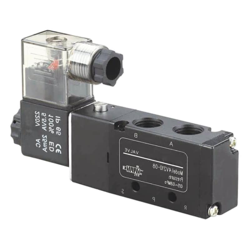
A 5/2 solenoid valve is a two-position directional valve with one supply, two work ports, and two exhaust ports for alternating chamber control.
A 5/2 valve usually has:
- port 1 for pressure supply
- ports 2 and 4 for the two actuator work connections
- ports 3 and 5 for the two exhaust paths
In one position, supply connects to one work port while the other work port exhausts. The second position reverses those paths. This matches a double-acting cylinder because one chamber is pressurized while the opposite chamber is vented.
Two exhaust ports allow each cylinder direction to have its own meter-out control, silencer, or exhaust path. That can help tune extend and retract speeds separately. It does not guarantee precise positioning. A standard 5/2 valve commands two end-to-end directions, not closed-loop intermediate position.
A 5/2 valve can be monostable or bistable. A monostable single-solenoid design normally uses a spring or pneumatic return. A double-solenoid bistable design may retain its last position after electrical power is removed. Confirm the exact symbol and restart behavior before treating either design as a replacement.
For other internal design choices, separate port configuration from spool versus poppet valve architecture and direct versus pilot-operated solenoid valves.
How Do 3/2 vs. 5/2 Way Solenoid Valves Map to Actuator States?
Festo’s VSNC range includes switchable 3/2 or 5/2 single-solenoid configurations with published 24 V DC coil power of 0.7 W and switching times that vary by configuration (Festo VSNC data, 2026). One product family therefore demonstrates that valve function and measured behavior must be checked separately.
| Required machine function | Typical starting valve | Normal-state question | Important exception |
|---|---|---|---|
| Single-acting cylinder, powered extension | 3/2 NC | Should loss of power exhaust the cylinder? | Spring or load return can still create hazardous motion |
| Single-acting cylinder, pressure held normally | 3/2 NO or engineered circuit | Should de-energizing maintain pressure? | Check restart and trapped-energy behavior |
| Double-acting cylinder, spring return valve | 5/2 monostable | Which cylinder port receives pressure when power is lost? | Spring-return spool state may move the actuator |
| Double-acting cylinder, retained command | 5/2 bistable | Is the last position acceptable after power loss? | Electrical reset does not guarantee pneumatic reset |
| Double-acting cylinder with center state | 5/3, not 5/2 | Should the center block, exhaust, or pressurize ports? | Center state does not create precision positioning by itself |
| Independent pneumatic signals | Multiple 3/2 valves | Does each output need its own normal state? | Two 3/2 valves can control a double-acting actuator, but logic and safety change |
For example, a packaging clamp may use a 3/2 valve if one chamber is pressurized and a spring opens the clamp. A transfer cylinder usually starts with a 5/2 valve because both chambers need controlled pressure and exhaust. The final choice still depends on the required power-loss state.
Count required states before counting ports. Two independent 3/2 valves can create more command combinations than one 5/2 valve, but they also introduce coordination, crossover, and fault-state questions. More combinations are useful only when the control architecture explicitly needs and validates them.
How Should Power Loss and Safety Affect the Choice?
ISO 13849-1:2023 is the fourth edition of the machinery-control safety standard and applies to electrical, hydraulic, pneumatic, and mechanical safety-related control systems (ISO 13849-1, 2023). It does not prescribe one valve function or Performance Level for every application or machine risk.
Neither 3/2 nor 5/2 is inherently fail-safe. Safety comes from the complete safety function: risk assessment, required state, architecture, component suitability, diagnostic coverage, resistance to common-cause failure, validation, and maintenance. A normal position that is safe for one machine can be dangerous for another.
Review at least these events:
| Event | Circuit question |
|---|---|
| Solenoid power lost | Which work ports connect to supply, exhaust, or block? |
| PLC or fieldbus restarts | Is an unexpected output pulse or retained command possible? |
| Main air lost | Can gravity, springs, or external loads move the actuator? |
| Pilot pressure lost | Does the main spool return, remain, or shift incompletely? |
| Exhaust blocked | Can backpressure prevent the expected safe state? |
| Air restored | Does the machine restart or move before a deliberate reset? |
OSHA 29 CFR 1910.147 identifies pneumatic pressure as an energy source and states that push buttons and selector switches are not energy-isolating devices (OSHA 1910.147, accessed 2026). A control valve command does not replace a lockable supply isolation and residual-pressure release procedure.
Safety exhaust, redundant valves, pressure monitoring, load-holding devices, or mechanical blocks may be required. Select these from the machine’s risk reduction plan. Do not infer a safety rating from port count, spring return, or a marketing description such as “fail-safe.”
How Do Flow, Exhaust, and Stroke Time Change the Decision?
ISO 6358-1:2013 defines steady-state testing of pneumatic components with compressible fluids, and its six-page Amendment 2 was published in April 2026 to address measurement uncertainty (ISO 6358-1, 2013; Amendment 2, 2026). Compare flow data only under compatible reference conditions during valve selection.
Port count does not define flow capacity. A compact 5/2 valve can be more restrictive than a larger 3/2 valve, while a fast 5/2 design can switch much faster than a general-purpose 3/2 valve. Use manufacturer sonic conductance, critical pressure ratio, Cv, Kv, standardized flow, and pressure-drop curves.
The cylinder also changes the answer. A double-acting cylinder consumes compressed air in both powered directions. A single-acting cylinder uses compressed air for one powered chamber, but spring force reduces available output and the return stroke still needs adequate exhaust. Compare complete cycle demand rather than assuming one valve type always saves air.
Check the entire path:
- supply pressure measured dynamically at the valve inlet
- valve flow rating and test convention
- fitting and tube inside diameter
- tube length and bends
- meter-out controls, quick exhaust valves, and silencers
- shared manifold supply and exhaust galleries
- cylinder bore, rod area, stroke, load, and cushion setting
If speed tuning is part of the application, use the separate meter-in versus meter-out flow-control guide. A 5/2 valve’s separate exhaust paths can simplify directional meter-out adjustment, but the flow controls still determine the restriction.
Which Applications Fit Each Valve Type?
SMC lists one three-port valve family with response speed of 10 ms or less, while a Festo fast-switching 5/2 family lists approximately 1.7 ms off and 1.9 ms on for a 100 L/min configuration (SMC VV061 data, 2026; Festo MH fast-switching valves, accessed 2026). Product design matters more than port count.
| Application | Likely starting point | Selection reason | Verify before release |
|---|---|---|---|
| Spring-return clamp | 3/2 | One pneumatic work port | Safe release direction, spring force, trapped load |
| Air blow or pilot signal | 3/2 | One controlled supply/exhaust path | Normally open/closed state, flow, noise |
| Double-acting transfer cylinder | 5/2 | Two alternately powered chambers | Stroke time, meter-out settings, power-loss state |
| Bistable indexing motion | 5/2 double solenoid | Command may be retained | Reset sequence and behavior after air loss |
| Intermediate center requirement | 5/3 or another architecture | A center state is required | Center function, leakage, drift, load holding |
| Safety-related exhaust | Validated safety architecture | Port count alone is insufficient | PLr, diagnostics, redundancy, isolation, validation |
Do not use “positioning” as shorthand for a 5/2 advantage. A two-position valve is well suited to end-to-end cylinder motion. Repeatable intermediate positioning normally needs sensing, proportional or servo control, a brake or lock, and a defined control strategy.
The related solenoid-valve working-principle guide covers general construction. For replacement work, use the OEM solenoid-valve compatibility checklist after the circuit function is chosen.
Lifecycle Cost Inputs, Not Universal Price Percentages
OSHA requires covered energy-control procedures to receive a periodic inspection at least annually, which makes isolation, documentation, and maintenance part of lifecycle cost rather than optional extras (OSHA 1910.147, accessed 2026). No universal 20% to 40% price gap applies across valve sizes, brands, coils, and manifolds.
Build the comparison from quoted and measured inputs:
| Cost input | 3/2 option | 5/2 option | Evidence |
|---|---|---|---|
| Valve and coil | Supplier quotation | Supplier quotation | Exact part codes and validity date |
| Manifold and fittings | Port count, base, silencers | Port count, base, silencers | Bill of materials |
| Installation | Tube runs, wiring, programming | Tube runs, wiring, programming | Estimated labor and change scope |
| Compressed air | Chamber volume and cycles | Both chamber volumes and cycles | Calculated demand and measured pressure |
| Maintenance | Spare count, access, contamination controls | Spare count, access, contamination controls | Service plan and failure history |
| Downtime risk | Defined normal and failure state | Defined normal and failure state | Machine risk and acceptance tests |
A 3/2 valve is often simpler for a one-port function. That does not prove lower total cost if the spring-return actuator needs more size, the safe state needs extra hardware, or the circuit requires two coordinated 3/2 valves. Likewise, a 5/2 valve’s extra ports are valuable only when the application uses them.
Cost follows required states. The cheapest valve body can create the most expensive circuit when adapters, extra logic, restricted exhaust, or an unsuitable failure state must be corrected elsewhere. Compare the controlled system boundary, not isolated catalog prices.
FAQs About 3/2 vs. 5/2 Solenoid Valves
ISO 12238:2023 is a 17-page, second-edition standard for measuring shifting time in monostable and bistable pneumatic directional valves with two or three positions (ISO 12238, 2023). This reinforces why FAQ answers must separate valve topology from product-specific performance in practice.
Can a 5/2 valve control a single-acting cylinder?
It may be possible with a manufacturer-approved circuit, but it is rarely the default choice. Do not plug or vent an unused work port by habit. Check every spool position, exhaust path, leakage route, restart state, and manifold rule. A correctly selected 3/2 valve usually expresses the one-port function more clearly.
Can a 3/2 valve control a double-acting cylinder?
One 3/2 valve cannot alternately pressurize and exhaust both chambers. Two coordinated 3/2 valves can control a double-acting cylinder, but they create additional command combinations and fault states. Use that architecture only when independent chamber control is intentional and the control and safety logic are validated.
Is a 3/2 valve always faster than a 5/2 valve?
No. Published examples range from 10 ms or less for one SMC three-port family to about 1.7 ms off and 1.9 ms on for one Festo fast-switching 5/2 family. Compare exact models under stated pressure, voltage, temperature, and test methods rather than inferring speed from port count.
Which valve is safer after loss of power?
Neither topology is automatically safer. The answer depends on the complete symbol, spring or bistable behavior, actuator load, gravity, trapped pressure, exhaust path, restart logic, diagnostics, and required Performance Level. Define the safe machine state first, then validate the complete safety function.
Does a 3/2 valve always consume less air?
No. A single-acting cylinder normally consumes compressed air in one powered chamber, while a double-acting cylinder consumes air in both directions. Actual demand depends on bore, rod area, stroke, pressure, dead volume, cycles, leakage, and exhaust strategy. Calculate the complete cycle before comparing operating cost.
Conclusion
ISO 11727 was confirmed current in 2026, while ISO 15407 remains limited to defined five-port interfaces and does not establish functional equivalence (ISO 11727, 1999; ISO 15407-1, 2000). Select 3/2 or 5/2 from required circuit states, not perceived complexity alone.
Source Notes
- ISO, ISO 11727:1999. Retrieved July 11, 2026. https://www.iso.org/standard/19651.html
- ISO, ISO 1219-1:2012. Retrieved July 11, 2026. https://www.iso.org/cms/%20render/live/en/sites/isoorg/contents/data/standard/06/01/60184.html
- ISO, ISO 1219-2:2012. Retrieved July 11, 2026. https://www.iso.org/standard/51200.html
- ISO, ISO 15407-1:2000. Retrieved July 11, 2026. https://www.iso.org/standard/27625.html
- ISO, ISO 13849-1:2023. Retrieved July 11, 2026. https://www.iso.org/standard/73481.html
- ISO, ISO 6358-1:2013 and Amendment 2:2026. Retrieved July 11, 2026. https://www.iso.org/standard/56612.html
- ISO, ISO 12238:2023. Retrieved July 11, 2026. https://www.iso.org/standard/77084.html
- OSHA, 29 CFR 1910.147. Retrieved July 11, 2026. https://www.osha.gov/laws-regs/regulations/standardnumber/1910/1910.147
- Festo, VSNC Solenoid Valve Technical Data. Retrieved July 11, 2026. https://media.festo.com/media/203907_documentation.pdf
- Festo, MH Fast-Switching Valves. Retrieved July 11, 2026. https://ftp.festo.com/Public/PNEUMATIC/SOFTWARE_SERVICE/Documentation/2006/EN/FAST-SWITCHING-VALVES_EN.PDF
- SMC, VV061 Three-Port Solenoid Valve Data. Retrieved July 11, 2026. https://www.smcworld.com/catalog/BEST-5-1-en/pdf/1-p1881-1889-vv061_en.pdf