

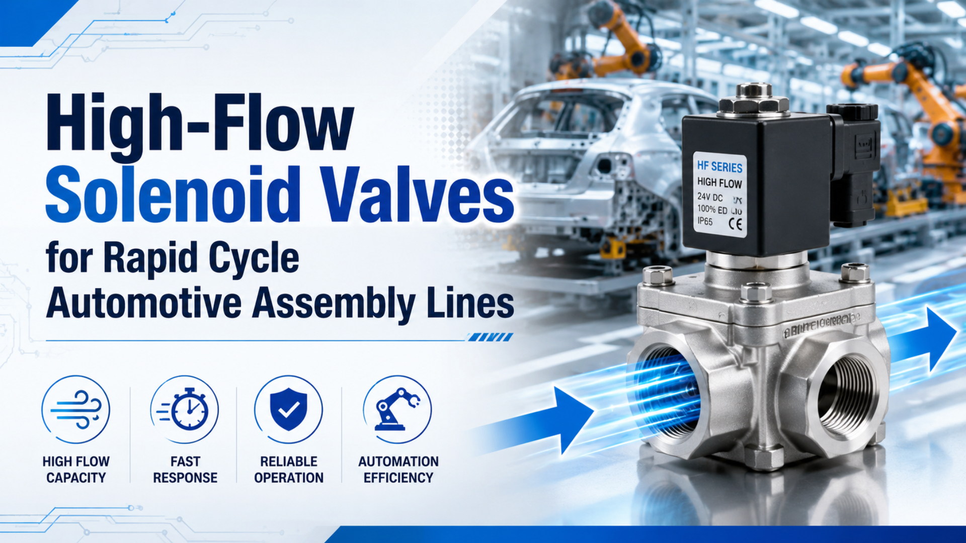
A high-flow solenoid valve helps an automotive assembly station only when the directional valve is the measured restriction. Rated flow alone cannot prove a shorter cylinder stroke, higher line throughput, lower air consumption, or acceptable machine timing. The complete supply and exhaust path has to support the required motion under the real production load.
Start with the station event: clamp, locate, lift, transfer, press, reject, or release. Define load, cylinder bore, stroke, working pressure, target time, acceptable impact, and sensor threshold. Then calculate the required flow and test where pressure and time are being lost. That sequence separates a valve problem from a tube, fitting, muffler, regulator, receiver, or mechanical problem.
Key Takeaways
- Parker’s worked example requires Cv 1.06 for a 3.25-inch bore cylinder completing a 12-inch stroke in one second.
- ISO 6358 flow data and ISO 12238 shifting time answer different questions.
- Check supply and exhaust together.
- Prove throughput at the bottleneck station, not from valve flow alone.
High-flow solenoid valve sizing is the process of matching a directional valve’s supply and exhaust capacity to a cylinder’s required stroke time while preserving force, control, cushioning, safety, and repeatability. It is not the selection of the largest port or highest catalog L/min value.
What Flow Does the Actuator Need for the Target Stroke Time?
Parker’s engineering example uses a 3.25-inch bore, 12-inch stroke, 80 psig supply, and one-second extension to calculate a required Cv of 1.06 (Parker Pneumatic Valve Engineering Data, 2026). The method begins with motion demand, not a 2,000 L/min marketing threshold.
Parker’s 80 psig example shows why a high-flow valve must be tied to an allowed pressure loss. Its sizing table uses a compression factor of 6.4 and an A constant of 0.048 for a 5 psi pressure drop; combined with an 8.30 square-inch piston area, 12-inch stroke, and one-second target, the result is Cv 1.06. That value is a minimum checkpoint for the stated motion, not a universal automotive valve size. Changing the cylinder area, stroke time, supply pressure, or allowed pressure drop changes the result. The selected catalog valve must then be checked in both supply and exhaust directions, because fittings, tubing, flow controls, manifold galleries, and silencers can consume the remaining pressure budget even when the valve body meets Cv 1.06 (Parker, 2026).
The sizing chain should stay in this order:
- Determine force from load, motion direction, pressure, friction, and safety margin.
- Select cylinder bore from force demand, not from desired speed.
- Record bore, rod diameter, stroke, working pressure, and target extension and retraction times.
- Calculate the free-air flow needed during each stroke.
- Select valve capacity for the allowed dynamic pressure loss.
- Verify tubing, fittings, flow controls, cushions, manifold passages, and exhaust hardware.
SMC expresses the basic speed relationship as s = 28.8q / A, where s is cylinder speed in inches per second, q is flow in SCFM, and A is piston area in square inches (SMC, Control Air Flow of Cylinders, 2026). SMC also states that inlet pressure must remain constant and that ports and tubing affect the result.
That caveat matters. Doubling a catalog flow rating does not guarantee twice the installed speed. Pressure can sag during motion. The exhaust side may be smaller than the supply side. A meter-out controller, fitting, or muffler may become the dominant restriction. The cylinder may also reach its cushion before the theoretical constant-speed portion ends.
What about cylinder size? Higher valve capacity can help a correctly sized cylinder reach its target time, but it does not reduce the force requirement. Replacing a large cylinder with a smaller one is valid only when a new load and pressure calculation proves that the smaller bore still has enough force and stability.
Required stroke flow is a short-duration motion requirement, while cycle-average air consumption is a repeated-use requirement. The valve path must pass the first. The compressor and receiver must support the second. Confusing them can produce a station with adequate average compressor capacity but an unacceptable pressure dip during a 300 ms motion.
The broader pneumatic flow control valve sizing guide contains the full calculation sequence. This article stays focused on applying that sequence to a rapid-cycle automotive station.
When Is the Directional Valve Actually the Bottleneck?
ISO 12238:2023 defines shifting-time tests for electrically or pneumatically operated directional valves with two or three positions (ISO 12238:2023, 2023). Valve shifting time is only one interval; an automotive station also includes tube fill, exhaust, actuator travel, sensor confirmation, and downstream readiness.
Use four synchronized measurements before replacing the valve:
| Measurement | What it reveals |
|---|---|
| electrical command or coil voltage | when the controller requested motion |
| valve inlet pressure during the stroke | whether the local supply stays available |
| both cylinder-port pressures | supply loss, exhaust back pressure, and load response |
| actuator position or end sensor | actual machine movement and arrival |
If command-to-valve-pressure time is long while supply pressure remains stable, the coil, pilot stage, contamination, or valve mechanism deserves attention. If valve pressure changes quickly but cylinder-port pressure is late, the restriction lies between the valve and actuator. If both pressure traces are prompt but the sensor is late, inspect load, guidance, seals, cushions, and mechanics.
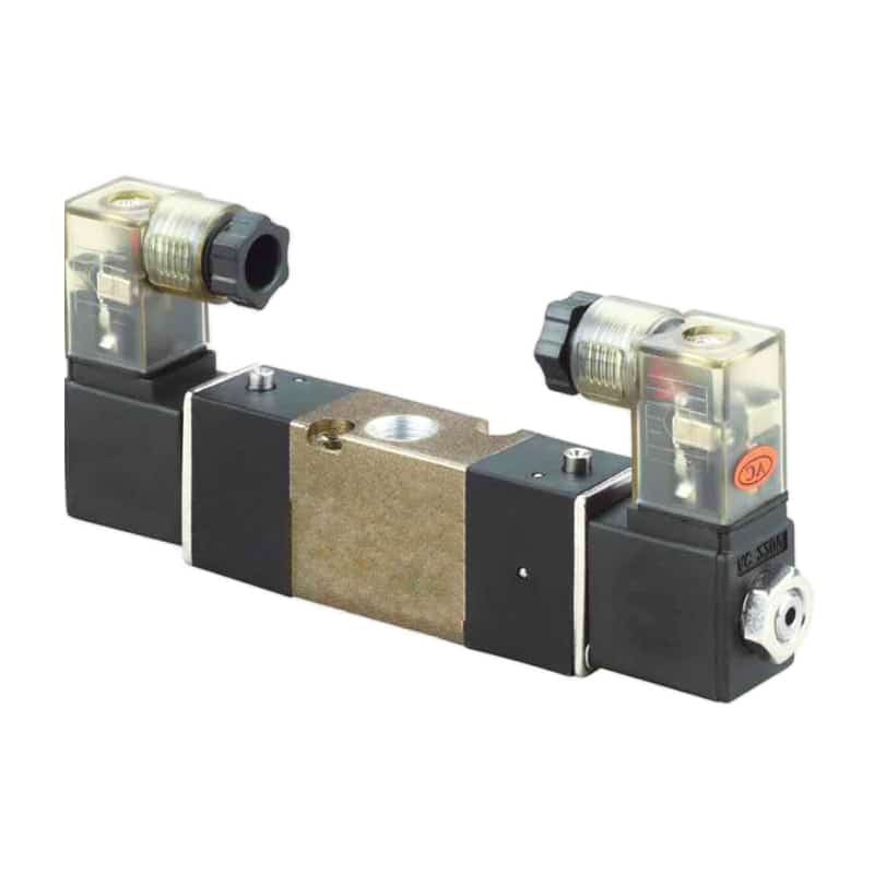
The retained product photo shows directional-valve hardware, but a photograph cannot prove flow capacity. Use the exact part number’s function, pressure range, Cv or ISO 6358 data, response test, connector, and environmental ratings before treating it as a high-flow candidate.
High inlet pressure alone is not proof. A static gauge may show 6 bar while the valve inlet falls during simultaneous demand. Likewise, removing a muffler may make the return stroke faster, revealing an exhaust restriction rather than an undersized supply passage.
A rapid-cycle complaint should be written as a time budget. “The valve is slow” is not measurable. “Command to 90% pressure at port A takes 24 ms, valve outlet to cylinder port takes 70 ms, and cylinder-port pressure to sensor arrival takes 180 ms” identifies three separate improvement opportunities.
Use the solenoid valve response-time measurement guide when the electrical and pneumatic boundaries need to be separated.
How Should High-Flow Solenoid Valves Be Compared?
ISO 6358-1:2013 is a 61-page standard for steady-state flow testing of pneumatic components using compressible fluids, and it specifies the installation, procedure, and result presentation (ISO 6358-1, amended 2026). A bare L/min number is incomplete without its test pressure, downstream condition, temperature, and reference state.
Compare the exact flow direction required by the machine. A 5/2 or 5/3 valve can have different effective capacity from pressure to working port and from working port to exhaust. A large supply rating does not guarantee a large exhaust path, especially after a manifold gallery, meter-out controller, elbow, and silencer are added.
Use one consistent catalog method:
| Data format | Use it for | Keep with the number |
|---|---|---|
| Cv | manufacturer pneumatic sizing method and model comparison | upstream and downstream pressure, temperature, flow direction |
| Kv | metric catalog comparison | conversion method and pneumatic validation |
ISO 6358 sonic conductance C and critical pressure ratio b |
compressible-flow calculation | test conditions and current standard edition |
| rated L/min or SCFM | quick comparison within one catalog family | standard conditions, supply pressure, pressure drop, direction |
Port thread is only the connection. Two G1/2 valves can have different spool diameters, pilot stages, manifold galleries, seals, and exhaust passages. Conversely, a compact valve with efficient internal geometry may outperform a larger threaded body under the same pressure conditions.
Don’t use the liquid shortcut Q / sqrt(delta P) for compressed air without the manufacturer’s pneumatic method. Gas flow depends on absolute upstream and downstream pressure, temperature, and whether the path is subcritical or choked. The companion guide to sonic conductance and critical pressure ratio explains that boundary.
Can the Plant Air System Support Simultaneous Rapid Cycles?
CAGI recommends no more than 10% pressure drop between compressor discharge and any point of use in a well-designed compressed-air system (CAGI, Working With Compressed Air, retrieved July 11, 2026). A local high-flow valve cannot correct a starved header, undersized branch, saturated filter, or restricted manifold inlet.
Peak station demand and average compressor demand are not the same. For example, four cylinders that each require 30 SCFM during a short stroke can create a 120 SCFM local event if they start together. Staggering them may reduce the instantaneous branch demand without changing the air used by each completed stroke.
Check these layers:
- compressor output and operating control range
- main and branch pipe ID, length, and material
- local receiver volume and recovery time
- filter, dryer, regulator, and soft-start capacity
- manifold inlet and exhaust gallery limits
- simultaneous motions sharing the same branch
- pressure at the valve during the worst production sequence
Raising compressor discharge pressure is not the first answer. CAGI states that every 2 psig of excess operating pressure increases positive-displacement compressor power by approximately 1% (CAGI Pressure Drop FAQ, retrieved July 11, 2026). Higher pressure can also increase unregulated demand and leakage.
Does a high-flow valve reduce air consumption? Not by itself. For a completed cylinder stroke, chamber volume and pressure dominate the theoretical air quantity. For instance, a larger valve may shorten fill and exhaust time without changing the chamber volume. If that enables more cycles per hour, total hourly air demand can rise.
The lowest-cost cycle-time improvement may be sequence control rather than hardware. If two high-demand motions do not need to start together, a small timing offset can protect point-of-use pressure and avoid oversizing every valve, branch, and receiver around one avoidable peak.
How Should an Automotive Station Pilot Be Validated?
SMC’s relation s = 28.8q / A ties cylinder speed to flow and piston area only when inlet pressure is held constant (SMC, 2026). A useful pilot must therefore record pressure, flow-path configuration, load, timing thresholds, and repeated production cycles before and after the valve change.
Choose a station where the motion limits the station cycle and where a controlled rollback is possible. Do not start with a safety-critical vertical load or a station whose downstream equipment is already the true constraint.
Station response budget is the measured sequence from controller command through valve shift, pressure change, actuator travel, sensor arrival, and downstream readiness. Each interval has a different likely cause.
Record the baseline:
- Cylinder bore, rod, stroke, load direction, cushion settings, and guide condition.
- Valve model, function, coil voltage, pilot arrangement, and flow data.
- Tube IDs and lengths, fittings, flow controls, mufflers, and manifold configuration.
- Dynamic pressure at the valve inlet and both cylinder ports.
- Command, pressure, position, and end-sensor timestamps on one time base.
- Minimum, average, maximum, and variation over repeated cycles.
- Station cycle, blocked time, and downstream readiness.
Then install the approved candidate without changing unrelated settings. Repeat the same production sequence, pressure range, load, and measurement thresholds. A faster unloaded maintenance stroke is not evidence that the production station improved.
Accept the upgrade only when all required outcomes pass:
- target extension and retraction time
- force and holding behavior at minimum pressure
- impact and cushion energy within limits
- cycle variation within the machine tolerance
- safe power-loss, air-loss, stop, and restart behavior
- no new pressure instability at adjacent stations
- measurable improvement at the actual line constraint
OSHA 1910.147 identifies pneumatic energy as a hazardous energy source and requires stored or residual energy to be made safe during servicing (OSHA 1910.147, retrieved July 11, 2026). A faster valve does not replace verified isolation, bleed-down, restraint, and restart controls.
Selection and RFQ Checklist
Parker’s Cv 1.06 example uses five linked operating inputs: cylinder area, stroke, compression factor, allowed pressure drop, and one-second stroke time (Parker, 2026). An automotive high-flow valve RFQ needs those motion inputs plus electrical, environmental, network, and safety requirements.
| RFQ field | Information to provide |
|---|---|
| machine event | clamp, lift, locate, transfer, reject, press, or release |
| actuator | bore, rod, stroke, load, orientation, cushion, required force |
| timing | extension, retraction, pressure threshold, sensor threshold, repetitions |
| valve function | 3/2, 5/2, 5/3, spring return, double solenoid, center state |
| flow data | Cv, Kv, ISO 6358 data, or rated flow with conditions for both directions |
| pressure | normal, minimum dynamic, maximum, pilot requirement, allowed drop |
| air path | FRL, manifold, tube ID and length, fittings, controls, mufflers |
| electrical | voltage, AC/DC, inrush, hold current, suppression, connector, PLC output |
| network | PROFINET, EtherNet/IP, IO-Link, diagnostics, safe outputs, approved device file |
| environment | temperature, ingress, oil, coolant, washdown, vibration, contamination |
| safety | de-energized state, trapped pressure, isolation, restart, manual override |
| validation | baseline trace, acceptance limits, production load, rollback plan |
Do not use IP65 or IP67 as shorthand for every automotive exposure. IEC 60529 ingress ratings address enclosure protection against solids and water. Chemical compatibility, coolant, oil, welding spatter, vibration, temperature, and connector strain need separate manufacturer evidence and site review.
Likewise, IATF 16949 certification is not a valve performance claim. It governs automotive quality-management requirements. A valve upgrade should support the site’s control plan, change management, measurement-system practice, traceability, and corrective-action process without claiming that faster cycling creates IATF compliance.
For company engineering scope, see About Bepto. Application data and station traces can be submitted through the contact page when a part-number review is needed.
Frequently Asked Questions
CAGI states that every 2 psig of excess operating pressure adds approximately 1% compressor power for positive-displacement compressors (CAGI, retrieved July 11, 2026). The fastest-looking valve choice is therefore not automatically the lowest-energy or lowest-risk system choice.
Does a 2,000 L/min valve guarantee a sub-second cylinder stroke?
No. The rating needs test pressure, downstream pressure, temperature, standard conditions, and flow direction. Installed stroke time also depends on cylinder area, tube and fitting restrictions, meter-out settings, exhaust capacity, dynamic inlet pressure, load, friction, and cushions. Calculate required flow, then measure the complete path.
Can a high-flow valve allow a smaller cylinder bore?
Only if a new force calculation proves the smaller bore can move and hold the load at minimum working pressure with the required margin. Valve capacity mainly affects fill and exhaust rate. It cannot replace piston area when force, stiffness, or stability sets the cylinder size.
Will a high-flow valve reduce compressed-air consumption?
Not automatically. A completed stroke still fills and exhausts actuator volume at the operating pressure. A higher-capacity valve may shorten that event, but more cycles per hour can raise hourly air demand. Reduce pressure, leakage, dead volume, and unnecessary motion when air consumption is the objective.
Should valve switching time be compared with full machine cycle time?
No. ISO 12238:2023 measures directional-valve shifting time, while machine cycle time includes tube fill, exhaust, actuator travel, sensing, process work, and downstream readiness. Record the command and pressure traces together, then identify which interval the replacement is expected to change.
When should a high-flow valve upgrade be rejected?
Reject or redesign it when the valve isn’t the measured bottleneck, dynamic supply pressure collapses, exhaust remains restricted, the safe state changes, impact becomes unacceptable, adjacent stations lose pressure, or the improved station is not the line constraint. A higher catalog rating alone is not an acceptance result.
Conclusion
ISO 6358-1:2013 governs steady-state pneumatic flow characterization, while ISO 12238:2023 governs directional-valve shifting-time measurement (ISO 6358-1, amended 2026; ISO 12238, 2023). High-flow solenoid valve selection is reliable only when flow capacity and timing are measured as separate parts of one station response budget.
For a rapid-cycle automotive station, size from force and target motion, compare valve data under stated conditions, check supply and exhaust together, and log dynamic pressures during the worst production sequence. Then prove that faster station motion improves the true line constraint without sacrificing impact control, quality, safety, or adjacent equipment performance.
Sources and Retrieval Notes
- Parker: Pneumatic Valve Products Engineering Data, Cv sizing method and worked 3.25-inch bore, 12-inch stroke, 80 psig, one-second example. Retrieved July 11, 2026.
- ISO 6358-1:2013, steady-state flow-rate characteristics for pneumatic components using compressible fluids; amendments through 2026 noted. Retrieved July 11, 2026.
- ISO 12238:2023, directional-control-valve shifting-time measurement. Retrieved July 11, 2026.
- SMC: Control Air Flow of Cylinders, cylinder speed, flow, area, inlet-pressure, port, and tubing relationship. Retrieved July 11, 2026.
- CAGI: Working With Compressed Air, system pressure-drop and excess-pressure guidance. Retrieved July 11, 2026.
- OSHA 1910.147, control of hazardous energy during servicing and maintenance. Retrieved July 11, 2026.
- IEC: IP Ratings, IEC 60529 ingress-protection context. Retrieved July 11, 2026.
- IATF 16949:2016, automotive quality-management-system context. Retrieved July 11, 2026.