

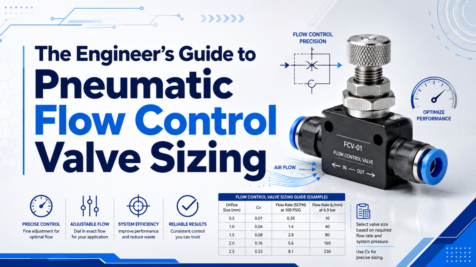
Pneumatic flow control valve sizing is the process of matching an actuator’s required motion to the capacity of its supply and exhaust path. Calculate the air needed to fill or exhaust the cylinder within the target stroke time. Then verify the directional valve, speed controller, tubing, fittings, silencers, and point-of-use pressure as one flow path. That sequence prevents two common errors. Notably, a valve with enough average SCFM may still restrict a fast stroke, while a high-Cv valve cannot overcome a small tube, clogged muffler, or poorly oriented meter-out controller. For the broader definition of the coefficient, see how Cv determines pneumatic valve sizing.
Key Takeaways
- Parker’s published cylinder example requires Cv 1.06 for a one-second stroke.
- Size from required flow during the stroke, not average cycle consumption.
- Treat Cv as one checkpoint in the complete air path.
- Confirm the result with dynamic pressure and timed-stroke measurements.
Stroke Time Comes Before Port Size
Parker’s pneumatic sizing example uses a 3.25-inch bore, 12-inch stroke, 80 psig supply, and one-second stroke time to calculate a required Cv of 1.06 (Parker Hannifin, Pneumatic Valve Products Engineering Data, accessed 2026). The example begins with motion demand, not connection thread.
Port size only tells you how the valve connects.
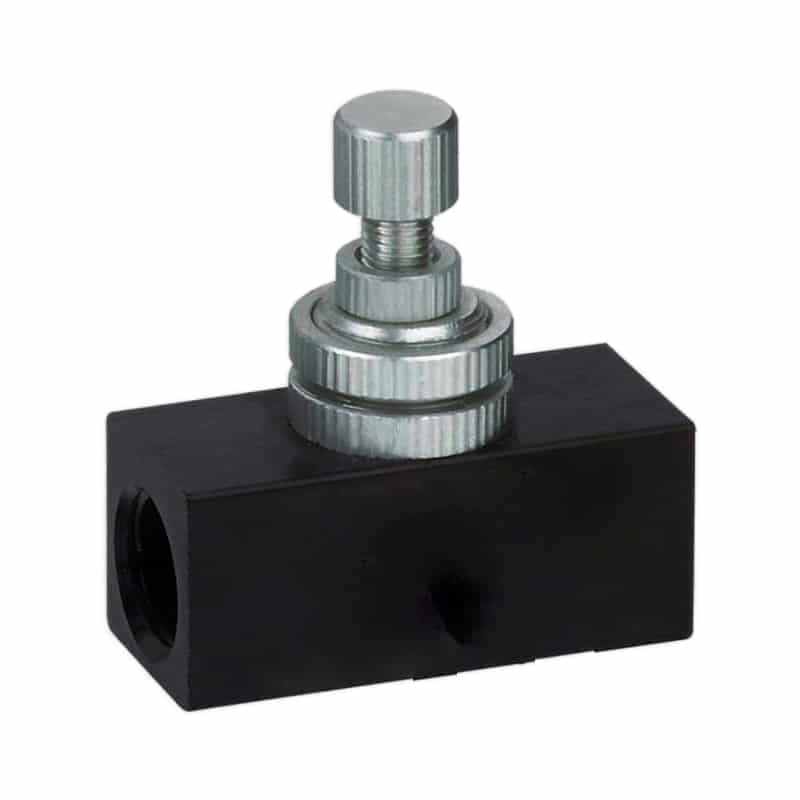
However, it does not reveal the effective internal flow path. Two valves with the same 1/4-inch ports can have different spool passages, seals, exhaust paths, and Cv ratings. In addition, a fitting-style speed controller adds another adjustable restriction, so its free-flow and metered directions matter too.
The practical sizing chain is load and pressure -> cylinder bore -> stroke and target time -> required free-air flow -> valve capacity -> complete-path verification. Starting at the valve skips the actuator demand. Starting at compressor CFM skips the short peak that occurs while the cylinder is actually moving.
What Flow Does the Cylinder Need?
A pressure-ratio calculation must use absolute pressure: NIST defines one standard atmosphere as 14.6959 psi, so 80 psig becomes about 94.7 psia before free-air volume is estimated (NIST, Pressure and Gas Flow Unit Conversions, accessed 2026). Gauge pressure alone understates demand.
For a first-pass extension calculation, use:
piston area = bore² x 0.7854
cylinder volume = piston area x stroke
pressure ratio = (gauge pressure + atmospheric pressure) / atmospheric pressure
free air per stroke = cylinder volume x pressure ratio
required free-air flow = free air per stroke / target stroke time
Keep units consistent.
Specifically, divide cubic inches by 1,728 to obtain cubic feet, or cubic millimetres by 1,000,000 to obtain litres. A single-rod cylinder also needs a separate retract calculation because the rod reduces the annular area and chamber volume.
4-Inch Bore Example
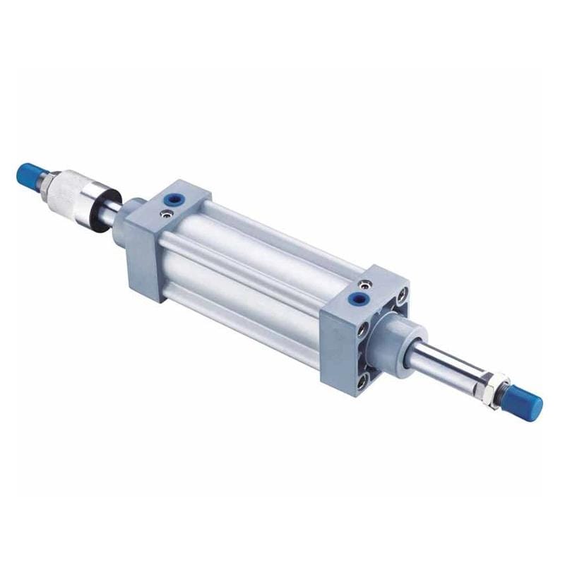
For example, consider a 4-inch bore, 12-inch stroke cylinder at 80 psig. Its cap-end area is 12.57 in² and its geometric chamber volume is about 150.8 in³, or 0.0873 ft³. Using a 14.7 psi atmospheric reference gives a pressure ratio of roughly 6.44 and about 0.562 standard cubic feet per extension before tubing volume and leakage.
If the extension must finish in one second, the local path requires an average equivalent flow of roughly 33.7 SCFM during that one-second interval. Meanwhile, thirty extensions spread evenly over one minute consume about 16.9 SCFM on a cycle-average basis. However, actual instantaneous flow varies as chamber and line pressures change.
Those numbers answer different questions. The first helps size the valve path; the second helps estimate recurring air demand.
Required stroke flow is the average free-air rate needed over the target stroke interval. It should never be substituted with cycle-average consumption. The compressor and receiver support repeated demand over time, while the valve, tube, fittings, and exhaust must handle changing flow during motion. This distinction explains why adequate compressor capacity can coexist with a slow cylinder.
For a complete consumption treatment, use the companion guide to calculating pneumatic flow rate.
How Do You Convert Flow Demand Into Valve Capacity?
Parker calculates Cv with cylinder area, stroke, compression factor, target time, and an A constant tied to allowed pressure drop; at 80 psig the published constants are 0.075, 0.048, and 0.035 for 2, 5, and 10 psi drops (Parker, accessed 2026).
The catalog method is:
required Cv = cylinder area x stroke x compression factor x A
              ------------------------------------------------
                         stroke time x 28.8
Use the manufacturer’s own table or sizing software because the constant depends on inlet pressure and allowed pressure loss. Therefore, do not calculate pneumatic Cv with the liquid shortcut Q / sqrt(ΔP). That expression omits the absolute-pressure and compressibility terms needed for gas flow.
Calculated Cv is a minimum flow-capacity checkpoint.
Accordingly, select the next suitable catalog value, then check both supply and exhaust paths. On a 5/2 valve, the relevant rating can differ by flow direction. Likewise, a speed controller’s free-flow direction needs enough capacity to avoid restricting the opposite stroke.
What About Choked Flow?
Parker’s subcritical equation states that outlet absolute pressure must be greater than 0.53 times inlet absolute pressure. Below the relevant critical pressure ratio, reducing downstream pressure no longer produces the same proportional flow increase. Manufacturer curves or compressible-flow data are safer than extending a low-pressure-drop equation beyond its stated range.
That is where flow-pressure relationship guidance becomes useful. In particular, if the valve catalog provides sonic conductance and critical pressure ratio instead of Cv, use those data rather than converting by guesswork.
How Do Cv, Kv, and ISO 6358 Differ?
The common coefficient conversion is Kv = 0.865 x Cv, while ISO 6358-1 defines steady-state tests for pneumatic components carrying compressible fluids (Swagelok, Valve Selection Guide, accessed 2026; ISO 6358-1:2013, confirmed 2022). These ratings are related, but they are not interchangeable test descriptions or complete sizing methods.
Cv is conventionally based on US gallons per minute of 60°F water at a 1 psi pressure drop. In contrast, Kv uses metric reference units. Both help compare relative valve capacity, but compressed-air prediction still needs upstream absolute pressure, downstream absolute pressure, temperature, and gas properties. ISO 6358 data are built for pneumatic gas components. Depending on the catalog, you may see sonic conductance C, critical pressure ratio b, or newer effective-conductance information. Thus, use one consistent manufacturer method from demand to selection. Don’t combine a liquid Cv equation, an ISO conductance value, and an unrelated catalog SCFM rating in one calculation.
| Catalog value | Best use | Required context |
|---|---|---|
| Cv | Compare valve capacity and use a manufacturer’s pneumatic sizing method | Inlet and outlet absolute pressure, temperature, gas |
| Kv | Compare metric valve catalogs | Convert carefully, then check pneumatic curves |
ISO 6358 C and b |
Calculate compressible pneumatic flow | Test conditions and upstream/downstream pressure |
| SCFM or L/min rating | Quick model comparison | Stated supply pressure, downstream pressure, and standard conditions |
Check the Entire Air Path
CAGI recommends no more than 10% pressure drop from compressor discharge to the point of use in a well-designed system and notes that every 2 psig of excess compressor pressure raises power by about 1% (CAGI, Pressure Drop FAQ, accessed 2026).
The valve body is only one restriction.
In fact, the filter, regulator, manifold, fittings, tube ID, tube length, quick couplers, cylinder ports, cushion needles, exhaust silencers, and speed controllers all consume pressure while air is flowing. Consequently, static regulator pressure cannot show those losses.
Treat the air path as a series circuit. A large valve cannot cancel the pressure drop of a small elbow or saturated filter. Increasing compressor pressure hides the restriction and raises operating cost; measuring pressure immediately upstream and downstream of the moving actuator identifies the limiting section instead.
Use this path checklist after the first Cv selection:
| Check | What to record | Why it matters |
|---|---|---|
| Supply pressure | Pressure at the valve while the cylinder moves | Confirms usable inlet pressure |
| Valve capacity | Cv, ISO 6358 data, or rated flow for each path | Supply and exhaust may differ |
| Tube and fittings | ID, length, elbow count, coupler bore | Reveals distributed restriction |
| Exhaust | Muffler size, manifold passage, meter-out setting | Exhaust restriction controls speed |
| Cylinder | Bore, rod, stroke, cushion setting, load direction | Defines volume and motion demand |
For long lines, compare the result with the guide to causes of pneumatic pressure drop. Additionally, investigate pressure fluctuations during machine operation.
Where Should the Flow Control Valve Be Installed?
Parker identifies two operating arrangements, meter-in and meter-out, and instructs meter-out installations to point the full-flow arrow toward the cylinder port (Parker, Flow Control Valve Service Instructions, accessed 2026). Orientation determines which direction is restricted, how back pressure develops, and how the cylinder responds to an assisting load.
Meter-out is the usual starting point for double-acting cylinder speed control. In this arrangement, supply air passes freely into the filling chamber while the opposite controller meters exhaust. Back pressure on the exhausting side helps resist a load that tends to run ahead, especially on vertical or overhauling motion. Alternatively, meter-in restricts the air entering the cylinder. It can suit stable resisting loads, selected single-acting circuits, or applications where the exhaust should remain free. It is less forgiving when gravity or another external force assists the stroke.
Install fitting-style speed controllers close to the cylinder when practical.
As a result, shorter controlled volumes reduce delay and make adjustment more predictable. Keep the adjustment accessible, confirm the arrow direction, and protect the setting with the valve’s lock mechanism.
For a wider comparison of manual, one-way, directional, and proportional designs, see pneumatic flow control valve types.
What Should You Record During Commissioning?
CAGI recommends changing filter elements when differential pressure reaches 5 to 7 psig, or at least every six months, because filters can become a measurable system restriction (CAGI, Technical Brief on Pressure Drop, accessed 2026). Commissioning data should expose similar losses.
First, record the design inputs before touching the needle adjustment:
- Cylinder bore, rod diameter, stroke, and mounting orientation.
- Moving mass, load direction, and required extension and retraction times.
- Supply pressure at the valve during each stroke.
- Pressure at both cylinder ports during motion.
- Valve model, flow rating, port function, and speed-controller orientation.
- Tube ID and length, fitting count, regulator size, and muffler model.
- Measured extension and retraction time at the production load.
Next, open the speed controller gradually and time several repeat strokes. If speed stops increasing while the controller continues to open, another component has become the limiting restriction. In that case, a temporary pressure gauge at the valve and cylinder port will usually separate supply loss from exhaust loss.
| Symptom | Likely check | Useful test |
|---|---|---|
| Both directions are slow | Supply pressure, regulator, directional valve, common tube | Measure valve inlet during motion |
| One direction is slow | Directional-valve path, one controller, one muffler | Swap or inspect direction-specific components |
| Motion jumps at start | Long trapped volume, meter-in setup, stiction | Move controller closer and verify meter-out direction |
| Speed fades during the shift | Local pressure sag, receiver, shared demand | Log dynamic pressure through the machine cycle |
| Needle has little effect | Oversized controller or another dominant restriction | Compare fully open and partially closed stroke times |
FAQ
Parker’s worked example reaches Cv 1.06 from five operating inputs: cylinder area, stroke, supply-pressure compression factor, allowed pressure drop, and one-second stroke time (Parker, accessed 2026). The answers below keep those variables separate, distinguish local motion demand from cycle-average consumption, and prevent port-size-only selection.
Can I size a pneumatic flow control valve from port size alone?
No. Port size describes the connection, while Cv, ISO 6358 conductance, or a stated pneumatic flow curve describes capacity. Start with cylinder volume and target stroke time. Subsequently, confirm the chosen port, tube ID, fittings, valve path, and exhaust components can pass that demand at the measured pressures.
Does a larger Cv always give better cylinder speed control?
No. A larger Cv raises available capacity, but it can leave too much useful adjustment crowded near the closed end of a manual needle. Instead, select enough capacity for the target stroke, then check controllable adjustment, exhaust stability, and repeatability. A proportional motion requirement may need a different valve architecture.
Should I use cycle-average SCFM or required flow during the stroke?
Use both for different decisions. Specifically, cycle-average SCFM helps estimate compressor, receiver, and recurring air demand. Conversely, required flow during the stroke checks whether the local valve and tube path can fill or exhaust the chamber within the target time. A short, fast stroke can have modest cycle-average consumption but a much higher average rate while moving.
What is the difference between Cv and ISO 6358 conductance?
Cv is a conventional valve-capacity coefficient derived from a water reference and adapted through gas-sizing equations. ISO 6358 defines pneumatic test methods for compressible-fluid components and reports conductance-related characteristics. Therefore, use the rating and calculation method supplied by the same manufacturer instead of mixing coefficients from unrelated test systems.
How can I tell whether the valve or tubing is limiting speed?
Measure dynamic pressure at the valve inlet and near both cylinder ports while timing the stroke. A large upstream drop points toward supply, filtration, regulation, or tubing. On the other hand, adequate valve pressure with slow motion points toward the outlet path, speed controller, muffler, cushion, load, or cylinder friction.
What Is the Final Sizing Rule?
Parker’s Cv 1.06 example and CAGI’s 10% system pressure-drop guidance describe two separate checks: component capacity and delivered pressure (Parker, accessed 2026; CAGI, accessed 2026). A reliable design must pass both; neither check directly substitutes for the other during real machine operation and commissioning.
Calculate the cylinder’s required average free-air flow during the target stroke from bore, rod area, stroke, pressure, and time. Then select a valve using its published pneumatic data. In other words, every restriction between the regulator and exhaust must be verified before commissioning. Install the flow controller in the intended direction and measure pressure during motion.
The timed stroke is the final proof.
Sources and Retrieval Notes
-
Parker Hannifin, Pneumatic Valve Products Engineering Data, pneumatic Cv formula, pressure-drop constants, critical pressure-ratio condition, and worked Cv 1.06 example. Retrieved 2026-07-11.
-
ISO, ISO 6358-1:2013 Pneumatic Fluid Power, steady-state flow testing for compressible-fluid pneumatic components. Retrieved 2026-07-11.
-
NIST, Pressure and Gas Flow Unit Conversions, atmospheric and pressure unit references. Retrieved 2026-07-11.
-
CAGI, Technical Brief on Pressure Drop, pressure-drop sources, filtration checks, and system guidance. Retrieved 2026-07-11.
-
CAGI, Pressure Drop FAQ, 10% system pressure-drop and 2 psig power guidance. Retrieved 2026-07-11.
-
SMC, Pneumatic Flow Rate, Pressure Drop, and Sonic Conductance Software, pneumatic circuit flow and conductance calculation context. Retrieved 2026-07-11.
-
Swagelok, Selecting the Right Valves for Industrial Fluid Systems, Cv definition and gas-flow caveat. Retrieved 2026-07-11.
-
Parker, Flow Control Valve Service Instructions, meter-in and meter-out orientation. Retrieved 2026-07-11.
-
AutomationDirect, How to Select a Pneumatic Cylinder, load, pressure, bore, and stroke selection context. Retrieved 2026-07-11.
-
AutomationDirect, Understanding Pneumatic Valve Ports and Ways, pneumatic supply and exhaust path context. Retrieved 2026-07-11.