

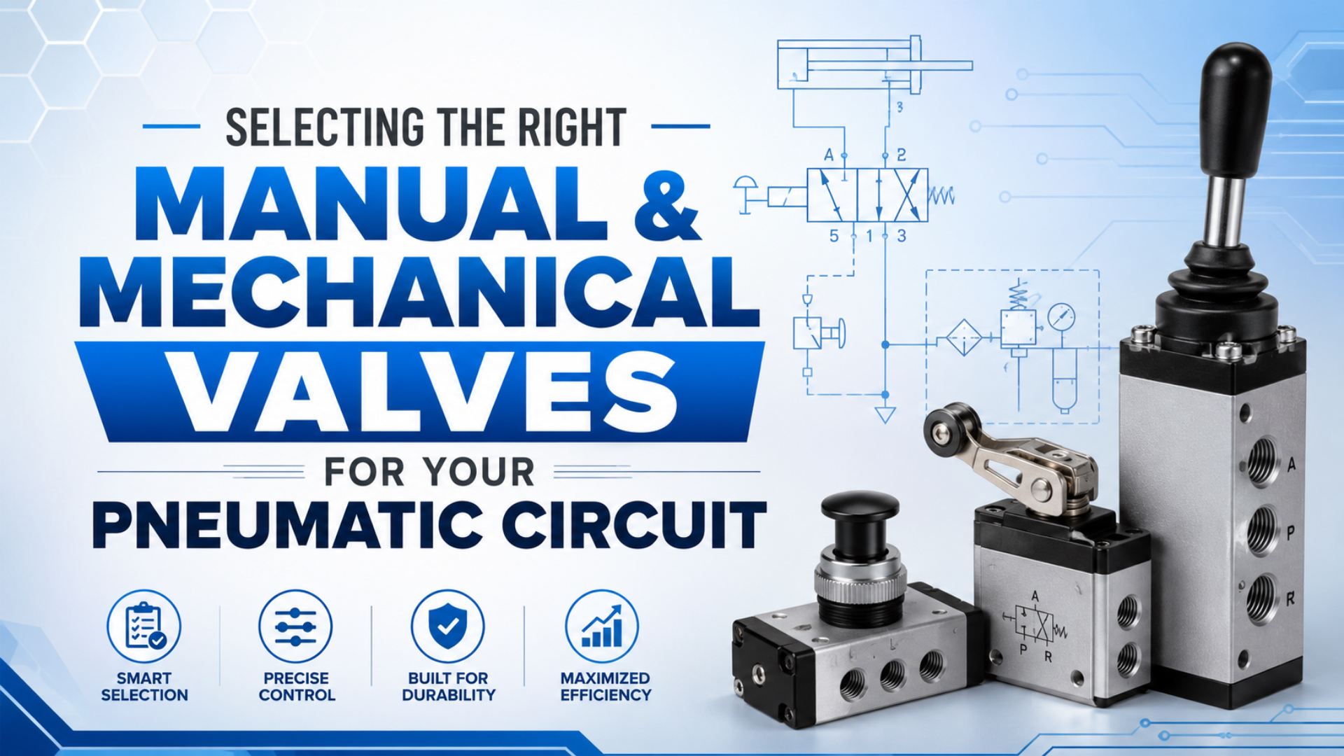
Select manual and mechanical pneumatic valves by defining the circuit function first, then matching the ports, positions, return state, operator, flow capacity, pressure range, environment, and maintenance method. A handle or roller that looks convenient can still be wrong if its normal state, Cv, or exhaust path doesn’t match the machine.
The useful boundary is simple. A manual valve receives deliberate human input through a lever, button, knob, pedal, or treadle. A mechanical valve receives physical input from a cam, roller, plunger, or moving machine element. Check valves and pressure-sequence valves respond to fluid conditions, so they belong in separate selection decisions.
Key Takeaways
- Choose valve function and safe return state before choosing the operator style.
- Current Parker manual and mechanical ranges span 0.17 to 0.83 Cv, so port size alone cannot prove capacity.
- A normal control valve does not replace a lockable energy-isolation device or a verified exhaust procedure.
Manual pneumatic valve is a valve whose position is changed directly by an operator.
Mechanically operated pneumatic valve is a valve shifted by contact with a machine part rather than an electrical signal.
Return state is the valve position after the operating force is removed. It may be spring-return, detented, or locked against unintended shifting.
What Jobs Should Manual and Mechanical Pneumatic Valves Perform?
AutomationDirect’s valve guide assigns a job to each layout: a 2-port, 2-position valve provides on/off isolation, a 3-port valve adds an exhaust path, and a 4-port valve can power a double-acting cylinder in both directions (AutomationDirect, 2026). Start with that job, not the handle shape.
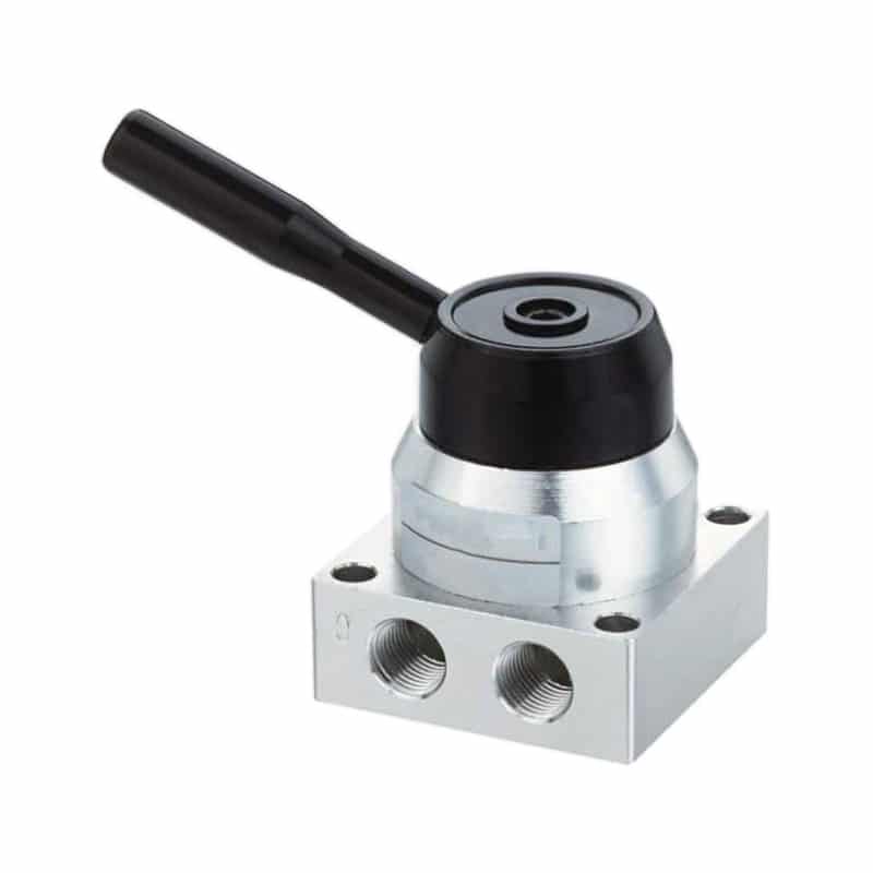
A manual or mechanical operator can be fitted to several valve functions. The operator tells you how the valve shifts; it doesn’t tell you what the internal flow path does. Record the required circuit action in plain language before opening a catalog.
| Circuit job | Typical valve function | Suitable operator | Main selection risk |
|---|---|---|---|
| Isolate a branch | 2/2 on/off | rotary handle or lockable lever | mistaking normal shutoff for energy isolation |
| Send a momentary air signal | 3/2 normally closed | push button, pedal, plunger, roller | wrong return state or insufficient signal flow |
| Vent a single-acting actuator | 3/2 supply and exhaust | button, lever, roller | no clear exhaust route |
| Reverse a double-acting actuator | 4/2 or 5/2 | hand lever, pedal, mechanical roller | wrong port map or inadequate exhaust capacity |
| Select a maintained mode | detented directional valve | lever, knob, selector | unintended restart after air returns |
Don’t treat a check valve as a mechanical limit valve. A pneumatic check valve opens because of differential pressure, while a roller or plunger valve changes state after physical contact. Both may appear in one circuit, but they solve different problems.
The most reliable selection sentence has three parts: input, air-path result, and release behavior. For example, “a guarded foot pedal supplies port A while pressed and exhausts port A when released” is specific enough to expose the correct port count, normal state, and return mechanism.
How Do Ports, Positions, and Return States Change Selection?
Parker’s Directair catalog lists 1/8-inch 3-way and 4-way valves at Cv 0.20, then 1/4-inch versions at Cv 0.83, all in 2-position configurations within the cited range (Parker, 2018). That fourfold capacity difference shows why the symbol and flow data must travel together.
Use ports/positions notation where the supplier provides it. A 3/2 valve has three ports and two positions. A 5/2 valve has five ports and two positions. “Four-way” is sometimes used for a directional function even when the body has five physical ports because the two exhaust ports represent one functional flow direction.
Return behavior matters just as much:
- Spring return: the valve moves to a defined normal position after the force is removed.
- Detent: the valve remains in its selected position until another deliberate input changes it.
- Shift-prevention lock: a separate action is required before the handle can move.
- Momentary mechanical trip: a cam, roller, or plunger shifts the valve only while contact is maintained.
What happens when the operator lets go, the cam passes, or plant air returns after an outage? If the drawing doesn’t answer that question, the valve function is not fully specified. For double-acting cylinders, compare the required behavior with the focused guide to 4-way directional valve control.
Choosing the Operator: Human Input or Machine Contact
SMC’s current VHL hand-valve data lists three operating types and reports up to 58% less footprint, 45% lower weight, and 73% more flow than its comparison model (SMC VHL, 2026). Those figures make the real point: operator geometry, installation space, and flow performance must be reviewed together.
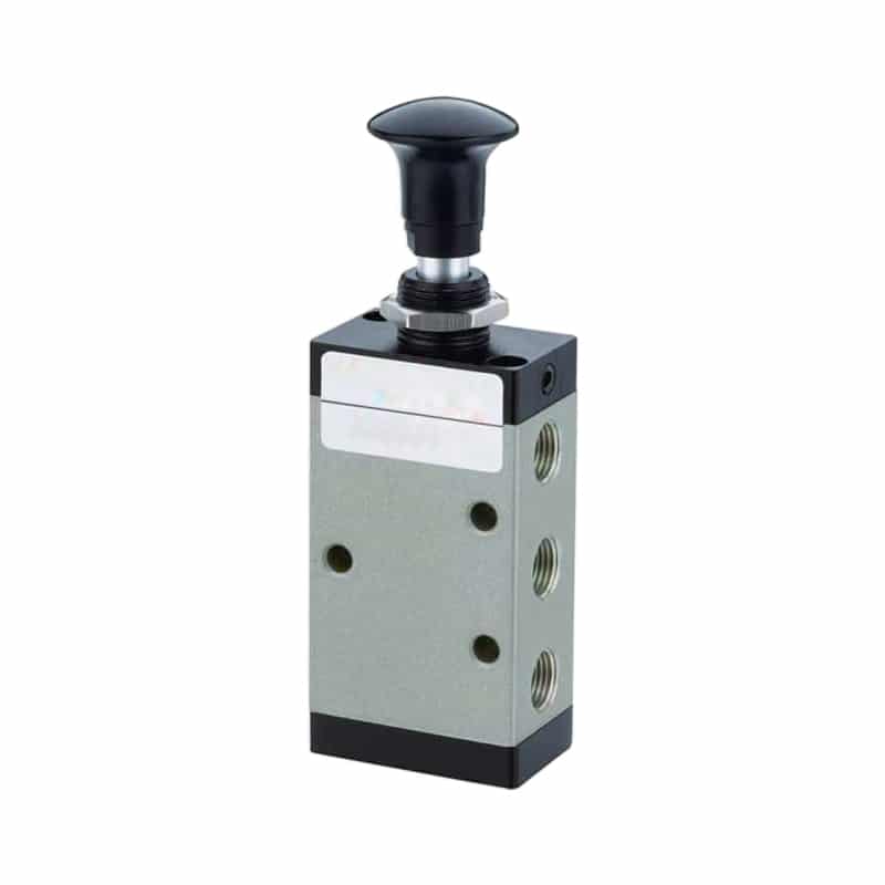
Choose a human-operated interface when a person must intentionally start, stop, jog, isolate, or select a mode. Choose a machine-contact operator when motion itself must create a pneumatic signal. Don’t use a roller valve as a hard travel stop; the actuator mechanism should be contacted within its permitted direction, stroke, and force.
| Operator | Best fit | Questions to resolve before purchase |
|---|---|---|
| Rotary handle or selector | maintained mode or branch control | Is position visible? Is a lock needed? |
| Hand lever | frequent directional control | Spring return or detent? Enough panel clearance? |
| Push button or palm button | momentary signal | Guarded, flush, mushroom, or color-coded? |
| Pedal or treadle | hands-busy operation | Is unintended stepping prevented? Is the floor area clean? |
| Plunger | short, direct machine contact | Is the approach aligned with the rated travel? |
| Roller or roller lever | cam or moving-part detection | Can the cam overtravel without side-loading the stem? |
| One-way tripper | directional pass-by sensing | Is the permitted approach direction documented? |
Ergonomics cannot be reduced to a universal mounting height. Operator reach, posture, gloves, visibility, required force, access during abnormal conditions, and protection from accidental actuation all depend on the machine and task. The RFQ should describe those conditions instead of inventing one “ideal” placement.
How Much Flow Capacity Does the Valve Need?
ISO 6358-1:2013 defines steady-state flow testing and was confirmed in 2022. CAGI separately recommends no more than 10% pressure drop from compressor discharge to point of use in a well-designed system (ISO 6358-1, 2013; CAGI, 2022).
Start with the flow the circuit must pass at the actual upstream and downstream pressures. Then compare Cv, Kv, ISO 6358 conductance data, or a manufacturer flow curve measured under stated conditions. A 1/4-inch connection does not guarantee that every internal spool, seal, elbow, and exhaust passage has the same capacity.
Don’t size every valve at 125% to 150% of calculated flow. A fixed multiplier can hide the real bottleneck or oversize the control. Use the actual simultaneous demand, allowable pressure loss, required response, and exhaust path. If several valves share a manifold, measure dynamic pressure while the circuit cycles, not only idle gauge pressure.
Parker’s current manual and mechanical catalog spans roughly Cv 0.17 to 0.83 in the Directair examples, while SMC lists mechanical models from Cv 0.55 and 0.60 up to Cv 1.0 (Parker, 2018; SMC, 2026). Review valve Cv and system performance when cycle time or pressure loss is the main concern.
Size the smallest signal valve for reliable pilot or logic flow, not actuator flow it never carries. Size a main directional valve for the actuator path it actually carries. Mixing those two jobs is how a compact limit valve gets blamed for a slow cylinder, or a large valve gets installed where only a pneumatic signal was required.
Safe Isolation Is Separate from Normal Control
OSHA 29 CFR 1910.147(d) sets out six application stages before service work: preparation, shutdown, energy isolation, lockout or tagout application, control of stored energy, and verification of isolation (OSHA, 2026). A convenient hand valve is not automatically an energy-isolating device.
OSHA’s rule covers electrical, mechanical, hydraulic, pneumatic, chemical, thermal, and other energy. After isolation, potentially hazardous stored or residual energy must be relieved, disconnected, restrained, or otherwise made safe. If pressure can reaccumulate, verification has to continue until the work is complete or reaccumulation is no longer possible.
ISO 4414:2010 covers pneumatic-system design and safety across construction, installation, operation, maintenance, reliability, energy efficiency, and environmental considerations (ISO 4414, 2010). Apply that system boundary before calling any valve “fail-safe.” The answer depends on the load, actuator, residual pressure, exhaust route, controls, guarding, and restart sequence.
| Normal control question | Maintenance isolation question |
|---|---|
| What motion occurs when the lever is moved? | Can the energy-isolating device be locked in the safe position? |
| Where does actuator air exhaust? | Is stored air relieved or restrained? |
| What is the spring-return state? | Can pressure reaccumulate from another branch? |
| Can the operator see the selected state? | How is zero-energy status verified before work? |
For machinery that needs monitored exhaust and guarding integration, review safety exhaust valve integration. A safety-rated function must be designed and validated as part of the machine safety system; adding a red handle doesn’t create that function by itself.
What Must the Environment and Installation Review Cover?
Parker’s Directair range is rated from vacuum to 150 psi and from 32°F to 175°F, or 0°C to 80°C; those limits apply to that construction, not to all manual valves (Parker, 2018).
Confirm the complete valve part number against the real operating conditions. Temperature affects seals and lubricant. Dust, washdown, chemicals, impact, vibration, outdoor exposure, and panel ingress can affect both the body and operator. A metal lever on a compatible valve body does not prove that the assembled product is suitable for a corrosive or hygienic area.
Check these installation details:
- permitted mounting orientation and panel thickness;
- handle sweep, pedal envelope, roller approach, and overtravel;
- supply, working, and exhaust port identification;
- tubing access without sharp bends or side load;
- visible state marking and durable function labels;
- space to lock, inspect, adjust, and replace the valve;
- downstream motion after pressure is restored.
Could an operator reach the valve during a fault but accidentally strike it during normal work? Could a cam hit the roller from the wrong direction? These questions are more useful than a generic promise of “reliable operation in harsh environments.”
Manual and Mechanical Pneumatic Valve Selection Matrix
SMC lists two 5-port mechanical VZM models at Cv 0.55 and 0.60, while its 5-port VFM range reaches Cv 1.0 (SMC, 2026). Identical port count therefore doesn’t establish equal flow, sealing, pilot arrangement, cycle capability, or operator choice.
| Application | Recommended starting point | Required return behavior | Flow check | Safety boundary |
|---|---|---|---|---|
| Manual branch shutoff | lockable 2/2 valve | maintained closed | branch peak demand and pressure loss | verify whether it qualifies as the isolation device |
| Momentary operator signal | 3/2 normally closed push button | spring return | downstream pilot or logic demand | guard against unintended actuation |
| Hands-busy fixture command | guarded 3/2 or directional pedal valve | usually spring return | actuator or pilot path, depending on circuit | risk-assess foot operation and restart |
| Cylinder end-position signal | 3/2 roller or plunger valve | spring return after cam passes | signal flow and line delay | do not use operator as a physical stop |
| Manual double-acting motion | 4/2, 5/2, or selected 3-position valve | detent or spring return per risk review | supply and both exhaust directions | define pause, air-loss, and restart behavior |
| Maintained mode selection | detented selector or lever valve | stable selected position | control-signal demand | clear indication and protected access |
Treat the matrix as a gate, not a shortcut. If the row can’t be completed without phrases such as “standard flow,” “normal pressure,” or “safe position,” the application data is incomplete. A supplier can quote a part number only after those placeholders become measurable conditions.
What Should Go in the RFQ?
Parker’s Directair examples range from Cv 0.17 to 0.83, nearly a 4.9:1 spread within one manual and mechanical product family (Parker, 2018). An RFQ that says only “1/4-inch manual valve” leaves too much performance undefined.
Send the following data:
- Circuit job and pneumatic symbol, including ports and positions.
- Normal state, spring return, detent, and any shift-prevention requirement.
- Human operator or machine-contact operator, including approach direction and available travel.
- Supply pressure, downstream pressure, required flow, and acceptable pressure drop.
- Medium, temperature range, contamination, washdown, chemicals, and outdoor exposure.
- Port thread, tube size, mounting method, panel thickness, and available envelope.
- Expected operating frequency and whether the valve carries main flow or only a pilot signal.
- Required position indication, labels, lockability, and maintenance access.
- Defined behavior after release, air loss, power loss elsewhere in the machine, and restart.
- Applicable machine-safety and energy-control requirements.
For a multi-valve station, include a circuit diagram and simultaneous-demand case. The guide to building a reliable modular pneumatic circuit explains why shared supply, exhaust, pressure zones, and fault states must be reviewed together. If point-of-use pressure collapses during motion, use the pressure-drop troubleshooting guide before increasing compressor pressure.
FAQs About Selecting Manual & Mechanical Valves for Pneumatic Circuits
Parker and SMC examples cover 2-position 3-way and 4-way functions, up to 150 psi, and Cv 0.17 to 1.0 (Parker, 2018; SMC, 2026). These answers turn those ranges into application checks.
Is a manual shutoff valve the same as a lockout valve?
No. A manual valve may stop normal airflow, but OSHA 1910.147 requires hazardous-energy isolation, control of stored energy, and verification before servicing. Use a device and procedure that meet the site’s energy-control requirements. A convenient handle, color, or closed symbol alone doesn’t prove lockout suitability.
Should I choose spring return or detent?
Choose spring return when removing the operating force must return the valve to a defined normal state. Choose detent when the selected state must remain without continuous force. SMC’s VHL range offers three types: spring return, detent, and detent with shift-prevention lock, so the release behavior must be specified explicitly.
How do I size a manual valve for a cylinder?
Calculate the actuator’s required flow from bore, stroke, pressure, and target time, then check valve Cv or ISO 6358 data with the tubing, fittings, manifold, and exhaust path. Don’t add a universal 125% or 150% margin. Verify dynamic pressure and stroke time under the worst simultaneous operating case.
Can a roller valve stop a cylinder at end of stroke?
A roller valve can create a pneumatic signal when a cam reaches it, but it should not serve as the mechanical travel stop. Confirm the permitted approach, operating travel, overtravel, force, and return direction. The actuator or machine structure needs a separate, appropriate method for managing end-of-travel loads.
What is the difference between 4-way and 5-port valve naming?
AutomationDirect explains that a 5-port valve can still be described as 4-way because its two separate exhaust ports represent one functional exhaust way. Always compare the pneumatic symbol and port labels. For a double-acting actuator, identify supply, both working ports, both exhaust paths, and every spool position.
Source Notes and Retrieval Dates
- AutomationDirect, Understanding Pneumatic Valve Ports & Ways, port, position, and way definitions. Retrieved 2026-07-11.
- ISO 4414:2010, pneumatic-system safety scope. Retrieved 2026-07-11.
- ISO 6358-1:2013, steady-state flow-characteristic test method. Retrieved 2026-07-11.
- OSHA 29 CFR 1910.147, hazardous-energy control, stored energy, and verification. Retrieved 2026-07-11.
- Parker Pneumatic Manual Valves Catalog, Directair operator, function, pressure, and Cv examples. Retrieved 2026-07-11.
- Parker Manual / Mechanical Products Catalog 0600P-13, operating range, materials, functions, and flow data. Retrieved 2026-07-11.
- SMC Mechanical & Hand Operated Valves, VHL, VZM, VFM, and related product data. Retrieved 2026-07-11.
- CAGI Technical Brief on Pressure Drop, compressed-air pressure-drop guidance. Retrieved 2026-07-11.