

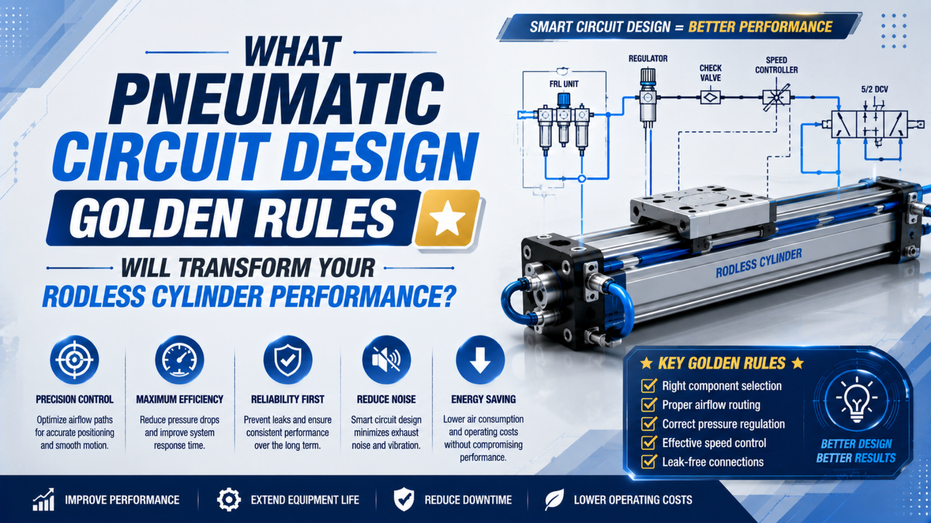
Rodless cylinder pneumatic circuit design is the process of treating the actuator as one flow path, one motion system, and one defined set of machine states. The cylinder cannot compensate for an undersized regulator, a distant valve, restrictive tubing, uncontrolled exhaust back pressure, an unsafe restart, or a coupling that allows the wrong line to be connected.
Seven rules keep those interfaces visible. Define the safe state first. Size the entire inlet and exhaust path for peak flow. Control speed in both directions. Specify air preparation from product requirements. Prevent wrong connections physically. Then prove the installed circuit with synchronized position and pressure measurements.
Key Takeaways
- ISO 6150 defines three quick-coupling pressure classes, but dimensional fit does not prove functional compatibility.
- Cylinder speed depends on flow, effective area, tubing, ports, load, and exhaust restriction.
- Treat FRL units, valves, controls, silencers, and couplings as one pressure budget.
- Commission with measured traces, not regulator settings alone.
Rule 1: What Must the Circuit Do in Every Machine State?
A circuit must define its behaviour before component sizing begins. ISO 4414:2010 addresses pneumatic-system design, installation, adjustment, operation, maintenance, energy efficiency, and significant machinery hazards, so a normal run command is only one of several states that require an explicit outcome (ISO, confirmed 2021).
Start with a state table. It should describe the valve command, actuator movement, stored pressure, load condition, and restart permission for each foreseeable state.
| Machine state | Required circuit decision |
|---|---|
| Normal production | Which direction is commanded, how speed is controlled, and how end position is confirmed |
| Controlled stop | Whether the carriage stops immediately, completes the stroke, or moves to a defined position |
| Emergency stop | Which safety function removes or blocks motive energy and what prevents hazardous movement |
| Air isolation | How upstream air is locked out and downstream residual pressure is relieved or restrained |
| Pressure restoration | Whether soft start is required and what prevents an automatic unexpected stroke |
| Sensor or valve fault | Which state is entered when position feedback or valve response is missing |
A soft-start valve limits the rate of pressure restoration. It is not automatically a safety-rated stopping or load-holding device. Likewise, a closed-centre directional valve may trap pressure without guaranteeing that leakage, hose failure, or mechanical load cannot move the carriage.
Vertical, inclined, and externally loaded axes need special attention. Exhausting both chambers can release a suspended load. Trapping both chambers can leave stored energy on both sides of the piston. The risk assessment must decide whether a rod lock, mechanical brake, counterbalance arrangement, guarded stop, or another engineered measure is required.
OSHA’s lockout rule includes pneumatic energy and requires stored or residual energy to be relieved, disconnected, restrained, or otherwise rendered safe before covered servicing work (OSHA 1910.147). Put the isolation point, dump path, gauge, and verification method on the circuit drawing.
The first golden rule is therefore not “choose a 5/2 valve.” It is “write the state table.” Once every state has a required physical outcome, valve type, centre condition, pilot arrangement, exhaust strategy, sensing, and restart logic can be selected against that outcome.
Rule 2: How Much Peak Flow Must Reach the Cylinder?
Peak flow follows the required directional speed and effective area. SMC gives the relationship for speed in inches per second, flow in SCFM, and area in square inches, while warning that inlet pressure must remain constant and that tubing and port sizes still affect speed (SMC, accessed 2026).
In unit-independent form, the working-volume relationship is:
is volumetric flow at the cylinder chamber’s working pressure and temperature, is the effective piston area for the selected direction, and is target piston velocity. Use compatible units, such as cubic metres per second, square metres, and metres per second.
Catalog flow is usually stated at a standard or normal reference condition. A preliminary ideal-gas conversion is:
is reference-condition flow, is approximate absolute chamber pressure, is reference absolute pressure, and and are absolute temperatures. State the chosen reference because NL/min, SLPM, and SCFM may use different conventions.
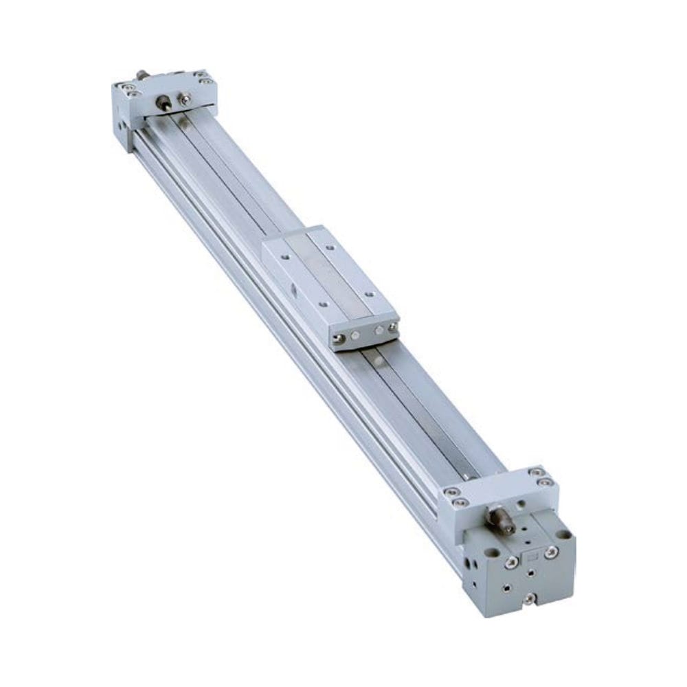
Do the calculation separately for extension and retraction. A single-rod cylinder has different effective areas in the two directions. A mechanically jointed or magnetically coupled rodless cylinder may use equal or nearly equal pressure areas, but the exact product data still governs.
Average consumption is not peak flow. If several actuators overlap for 150 ms, the FRL, manifold, valve, tubing, and exhaust path must pass the simultaneous demand during that interval. Summing full-cycle averages can hide the short pressure collapse that slows a critical move.
ISO 6358-1 standardizes steady-state flow testing for pneumatic components using compressible fluids. Use the valve, regulator, coupling, and silencer data at the applicable pressure ratio rather than comparing port threads alone (ISO 6358-1, confirmed 2022).
The FRL sizing guide explains how to read regulator flow curves and droop data. Use the Compressed Air Pressure Drop Calculator for a defined pipe or tube segment, but confirm short machine tubing and fittings with exact product data or measurement.
Rule 3: Where Should the Valve and Tubing Be Placed?
Valve location and tubing geometry change the delivered motion. SMC identifies both port size and tubing size as speed factors beyond the commanded flow, which means two circuits with the same regulator setting and valve part number can behave differently when tube length, inside diameter, fittings, or exhaust routing changes (SMC).
Place the directional valve close enough to the rodless cylinder that tube volume does not dominate response time, while preserving access, environmental protection, and safe maintenance. There is no universal maximum tube length. The acceptable value depends on bore, stroke, target time, valve conductance, tube inside diameter, pressure, and permissible delay.
Use the same disciplined approach in both directions:
- Record actual tube inside diameter, not nominal outside diameter.
- Count elbows, reducers, bulkhead fittings, manifolds, couplings, and flow controls.
- Avoid unnecessary differences between the two work-port paths.
- Support tubing so carriage motion cannot rub, kink, pull, or fatigue it.
- Keep exhaust paths identifiable and serviceable.
- Put pressure test points near the valve inlet and both cylinder ports.
Long moving axes also need mechanically safe tubing routing. The pneumatic tubing routing guide covers bend radius, support, abrasion, heat, movement, and service loops.
Rule 4: Why Should Speed Usually Be Controlled at the Exhaust?
Meter-out control is the common starting point for cylinder speed regulation. SMC states that industry practice usually controls flow at the actuator exhaust port, where changing back pressure changes piston speed; this is commonly implemented with a meter-out flow control or needle valve (SMC).
Meter-out control maintains pressure on the driving side while restricting the exhausting side. That generally gives better control of loads that might otherwise run ahead of the supplied air. Fit and adjust controls for both directions because the carriage load, gravity component, effective area, cushion behaviour, and required time may differ.
“Usually” matters. The correct circuit still depends on the actuator and load:
- An overrunning or vertical load needs a defined restraint strategy, not just a needle valve.
- Very low-speed motion may expose stick-slip that a conventional flow control cannot eliminate.
- A magnetically coupled rodless cylinder must remain within its coupling-force limit.
- A mechanically jointed rodless cylinder must stay within guide, moment, and speed ratings.
- A proportional or servo-pneumatic axis needs a different valve and feedback architecture.
Adjust speed before tuning end cushioning. Measure both directions with the production load. A nearly closed exhaust control can create high back pressure, heat, and slow cushion response. A fully open path may allow excessive cushion-entry speed and hard end impact.
Do not add a quick-exhaust valve solely because the cylinder is slow. It changes where the chamber vents, how the cushion sees exhaust pressure, and whether the normal valve can stop or reverse the load as intended. The quick-exhaust valve physics guide covers those tradeoffs.
Rule 5: Treat the Exhaust Path as a Performance Component
Nominal thread size does not establish silencer capacity. Festo’s 2024 catalog lists G1/8 variants from 1,340 to 2,050 L/min at a stated 6 bar inlet condition. That spread shows why tested flow data, not the thread alone, must drive selection (Festo).
OSHA uses 85 dBA as an eight-hour TWA hearing-conservation action level rather than a single-machine emission limit (OSHA).
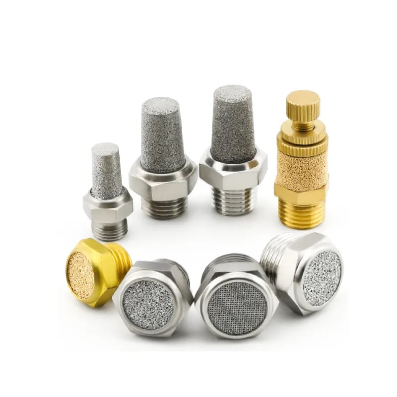
The exhaust path includes the cylinder port, work-port tubing, meter-out control, directional valve gallery, manifold exhaust, remote exhaust tubing, silencer, and any exhaust cleaner. A restriction anywhere in that chain can raise the pressure opposing piston motion.
Back pressure reduces the available pressure difference across the piston. It can slow one direction while the other remains normal, which is why “the supply gauge still reads 6 bar” does not clear the exhaust path.
Select and commission the exhaust system by checking:
- Manufacturer flow data at the relevant pressure condition.
- Separate exhaust demand for extension and retraction.
- Clean-state pressure and stroke-time baselines.
- Oil mist, water, dust, icing, corrosion, and cleaning permission.
- Exhaust temperature and material compatibility.
- Noise at the operator position and total exposure duration.
- Access for inspection and replacement.
Remote mounting may improve access or move the acoustic source, but extra tube and fittings can increase restriction and volume. No universal distance expressed as a multiple of port diameter can replace a pressure and timing test.
ISO 20145:2026 specifies acoustic test methods for pneumatic exhaust silencers. The product’s stated test result and the workplace exposure measurement answer different questions: one compares a component under defined conditions; the other evaluates people at the installed machine (ISO, 2026).
The strongest maintenance baseline is a paired trace: cylinder-port pressure and stroke time for the same loaded cycle. If exhaust pressure rises while the affected direction slows, investigate the flow control, valve gallery, tubing, and silencer as one path. The silencer-clogging guide provides the detailed A/B test.
Rule 6: How Should Air Preparation Be Specified?
Air preparation starts with purity and dynamic flow requirements. ISO 8573-1 classifies compressed-air purity by particles, water, and oil. Specify those three groups at the point of use, then add minimum dynamic pressure, peak flow, and allowable pressure drop before choosing a filter-regulator (ISO).
Festo’s current portfolio spans 0.01 to 40 micrometre filtration grades and 140 to 24,000 L/min filter-regulator flows, illustrating why one generic “industrial air” specification is insufficient (Festo, accessed 2026).
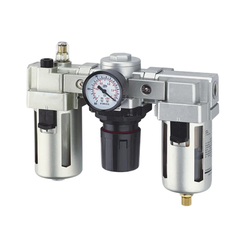
Do not choose an FRL from port size or an application label such as “standard industrial.” Collect:
- Minimum and maximum inlet pressure during production.
- Required outlet pressure at peak flow.
- Allowable regulator droop and hysteresis.
- Peak simultaneous flow and flow-reference condition.
- Required particle, water, and oil class at the point of use.
- Ambient and compressed-air temperature range.
- Condensate load and drain type.
- Bowl material and chemical exposure.
- Service access and differential-pressure monitoring.
ISO 6953-2:2024 standardizes regulator and filter-regulator characteristic tests and data presentation. Use the exact model’s forward-flow curve at the planned inlet pressure and setting. A headline free-flow value does not prove that the regulator will hold the required outlet pressure during a rapid cylinder event (ISO, 2024).
A lubricator is not automatically required. Many modern pneumatic components are designed for non-lubricated operation. If the exact manufacturer requires added oil, specify the oil type and delivery method, and recognize that downstream components may then depend on continued lubrication. Do not add a lubricator as a generic reliability upgrade.
Measure regulator inlet and outlet pressure during the same peak event. Stable inlet pressure with excessive outlet droop directs attention to the filter-regulator or its element. If both pressures collapse, investigate the upstream supply, distribution pipe, isolation valve, or concurrent demand.
Rule 7: How Should Couplings and Connections Be Mistake-Proofed?
Physical compatibility must be separated from functional compatibility. ISO 6150:2018 defines cylindrical quick-action coupling plugs in three maximum-working-pressure classes, 10, 16, and 25 bar, but leaves socket construction to the manufacturer and does not guarantee every functional characteristic (ISO, confirmed 2025).
A push-in tube fitting is not a quick-action coupling. ISO 14743 covers complete push-in connectors for thermoplastic tube from 3 through 16 mm outside diameter. Those fittings normally form a fixed circuit connection; plug-and-socket couplings are designed for repeated connection and disconnection (ISO, 2021).
Use a layered mistake-proofing strategy:
- Physical prevention: Use different coupling profiles, body sizes, dedicated manifolds, or locations when cross-connection could create a hazard.
- Permanent identification: Mark both connection halves, tubing, schematic, and machine port with the same circuit identifier.
- Functional verification: Confirm pressure class, flow, retention, shutoff, venting, seal material, temperature, and media compatibility.
- Safe disconnection: Isolate and vent according to the product and workplace procedure; control hose-whip and stored-energy hazards.
- Post-maintenance test: Verify valve state, motion direction, pressure traces, leakage, and sensor sequence before returning the machine to production.
Colour is useful, but it should reinforce rather than replace physical prevention and identification. Labels can fade, tubing can be replaced, and colour conventions differ between plants.
Quick couplings also consume pressure budget. A mechanically correct connection may still be too restrictive for a high-speed rodless cylinder. Compare its flow data at the actual pressure condition and verify dynamic cylinder-port pressure after installation.
The quick-action coupling guide explains ISO profiles, shutoff and venting options, flow checks, and maintenance in more detail.
Commissioning Checklist for a Rodless Cylinder Circuit
Commissioning must reproduce the real operating envelope. ISO 6953-2:2024 provides standardized regulator comparison tests, but it does not certify the installed machine; the completed circuit still needs simultaneous measurements at minimum and maximum load, both travel directions, and the lowest expected dynamic inlet pressure (ISO, 2024).
Record every signal against one time base:
- Valve command.
- Valve or spool feedback when available.
- Pressure before the air-preparation assembly.
- Regulated pressure at the valve inlet.
- Pressure at both cylinder ports.
- Carriage position.
- End-sensor transitions.
- Cycle identifier, payload, orientation, and temperature.
Run at least these cases:
| Test case | What to verify |
|---|---|
| Minimum and maximum payload | Stable motion, coupling or guide margin, cushioning, and end-position repeatability |
| Extension and retraction | Direction-specific pressure, stroke time, speed control, and exhaust behaviour |
| Lowest expected inlet pressure | Adequate dynamic pressure at the cylinder ports |
| Cold start and warm production | Seal friction, regulator behaviour, condensation, and timing drift |
| One actuator and peak overlap | Local performance and simultaneous-demand pressure loss |
| Controlled stop and pressure restoration | Defined safe state, no unexpected restart, and correct sensor sequence |
Define acceptance limits before testing. Useful limits include stroke time, command-to-motion delay, minimum cylinder-port pressure, maximum exhaust pressure, cushion-entry speed, settling time, position repeatability, leakage, and sound exposure. Use the exact actuator, valve, FRL, silencer, and coupling limits as boundaries.
For technical review, send the circuit schematic, component part numbers, bore, stroke, load, orientation, tube dimensions, required timing, and synchronized traces through the technical contact page. Those inputs reveal far more than a photo of the regulator gauge.
Rodless Cylinder Circuit Design FAQs
Circuit decisions cross several standards and product boundaries. ISO 8573-1 uses three primary compressed-air contaminant groups, while ISO 6150 defines three quick-coupling pressure classes. Neither standard selects a complete rodless-cylinder circuit, so these answers connect purity, flow, exhaust, connection, and commissioning requirements without turning one number into a universal rule.
Should the FRL match the rodless cylinder’s port size?
No. Port thread is an interface, not a flow guarantee. Select the FRL from peak simultaneous flow, minimum dynamic inlet pressure, required outlet pressure, allowable droop, air-purity requirement, and the exact model’s flow curve. Then measure FRL inlet and outlet pressure during the fastest loaded cylinder event.
Is meter-out control always correct for a rodless cylinder?
Meter-out is the normal starting point because exhaust restriction creates controllable back pressure, but it is not universal. Check load direction, gravity, coupling limits, minimum speed, cushion behaviour, valve architecture, and the required safe state. A vertical or overrunning load may need a separate engineered restraint rather than a needle valve alone.
Can a pneumatic silencer be mounted remotely?
Yes, if the manufacturer allows the arrangement and the added tube, fittings, temperature, drainage, contamination, and back pressure remain acceptable. Remote mounting can improve access or move noise, but it can also add restriction and volume. Verify both cylinder-port pressure and stroke time with the final installed exhaust path.
Does every rodless cylinder circuit need a lubricator?
No. Follow the exact cylinder, valve, flow-control, and accessory specifications. Many modern components are intended for non-lubricated operation. If added lubrication is required, specify the compatible oil and delivery rate, and recognize that downstream components may depend on continued lubrication once oil has been introduced.
What proves that a rodless cylinder circuit is commissioned?
A regulator setting does not prove commissioning. Record valve command, dynamic FRL inlet and outlet pressure, both cylinder-port pressures, carriage position, sensor timing, payload, orientation, and temperature on one time base. Pass written limits in both directions at minimum and maximum load, low inlet pressure, cold start, and peak simultaneous demand.
Sources and technical references
- ISO 4414:2010, pneumatic-system safety requirements
- ISO 6358-1:2013, flow-rate characteristics of pneumatic components
- ISO 6953-2:2024, regulator and filter-regulator test methods
- ISO 8573-1:2010, compressed-air purity classes
- ISO 6150:2018, cylindrical quick-action couplings
- ISO 14743:2021, push-in connectors for thermoplastic tubes
- ISO 20145:2026, acoustic test methods for exhaust silencers
- SMC, Control Air Flow of Cylinders
- Festo, Silencer U technical data
- OSHA, Occupational Noise Exposure
- OSHA 1910.147, Control of Hazardous Energy