

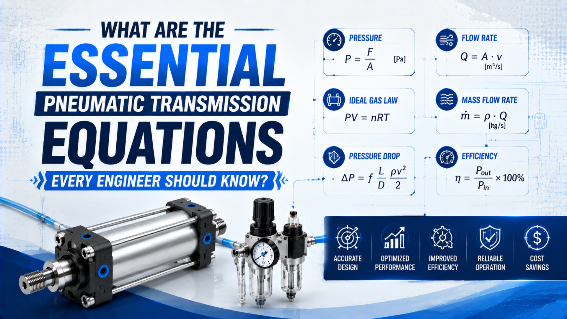
The essential pneumatic transmission equations form a calculation chain: convert gauge values to absolute states, calculate cylinder geometry, determine net force, convert chamber volume to a stated air-flow reference, and then verify speed, valve capacity, and pressure drop. Memorizing , , and without those boundaries can produce a plausible but unusable answer.
NIST lists one standard atmosphere as 101,325 Pa and warns that “standard” gas-flow units can use different reference temperatures. ISO 6358 treats pneumatic component flow as compressible and distinguishes subsonic from choked behavior. Those two facts set the ground rules: write the pressure basis, temperature basis, flow reference state, and system boundary beside every result.
Key Takeaways
- Use absolute pressure and kelvin for gas-state calculations.
- Use pressure differential, effective area, and friction for cylinder force.
- Keep standard flow separate from chamber flow and line velocity.
- Average air use does not prove that a valve can deliver peak flow.
Start With Units and Reference States
NIST defines 1 atm as 101,325 Pa and 1 psi as 6,894.757 Pa, while its gas-flow guidance notes that standard cubic centimetres can use different reference temperatures (NIST, updated 2025). Write the reference pressure and temperature whenever a calculation converts compressed volume into free-air volume.
Four labels prevent most unit and state errors:
- Gauge pressure is measured relative to the local atmosphere.
- Absolute pressure is measured from a perfect vacuum.
- Actual volumetric flow belongs to the pressure and temperature at the stated section.
- Referenced volumetric flow has been converted to a declared pressure and temperature, such as SCFM, SLPM, NL/min, or ANR.
Convert pressure and temperature before applying a gas law:
is absolute pressure, is gauge pressure, and is the atmospheric pressure used for the calculation. is absolute temperature in kelvin and is temperature in degrees Celsius. At altitude, use the relevant measured or specified atmospheric pressure rather than automatically adding 101.325 kPa.
Force calculations are different. When both sides of a piston ultimately reference the same atmosphere, gauge pressures can be used consistently in the two pressure-area terms. Don’t add atmospheric pressure to one chamber and omit it from the other.
A pneumatic result is not fully defined until its state tag is attached. “120 L/min” can describe compressor free air, valve catalog flow, actual tube flow, or chamber flow. Those quantities may represent the same mass rate at different densities, but they don’t have the same volume rate or velocity.
How Does the Ideal Gas Law Apply to Pneumatic Systems?
NIST describes thermodynamic temperature as the absolute temperature appearing in the ideal-gas relation (NIST, 2021). In industrial pneumatics, the ideal gas law is most useful for converting the same quantity of air between pressure, volume, and temperature states, not for predicting a regulator’s behavior by itself.
The molar form is:
is absolute pressure, is volume, is amount of gas in moles, is the molar gas constant, and is absolute temperature. For the same trapped quantity of air at two equilibrium states, cancels:
This relationship is useful for a receiver, isolated chamber, pressure-decay test, or reference-state conversion. It does not say that a working cylinder’s pressure must rise in direct proportion to ambient temperature. A connected pneumatic circuit can exchange mass through its regulator, valves, seals, and exhaust while piston motion changes volume.
Use a control-volume diagram before choosing a gas equation. Is the gas mass trapped? Is the volume fixed? Has the temperature settled? A fast cylinder fill is not perfectly isothermal, and a regulator creates mass flow rather than preserving one closed quantity of air.
For a dedicated treatment of gauge, absolute, and atmospheric pressure, see What Is Absolute Pressure and How Does It Impact Pneumatic System Performance?.
Which Cylinder Areas and Volumes Belong in the Calculation?
ISO 15552 covers standard detachable-mounting cylinders with 32 mm to 320 mm bores and a maximum rated pressure of 1,000 kPa, or 10 bar (ISO 15552, 2018). Those catalog dimensions define the piston and rod geometry; outside barrel diameter and total external surface area do not calculate thrust.
For bore diameter and rod diameter :
is full piston area. is the rod-side annular area of a single-rod cylinder. The corresponding swept chamber volumes for stroke are:
is cap-end swept volume and is rod-end swept volume. Add port, cushion, valve, manifold, and tube dead volumes when they are filled and exhausted with the chamber. Long tubing can materially change air use and response even though it produces no piston force.
A rodless cylinder may have equal or nearly equal pressure-acting areas in both directions, but the exact product drawing controls. Sealing bands, internal rods, magnetic structures, cushion assemblies, or different port volumes can change what belongs in the force and air-use model.
The existing cylinder formula reference develops the geometry and bore-selection calculations in more detail. This article keeps the geometry brief so it can connect that result to the wider transmission system.
What Is the Correct Pneumatic Cylinder Force Equation?
Parker defines theoretical cylinder force from pressure acting on piston area, but real output must account for the pressure on the opposing side and mechanical resistance (Parker Engineering Data, accessed 2026). Use pressures measured at both cylinder ports during the specified motion when calculating available force.
For extension of a double-acting single-rod cylinder:
is cap-end gauge pressure, is rod-end gauge pressure, and is measured or model-specific resistance opposing extension. Because both pressures use the same atmospheric reference, they can be combined consistently. For retraction, exchange the active pressure-area terms and use the resistance for that direction.
Don’t hide every uncertainty inside one efficiency factor. Compare available force with a separately calculated requirement:
is the process load, is the component of weight along the motion axis, is moving mass, and is required acceleration. Apply a documented design margin after these physical terms are identified.
Mechanical output power during steady motion is:
is mechanical power in watts when force is in newtons and cylinder velocity is in metres per second. It is not compressor electrical input. A pneumatic system’s overall efficiency requires compressor, distribution, valve, exhaust, leakage, and duty-cycle data.
The cylinder force-loss guide provides the complete two-chamber calculation and measurement sequence.
How Do You Convert Chamber Volume Into Air Consumption?
Parker’s pneumatic-cylinder guide converts displaced chamber volume to free-air consumption with an absolute-pressure ratio, adding 14.7 psi to gauge pressure before dividing by atmospheric pressure (Parker Application Engineering Guide, accessed 2026). A temperature term is also needed when the operating and reporting temperatures differ.
For chamber volume at operating absolute pressure and temperature , the equivalent volume at declared reference conditions is:
is referenced air volume for the same mass of ideal gas. State and beside the result. The letter is only a label here; it does not establish a universal definition of “normal” conditions.
For a double-acting cycle, calculate the supplied air for each powered chamber and add them:
Average referenced flow at cycle rate is:
Average consumption sizes compressor loading and long-term energy use. A valve must also deliver each chamber’s air during its actual stroke time. For an extension lasting :
This is a first-pass mean flow during the event, not the instantaneous compressible-flow curve. Include pressure ramp, cushion volume, tube volume, leakage, valve switching, and motion profile when the cycle is demanding. Estimate the event flow with the Cylinder Flow Requirement Calculator, then verify the selected components against their catalog method.
Why Does Q = vA Need a Density Check?
NASA states that mass flow through a tube is and remains constant in steady flow, while density changes when gas compressibility matters (NASA, accessed 2026). The shorter relation is valid only for actual volumetric flow at the same local density and section.
Use separate symbols for piston velocity and air velocity:
is average piston or carriage speed over stroke and time . is the geometric chamber fill rate at chamber conditions for effective piston area . It is not automatically SCFM or SLPM.
For air moving through a tube:
is mass flow, is local air density, is local mean air velocity, and is flow-passage area. If the same mass rate moves from a high-pressure chamber to a low-pressure exhaust, density changes, so actual volume rate and velocity can change along the path.
In our experience, the most common spreadsheet error is dividing a valve’s standard litres per minute directly by piston area and calling the result cylinder speed. Convert the catalog flow to the required state or use the manufacturer’s sizing method first. Then check the actual stroke time on the machine.
When Must Valve Flow Use ISO 6358 or Cv Data?
ISO 6358-1 specifies steady-state testing for pneumatic components using compressible fluids, and the 2026 standard includes an amendment covering measurement uncertainty (ISO 6358-1, 2013 with 2026 amendment). Use the component’s stated sonic conductance and critical pressure ratio, or an approved Cv method, instead of treating a valve as a plain tube.
At a large enough upstream-to-downstream pressure ratio, the narrowest part of a flow path can choke. Lowering downstream pressure further then does not create the proportional increase predicted by an incompressible equation. NASA describes the limiting condition as Mach 1 at the controlling throat (NASA, accessed 2026).
ISO 6358-3 provides a method for calculating the combined steady-state flow characteristics of pneumatic components and piping with known characteristics, covering both subsonic and choked flow (ISO 6358-3, 2014).
For each supply and exhaust path, collect:
- upstream absolute pressure and temperature;
- required downstream pressure or allowed pressure drop;
- required referenced flow during the stroke;
- valve sonic conductance and critical pressure ratio, or its documented Cv basis;
- regulator, FRL, fitting, tube, manifold, speed-control, and silencer data;
- flow direction, because supply and exhaust capacities may differ.
Port thread size does not prove internal capacity. Two valves with the same thread can have different orifices, spool geometries, and tested flow characteristics. The air-flow to pressure guide develops the ISO 6358 and choked-flow decision separately.
How Should Engineers Estimate Pressure Drop?
The US Department of Energy’s compressed-air sourcebook recommends measuring system pressure profiles and notes that pressure drop is caused by friction and restrictions throughout piping and components (DOE Sourcebook, accessed 2026). A fixed 0.1 bar allowance or one universal tube velocity limit cannot represent every machine cycle.
For a defined steady pipe segment, the Darcy-Weisbach form plus minor-loss coefficients is a useful screening equation:
is pressure loss, is Darcy friction factor, is pipe length, is inside diameter, represents fittings and local restrictions, is the density used for the segment, and is mean velocity at that state.
For compressed air, density can change along the run. Long lines, large pressure ratios, high flow, and restrictions near choking need a compressible method, measured component data, or segmented calculation. A Darcy estimate also does not replace valve, regulator, filter, or silencer flow curves.
Measure static and dynamic pressure at:
- machine inlet;
- upstream and downstream of the FRL;
- valve manifold inlet;
- both cylinder ports during the relevant stroke;
- the exhausting chamber when back pressure is suspected.
Use the Compressed Air Pressure Drop Calculator for a first-pass straight-run estimate. Then compare the calculated loss with time-aligned pressure measurements. The measurement tells you whether the assumed flow, roughness, density, and restriction model describes the actual machine.
A pressure-drop calculation should end with a measurement location, not only a pipe diameter. If the design requirement is force at the workpiece, the decisive value is dynamic pressure at the cylinder port. If the requirement is stroke time, both supply and exhaust pressure histories matter.
Worked Example: Force, Air Use, and Peak Flow
This example uses 101.325 kPa as atmospheric reference because NIST defines that value as 1 atm (NIST, updated 2025). It assumes a 50 mm bore, 20 mm rod, 300 mm stroke, 20 degrees Celsius in both operating and reference states, and an illustrative 20 cycles per minute.
During extension, measured cap-end pressure is 0.55 MPa gauge and rod-end pressure is 0.08 MPa gauge. Measured running resistance is 80 N. The extension must finish in 0.60 seconds.
First calculate piston and annular areas:
Because 1 MPa equals 1 N/mm², available extension force is:
The result is not a rated payload. The engineer must still subtract or compare gravity, acceleration, process force, fixtures, uncertainty, and the required design margin.
Cap-end swept volume is:
Supply absolute pressure is 651.325 kPa. With equal operating and reference temperatures, the extension air expressed at 101.325 kPa is:
Assuming retraction uses the same 0.55 MPa gauge supply pressure, its corresponding volume is 3.181 L at the same reference state. One full cycle therefore uses 6.967 reference litres before tube dead volume and leakage.
At 20 cycles per minute:
The extension event asks for a much higher mean flow during its 0.60 second window:
This difference explains why a compressor can cover average consumption while an undersized local valve or tube still misses the stroke-time target.
Which Equations Belong on an Engineering Worksheet?
ISO 6358 separates component flow characterization from cylinders because cylinders exchange energy with the fluid and fall outside its steady component test scope (ISO 6358-1, 2013). A useful worksheet therefore keeps gas state, actuator mechanics, consumption, and component flow checks in separate blocks before joining them in the machine test.
Use this compact map:
| Engineering question | Equation or method | Required boundary |
|---|---|---|
| What is the absolute state? | and | Local atmosphere and temperature scale |
| How does trapped air change state? | Same gas mass and stated equilibrium assumption | |
| What areas see pressure? | and | Exact bore, rod, and actuator architecture |
| What force is available? | Both port pressures during the motion | |
| How much air does a stroke use? | Declared operating and reference states | |
| What is average piston speed? | Defined stroke interval | |
| What is local mass flow? | Density and area at the same section | |
| Can the valve pass the flow? | ISO 6358 parameters or approved Cv method | Upstream and downstream absolute pressures |
| What pipe loss is expected? | Darcy-Weisbach screening plus component data | Density model, length, ID, fittings, and flow state |
| What is mechanical output power? | Load force and velocity at the same time |
Before releasing the calculation, record the model number, motion direction, payload, orientation, cycle timing, supply and exhaust path, air reference state, ambient range, and acceptance limits. Then retain measured port-pressure and stroke-time traces from commissioning. A calculation without a test point can’t show why the installed machine disagrees.
Conclusion
NIST’s 101.325 kPa atmospheric reference and ISO 6358’s separate treatment of subsonic and choked pneumatic flow show why one equation can’t describe the whole system (NIST, 2025; ISO, 2014). Reliable work moves from defined states to geometry, mechanics, consumption, component capacity, and measurement.
Use absolute pressure and kelvin for gas-state conversions. Use both chamber pressures for cylinder force. Keep standard flow separate from local volume rate. Calculate average consumption and event flow separately. Finally, verify the result at the cylinder ports while the machine performs the specified motion.
Pneumatic Transmission Equation FAQs
NIST defines 1 atm as 101.325 kPa and cautions that standard gas-flow units can use different reference temperatures. These answers therefore state which pressure, temperature, area, or flow condition belongs with each equation instead of presenting universal values without a system boundary (NIST, 2025).
Why must the ideal gas law use absolute pressure and kelvin?
Absolute pressure and thermodynamic temperature both begin at physical zero, which is required by the proportional relationships in the ideal gas law. Gauge pressure and degrees Celsius have arbitrary zero points. Convert them first, and use the same units and state basis throughout the calculation.
Can standard flow be used directly in the equation Q = vA?
No. Standard or referenced flow describes gas volume at a declared pressure and temperature. The velocity relation needs actual volumetric flow and area at the same local state. Convert the flow or use mass continuity with local density before calculating tube velocity or piston speed.
Does F = PA equal the actual force of a pneumatic cylinder?
It gives one ideal pressure-area term. Actual available force also includes pressure acting on the opposite piston area and mechanical resistance. Measure both port pressures during motion, calculate their opposing forces, and then compare the result with process load, gravity, acceleration, and design margin.
When does pneumatic flow become choked?
Flow becomes choked when the controlling restriction reaches its limiting sonic condition for the given upstream state and pressure ratio. Further reduction of downstream pressure does not produce the proportional flow increase predicted by an incompressible model. Use ISO 6358 parameters or the component manufacturer’s approved sizing method.
Which values should appear in a pneumatic calculation handoff?
Include the model, bore, rod, stroke, direction, load, orientation, cycle timing, both port pressures, friction basis, temperature, atmospheric pressure, flow reference state, valve flow data, tube ID and length, fittings, exhaust restrictions, and acceptance limits. Attach units and assumptions to every calculated result.
Sources and technical references
-
NIST, Pressure and Gas Flow Unit Conversions. Updated 2025.
-
NIST, Thermodynamic Temperature and the Definition of the Kelvin. 2021.
-
ISO 15552:2018, Pneumatic fluid power cylinders with detachable mountings. Retrieved 2026-07-27.
-
ISO 6358-1:2013, Steady-state flow-rate characteristics of pneumatic components, including 2026 Amendment 2.
-
ISO 6358-3:2014, Calculating steady-state flow-rate characteristics of systems. Retrieved 2026-07-27.
-
NASA Glenn Research Center, Mass Flow Rate Equations. Retrieved 2026-07-27.
-
Parker Hannifin, Pneumatic Cylinder Engineering Data. Retrieved 2026-07-27.
-
Parker Miller Fluid Power, Application Engineering Guide. Retrieved 2026-07-27.
-
US Department of Energy, Improving Compressed Air System Performance. Retrieved 2026-07-27.
-
AutomationDirect, How to Select a Pneumatic Cylinder. Retrieved 2026-07-27.